1
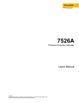
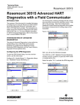
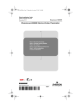
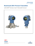
Multifunction calibration
using the 7526A Precision
Process Calibrator
The flexibility and precision
measurement capabilities of the
7526A Precision Process Calibrator make it the ideal tool to
handle multifunction calibration
(voltage, current, thermocouple,
RTD and pressure). This application note provides examples of
how to calibrate a Rosemount
3144 Temperature Transmitter
and Rosemount 3051 Pressure
Transmitter. These two transmitters are widely used in the
process control industry and
provide an excellent starting
point to become familiar with
the 7526A features and interface
(Figure 1). Please take time to
review the 7526A user’s manual
and device specifications before
beginning.
Calibrating a Rosemount
3144 Temperature
Transmitter
Figure 1. Fluke Calibration 7526A interface.
3. Connect a Type J mini connector into the TC input/
output jack as shown in
Figure 2. Make sure to use a
Type J thermocouple (typically black).
4. Connect the bare ends of the
thermocouple wire to terminals 2 (+) and 3 (-) of the
transmitter and run power as
shown in Figure 2, ensuring
that the polarity of the circuit
is connected correctly.
5. Select the TC/RTD button and
toggle to TC.
7526A to the transmitter. This
process adjusts both the slope
and offset of the original factory
curve fit. To perform the sensor
trim, an external HART communicator is needed to execute
the digital commands. In addition, the 4-20 mA output on the
isolated measurement channel is
monitored and used to determine if a D/A trim is required.
Follow these steps:
1. Power on the 7526A and
allow it to warm up.
2. Disconnect any test leads on
the device under test.
7526A
PRECISION PROCESS CALIBRATOR
mA
VOLTS
RTD/
100 mA MAX
OUTPUT
HI
HI
LO
LO
OUTPUT
100V MAX
100V PK
MAX
TC
INPUT/OUTPUT
VOLTS
mA
LOOP
PWR
Press and Hold
for Switch Test
Switch Test
Reset
HART
4 W RTD/
HI
INPUT
HI
CURRENT
20V PK
MAX
SENSE
INPUT
20V PK
MAX
LO
LO
100 V PK
MAX
1
2
3
4
-
+ +
+ + + +
The transmitters covered in
this application note are HART
smart two-wire devices that
require loop power. The 7526A
features a fully isolated measurement channel which can be
used to power the 24 V dc loop,
monitor current, and provide the
250 Ω HART resistor; enabling
direct connection to a HART
communicator.
This example calibrates a
Rosemount 3144 Temperature
Transmitter that is set up to
measure a single Type J thermocouple. To calibrate the
Rosemount 3144, an A/D trim or
two-point sensor trim is performed. A sensor trim allows for
alteration of the transmitter’s
input to a known NIST traceable
source. In this case, the temperature is simulated from the
Application Note
+
Figure 2. Thermocouple and temperature transmitter connection.
From the Fluke Calibration Digital Library @ www.flukecal.com/library
754
DOCUMENTING PROCESS CALIBRATOR
Documenting
Process
Calibrator
6. Once in TC mode, cycle
though the thermocouple
types to Type J by using the
Type/Units key.
7. Select Shift and Output (#7)
to source temperature. Key
in 0.0 °C and press Enter.
8. Select the mA, loop power,
and the HART option on
the isolated side. The mA
reading will be displayed
if all selections are made
correctly.
9. Connect a HART communicator or equivalent across
the 24 V dc power connections. Power on the device
and verify communication.
Save the transmitter configuration and perform an “As
Found” measurement before
making any changes to the
transmitter. This documents
the current state of the
transmitter.
10. Navigate to the Rosemount
Sensor calibration, lower
and upper trim methods.
A complete Menu Tree for
the Rosemount 3144 can be
found in the product reference manual.
11. Verify that the temperature unit of measure on the
7526A matches that of the
HART communicator.
12. Apply the Lower Trim point
or Offset by entering the
value requested by the
HART communicator. This is
typically a negative value.
Follow screen prompts and
proceed to the Upper Trim
point or Slope.
13. Apply the Upper Trim
point and follow screen
prompts to complete the A/D
calibration.
14. Verify the 4-20 mA output
meets published transmitter
specifications by performing
a D/A trim. Since the connections are already made,
simply follow the prompts
from the communicator and
verify the analog output on
the 7526A.
Get it done faster–quick tip
Save time when testing several transmitters that have the same
range by using the available nine preset output setpoints. They may
be recalled on an individual basis, or as an automatic up and down
cycle with configurable dwell time between each setpoint.
Automatic setpoint cycle setup:
1. Select the output mode desired. Example: TC OUT
2. Press the Shift Key and Autoset (#3 Key) to select the AUTOSET
function.
3. At the selection prompt for the sequence ending setpoint number
(AUTO SET POINT#), press the numeric key, 1-9, corresponding to
the final setpoint number of the sequence.
4. At the prompt “DWELL TIME”, “5-500?”, enter the number of
seconds (5 to 500) for the dwell time at each setpoint value, followed by the Enter key.
5. Press any other key to terminate the cycle.
Adding a Fluke 700
Series Pressure Module
To calibrate a pressure transmitter, the pressure measurement
capability needs to first be
configured for the 7526A. Follow
these steps:
1. Connect the Fluke 700 Series
Pressure Module as shown in
Figure 3.
2. Press the
pressure
key. The 7526A will sense
the pressure module
automatically.
Figure 3. Pressure module connection.
2 Fluke Calibration Multifunction calibration using the 7526A Precision Process Calibrator
3. Press the Type/Units key to
select desired units.
It is important to review the
recommended calibration procedure and tolerances required
by the manufacturer to ensure
the proper pressure module is
selected. The pressure transmitter used in this application note
is a simple gage unit that is referenced to atmospheric pressure.
Calibrating a Rosemount 3051 Pressure
Transmitter
Follow these steps to calibrate the Rosemount pressure
transmitter:
1. Make the necessary connections to the pressure module,
pressure source, and pressure transmitter as shown
in Figure 4. Connections
must be leak free for proper
calibration. Connect to the
High Side (H) and make sure
the Low Side (L) is vented to
atmosphere.
2. Connect the test leads from
the transmitter to the HI (+)
and LO (-) terminals, ensuring that the polarity of the
circuit is connected properly
as illustrated.
3. Select loop power and the
HART option on the isolated
side. The mA reading will be
displayed if all connections
are made correctly.
4. Vent the pressure source to
atmosphere and press the
Shift key and Zero (#9 key) to
establish a good zero. Close
the valve on the pressure
source to begin calibration.
The 7526A should be reading
close to 4.0000 mA.
5. Connect the HART communicator or equivalent across
the 24 V dc power connections. Power on the device
and verify communication.
Save the transmitter configuration and perform an
“As Found” measurement
before making any changes to
the transmitter. This documents the current state of the
transmitter.
6. Navigate to the Rosemount
sensor calibration, lower
and upper trim methods. A
complete menu tree for the
Rosemount 3051 can be
found in the product reference manual.
7. Verify that the pressure units
of measure on the 7526A
match those of the HART
communicator.
8. Apply the Lower Trim point
requested by the HART communicator by adjusting the
pressure source. This is typically zero for pressure. Follow
screen prompts and proceed
to the Upper Trim point.
9. Apply the Upper Trim point
and follow screen points to
complete the A/D calibration.
10. Verify the 4-20 mA output
meets published transmitter
specifications by performing
a D/A trim. Since the connections are already made,
simply follow prompts from
the communicator and verify
the analog output on the
7526A.
Figure 4. Pressure module, source, and transmitter connection.
Summary
The 7526A Precision Process Calibrator is a
versatile benchtop instrument for multifunction calibration. This application note has
illustrated how the 7526A is used to calibrate two transmitters that are popular in the
process control industry—the Rosemount 3144
Temperature Transmitter and Rosemount 3051
Pressure Transmitter. Since the 7526A can
simultaneously source and measure voltage,
current or resistance, it can calibrate a range
of other process tools beyond temperature and
pressure transmitters. These tools include RTD
and thermocouple readouts, pressure gauges,
digital process simulators, data loggers, multimeters, and more.
Fluke Calibration. Precision, performance, confidence.™
Fluke Calibration
PO Box 9090,
Everett, WA 98206 U.S.A.
Fluke Europe B.V.
PO Box 1186, 5602 BD
Eindhoven, The Netherlands
For more information call:
In the U.S.A. (877) 355-3225 or Fax (425) 446-5116
In Europe/M-East/Africa +31 (0) 40 2675 200 or Fax +31 (0) 40 2675 222
In Canada (800)-36-FLUKE or Fax (905) 890-6866
From other countries +1 (425) 446-5500 or Fax +1 (425) 446-5116
Web access: http://www.flukecal.com
©2006-2012 Fluke Calibration. Specifications subject to change without notice.
Printed in U.S.A. 11/2012 4264601A_EN Pub-ID: 12003-eng
Thermocouple transmitter calibration
Modification of this document is not permitted without written permission
from Fluke Calibration.
3 Fluke Calibration Multifunction calibration using the 7526A Precision Process Calibrator