1
W406 WinCE
User’s Manual
Third Edition, December 2009
www.moxa.com/product
© 2009 Moxa Inc. All rights reserved.
Reproduction without permission is prohibited.
W406 WinCE User’s Manual
The software described in this manual is furnished under a license agreement and may be used only in
accordance with the terms of that agreement.
Copyright Notice
Copyright © 2009 Moxa Inc.
All rights reserved.
Reproduction without permission is prohibited.
Trademarks
MOXA is a registered trademark of Moxa Inc.
All other trademarks or registered marks in this manual belong to their respective manufacturers.
Disclaimer
Information in this document is subject to change without notice and does not represent a commitment on the
part of Moxa.
Moxa provides this document “as is,” without warranty of any kind, either expressed or implied, including, but
not limited to, its particular purpose. Moxa reserves the right to make improvements and/or changes to this
manual, or to the products and/or the programs described in this manual, at any time.
Information provided in this manual is intended to be accurate and reliable. However, Moxa assumes no
responsibility for its use, or for any infringements on the rights of third parties that may result from its use.
This product might include unintentional technical or typographical errors. Changes are made periodically to the
information in this manual to correct such errors, and these changes are incorporated into new editions of the
publication.
Technical Support Contact Information
www.moxa.com/support
Moxa Americas:
Toll-free: 1-888-669-2872
Tel: +1-714-528-6777
Fax: +1-714-528-6778
Moxa China (Shanghai office):
Toll-free: 800-820-5036
Tel: +86-21-5258-9955
Fax: +86-10-6872-3958
Moxa Europe:
Tel: +49-89-3 70 03 99-0
Fax: +49-89-3 70 03 99-99
Moxa Asia-Pacific:
Tel: +886-2-8919-1230
Fax: +886-2-8919-1231
Table of Contents
Chapter 1
Introduction ..................................................................................................1-1
Overview.................................................................................................................................. 1-2
W406 Software ........................................................................................................................ 1-2
Application Development Environment ....................................................................... 1-2
Networking and Communications Capabilities ............................................................ 1-3
Supported Servers and Daemons .................................................................................. 1-3
Obtaining the Firmware Build Version .................................................................................... 1-4
Memory and File Systems ....................................................................................................... 1-4
RAM File System ......................................................................................................... 1-4
Flash File System.......................................................................................................... 1-4
External File System..................................................................................................... 1-4
Cautions when Using File Systems .............................................................................. 1-4
Using a RAM File System instead of a Flash File System ........................................... 1-5
Hive-based Registry................................................................................................................. 1-5
Connect to Network via Ethernet............................................................................................. 1-5
Cellular Networking ................................................................................................................ 1-5
Inserting an SD Card into the Computer.................................................................................. 1-6
Connecting a USB Mass Storage Device to the Computer ...................................................... 1-6
Serial Ports............................................................................................................................... 1-6
Console Port ................................................................................................................. 1-6
RS-232/422/485 Serial Ports ........................................................................................ 1-7
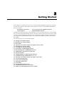
Chapter 2
Getting Started .............................................................................................2-1
Starting Your W406 Computer................................................................................................. 2-2
Resetting Your W406 Computer .............................................................................................. 2-2
Boot Loader ............................................................................................................................. 2-3
Operating Your W406 Computer through the Serial Console.................................................. 2-3
Changing the Network Settings ............................................................................................... 2-4
Accessing Files with File Sharing............................................................................................ 2-4
Connecting to a GPRS/EDGE Network................................................................................... 2-5
Disconnecting from a GPRS/EDGE Network ......................................................................... 2-7
GPRS/EDGE Connection Error Detection............................................................................... 2-7
SIM Card Utilities.................................................................................................................... 2-8
Sending, Reading, and Deleting SMS Messages ..................................................................... 2-9
Troubleshooting the GPRS/EDGE Connection ..................................................................... 2-10
Operating Your W406 Computer through a Telnet Client...................................................... 2-12
User/Group Management....................................................................................................... 2-12
System Time Management..................................................................................................... 2-13
Adjusting OS Time Zone ....................................................................................................... 2-13
SNTP Client ........................................................................................................................... 2-13
Starting and Stopping Services .............................................................................................. 2-14
Troubleshooting Network Connectivity................................................................................. 2-14
Simple Network Management Protocol (SNMP)................................................................... 2-15
Chapter 3
Web-based Management System ...............................................................3-1
Logging into the Web-based Management System .................................................................. 3-2
System Information.................................................................................................................. 3-2
Networking/Server Configuration............................................................................................ 3-3
Serial Port Configuration ......................................................................................................... 3-3
Process (Thread) Monitoring/Control...................................................................................... 3-4
Launching Processes Automatically ........................................................................................ 3-4
Monitoring and Controlling Services....................................................................................... 3-5
Binary/Text File Management ................................................................................................. 3-6
Appendix A Firmware Upgrade Procedure.................................................................... A-1
A. Configure HyperTerminal for the Console Port...................................................... A-2
B. Download and Install the TFTP program................................................................ A-7
C. Download and Upgrade the Firmware through HyperTerminal. ............................ A-8
Appendix B Application Development ........................................................................... B-1
Developing an application with VS2005 .................................................................................B-1
Visual C++ Library ..................................................................................................................B-2
Visual C++ Examples.................................................................................................B-11
Net Compact Framework Library...............................................................................B-11
Visual C# Examples ...................................................................................................B-21
1
Chapter 1
Introduction
The W406 embedded computer has two RS-232/422/485 serial ports, one 10/100 Mbps Ethernet
port, an embedded GSM/GPRS/EDGE module, an SD socket interface for storage expansion, one
USB 2.0 host port, four digital input channels, and four digital output channels. This combination
of features makes the W406 ideal for your wireless embedded applications.
RISC-based W406 embedded computers come with the Windows® CE operating system
pre-installed. Microsoft® Windows® CE 6.0 is an open, scalable, 32-bit operating system that
allows users to build a wide range of innovative, small footprint devices. A typical Windows®
CE-based device is designed for a specific use, and often runs disconnected from other computers,
or distributed as a front-end to a centralized host. Examples include enterprise tools, such as
industrial controllers, communications hubs, point-of-sale terminals, and display devices, such as
HMI, advertisement appliances, and interactive panels.
The following topics are covered in this chapter:
Overview
W406 Software
¾ Application Development Environment
¾ Networking and Communications Capabilities
¾ Supported Servers and Daemons
Obtaining the Firmware Build Version
Memory and File Systems
¾ RAM File System
¾ Flash File System
¾ External File System
¾ Cautions when Using File Systems
¾ Using a RAM File System instead of a Flash File System
Hive-based Registry
Connect to Network via Ethernet
Cellular Networking
Inserting an SD Card into the Computer
Connecting a USB Mass Storage Device to the Computer
Serial Ports
¾ Console Port
¾ RS-232/422/485 Serial Ports
W406-CE User’s Manual
Introduction
Overview
The W406 is an embedded Linux or WinCE computer that features 2 software selectable
RS-232/422/485 ports, 1 Ethernet port, and quad-band GSM/GPRS/EDGE 900/1800/850/1900
MHz for cellular communication. It also comes with an SD socket, USB host, and 4 digital input
and 4 digital output channels, making it the ideal computer for a variety of industrial applications
such as data acquisition, data processing, protocol conversion, and remote device control and
monitoring via wireless communication. The W406 comes pre-installed with either Linux or
WinCE 6.0, and offers a reliable and powerful computing platform for industrial environments.
Programmers will find that the W406 provides a convenient programming environment for
producing bug-free industrial applications at a lower cost.
W406 Software
The W406 embedded computer is a ready-to-run, RISC-based, “headless” computer with a robust
and network-centric design. It uses the Microsoft® Windows® CE 6.0 operating system.
Developers of embedded communication applications will find that the open programming
environment makes the W406 well-suited for both new system development and legacy system
migration.
Application Development Environment
y
C Libraries and Run-times—Compared to the C libraries and run-times used on a desktop
PC running Windows®, the C libraries and run-times on a W406 WinCE are a subset of the
WIN32 APIs. The system supports a full ANSI C run-time, standard input/output library,
standard input/output ASCII library, and standard ASCII string functions. In addition, C++
compiler exception handling and Run-Time Type Information (RTTI) equivalent to desktop
C++ compilers are supported.
y
Active Template Library—Active Template Library (ATL) for Windows CE is a C++
template library designed to help create small, fast Microsoft® ActiveX® servers. An ActiveX
server is a dynamic-link library (DLL) or executable (.exe) that contains one or more
Component Object Model (COM) components. COM components can be anything from a
simple dialog box to a full ActiveX control.
y
Component Services (COM)—The Common Object Model (COM) is an operating
system-independent, object-oriented system for creating binary software components that can
interact with other COM-based components in the same process space, in other processes, or
on remote machines.
y
Microsoft® .NET Compact Framework 2.0 with service pack 2—Offers a choice of
languages, initially Microsoft® Visual Basic® and Microsoft® Visual C#, and eliminates the
common problems of language interoperability.
y
XML—support for XML Query Language (XQL)
y
Winsock 2.2—Provides enhanced capabilities over Winsock 1.1, including installable service
providers for additional third-party protocols, and Media sense.
1-2
W406-CE User’s Manual
Introduction
Networking and Communications Capabilities
y
y
y
y
y
Simple Network Management Protocol (SNMP)—Monitors remote connections to the
network.
Simple Network Time Protocol (SNTP) Client—Provides support for synchronizing the
device’s system time with an SNTP server, and supports Daylight Savings Time.
Serial Communications—In addition to the 16550 UART driver bound to a debug port and
the console port, a special driver for 2 additional Moxa serial ports is also included.
Network Utilities (IpConfig, Ping, Route)—Utilities for troubleshooting various network
problems.
TCP/IP—Includes IP, Address Resolution Protocol (ARP), Internet Control Message Protocol
(ICMP), Internet Group Membership Protocol (IGMP), Transmission Control Protocol (TCP),
User Datagram Protocol (UDP), name resolution and registration, and DHCP.
Supported Servers and Daemons
y
Telnet Server—A sample server that allows remote administration through a standard Telnet
client.
y
FTP Server—A sample server used for transferring files to and from remote computer
systems over a network using TCP/IP.
y
File Server—The File Server functionality in Microsoft® Windows® CE enables clients to
access files and other resources over the network.
y
Dial-up Networking—Consists of RAS client API and the Point to Point Protocol (PPP).
RAS and PPP support Extensible Authentication Protocol (EAP) and RAS scripting.
y
Watchdog—A CPU Hardware function for reset CPU in a user specified time interval. You
must call the MOXA library function to trigger it.
y
Web Server (HTTPD)—Includes ASP, ISAPI Secure Socket Layer support, SSL 2, SSL 3,
Transport Layer Security (TLS/SSL 3.1) public key-based protocols, and Web Administration
ISAPI Extensions.
1-3
W406-CE User’s Manual
Introduction
Obtaining the Firmware Build Version
There are two ways to obtain the firmware version of W406 embedded computers. This
information is particularly important for identifying the features supported by the computer.
y
Examine the welcome message after you log on to the computer.
y
Log on to the web-based management system (described in a later chapter) to view the system
information.
Memory and File Systems
The 32 MB of SDRAM is divided into two main parts. The main memory, which houses the
operating system and user applications, has a capacity of about 20 MB. The kernel image occupies
the remainder of the memory space.
RAM File System
The internal file system in the W406 computer controls access to flash and also provides file
storage in the object store, which is in the RAM. The root directory is a RAM file system of size 4
MB. Child directories such as “Windows,” “Temp,” “My Documents,” “Network,” and “Program
Files” are under the root directory. They can be used for storing temporary files for your
applications. However, do not place persistent files or applications in these directories because
they will be deleted when the system is shut down. Instead, place them in the “NORFlash”
directory.
Flash File System
The Flash file system provides persistent storage for applications and related data, even when the
main power supply is lost. The system integrates the read-only files that are stored on the Flash
with the read/write files from both applications and users. A child directory named “NORFlash” is
created under the root; the size of the directory is 3 MB.
External File System
The additional file systems from USB and SD storage devices are placed in the root of the internal
file system. If you intend to use these devices to port data between your PC and the W406
computer, you should format them using the FAT file system on your PC.
Cautions when Using File Systems
We recommend storing your programs only in the on-board NOR Flash. Please store the log data
generated by your programs in an external storage device such as an SD card or Network File
System. Note that a Network File System will generally provide more storage space than the SD
card. In addition, it is easier to replace a full or damaged Compact Flash than an on-board NOR
Flash.
A NOR Flash has a life cycle of 100,000 write operations in block (128 KB) level, and does not
support BBM (Bad Block Management). For this reason, the FAT file system would not know
when a flash block has reached its cycle, and would try to scan the block repeatedly.
FAT sequentially searches for free memory space for write operations. After deleting many files,
the memory space could become fragmented, making it more difficult to search for free space. If
your program updates (deletes and then creates) a file frequently, it is quite possible that the
program writes data to the same flash area. In the long run, FAT would be blocked when scanning
the area and would cause the operating system to hang.
1-4
W406-CE User’s Manual
Introduction
An SD card has its own life cycle. Since most SD cards are made from a NAND Flash, their
hardware controllers implement BBM. This feature allows FAT to skip bad blocks if they exist.
Furthermore, the memory space of an SD card is much larger than that of the NOR Flash. Using
this space cautiously will ensure that its life cycle is not exceeded. When creating a file for storing
log data, we suggest creating a large empty file (e.g., 30 MB), and then writing data evenly to that
space. When the space is used up, the program rewinds the write operations. As a result, the
number of write operations to each block is reduced.
Using a RAM File System instead of a Flash File System
Even though data in the RAM file system will be deleted after shutting off the power, using the
RAM file system has several advantages over using the Flash file system, including faster
read/write access and not needing to deal with the life cycle issue.
For important applications that relay data back to the host directly, you should write the necessary
log data to the RAM file system. After the host accesses the data, the application erase the data,
freeing up the memory space for further use.
The embedded computer has limited resources, and designers should decide if storing data in a file
system is really necessary. If it is necessary, be sure to choose the most appropriate file system.
Hive-based Registry
The W406 uses a hive-based registry, not a RAM-based registry. A hive-based registry stores
registry data inside files, or hives, which can be kept on any file system. This removes the need to
perform a backup and restore on power off.
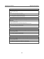
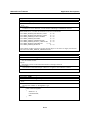
Under default settings, registry data will be auto flushed. If AutoFlush is disabled, the
RegFlushKey function is needed to change the registry value in your applications. The
AutoFlush.exe utility is provided to change the auto-flush setting.
Type autoflush -d to disable the auto-flush setting.
\>autoflush -d
Or type autoflush -e to enable the auto-flush setting.
\> autoflush -e
Or just type autoflush to display the current status.
Connect to Network via Ethernet
The W406 computer offers a 10/100M RJ-45 Ethernet port for network redundancy.
Cellular Networking
The W406 computer has been embedded with a GSM/GPRS/EDGE cellular module for a reliable
and stable wireless communication. It supports quad-band GSM/GPRS/EDGE 850/900/1800/1900
MHz, and GPRS/EDGE Class 10. Meanwhile, it offers SMS tunnel mode for auto configuration
and SIM card authentication.
1-5
W406-CE User’s Manual
Introduction
Inserting an SD Card into the Computer
The W406 is equipped with an SD slot. When an empty SD card is inserted into the slot, the
computer automatically formats it in the FAT file system. This process takes a few minutes to
complete. After an SD card is inserted, the embedded computer will create a directory named
“StorageDisk” under the root directory. The “StorageDisk” directory controls access to the SD
storage space. The embedded computer will create a directory called “StorageDisk2” if another
USB storage device is plugged in at a later time.
Connecting a USB Mass Storage Device to the Computer
The USB mass storage device is highly portable between your PC and a computer that does not
support the TFAT system. We suggest that you format your devices with the FAT format. When
the first USB storage device is plugged into the slot on the back of the computer, a directory
named “USBDisk” under the root directory is created in the internal file system as a link to the
storage device. The embedded computer will create a directory called “StorageDisk2” if another
SD storage device is plugged in at a later time.
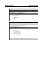
The following table lists USB mass storage devices that have been tested successfully for
compatibility.
Vendor
CRUZER
Intel
Abocom
PQI
Transcend
Transcend
Device Name
mini
Flash memory
Size
128 MB
128 MB
128 MB
256 MB
512 MB
1 GB
JetFlash
JetFlash
ATTENTION
Some USB storage devices may not be detected by the system. We suggest that you use one of
the devices listed in the above table, since these USB mass storage devices have been tested
successfully for compatibility.
Serial Ports
Console Port
The serial console port, located on the bottom panel is a 4-pin pin-header RS-232 port. It is
designed for serial console terminals, which are useful for viewing boot-up messages, system
configuration and develop applications.
1-6
W406-CE User’s Manual
Introduction
RS-232/422/485 Serial Ports
The W406-CE embedded computer contains two software-selectable RS-232/422/48 serial ports
for reliable and stable serial communication. They both support non-standard baudrate settings of
up to 921,600 bps.
To configure the interface of the serial ports, simply use the setinterface command in telnet or
console mode. Please note that Port 1 refers to COM1, while Port 2 refers to COM2.
You may use the setinterface –h command to learn the configuration syntax. For example, to
configure Port 1 as RS-422, enter SetInterface COM1: 2.
1-7
2
Chapter 2
Getting Started
In this chapter, we explain how to use a PC to operate a W406 embedded computer. We will refer
to the PC that connects to the W406 as the development workstation, and the W406 embedded as
the target computer.
development workstation =
target computer
=
PC used to operate the embedded computer
W406 embedded computer
In addition, we describe the steps you should follow to carry out certain operations, such as setting
the system time and troubleshooting network connectivity. Some of these operations can be carried
out using system commands after gaining access to the target computer, and others can be carried
out using a web-based management system. The web-based management system is described in a
later chapter.
The following topics are covered in this chapter:
Starting Your W406 Computer
Resetting Your W406 Computer
Boot Loader
Operating Your W406 Computer through the Serial Console
Changing the Network Settings
Accessing Files with File Sharing
Connecting to a GPRS/EDGE Network
Disconnecting from a GPRS/EDGE Network
GPRS/EDGE Connection Error Detection
SIM Card Utilities
Sending, Reading, and Deleting SMS Messages
Troubleshooting the GPRS/EDGE Connection
Operating Your W406 Computer through a Telnet Client
User/Group Management
System Time Management
Adjusting OS Time Zone
SNTP Client
Starting and Stopping Services
Troubleshooting Network Connectivity
Simple Network Management Protocol (SNMP)
W406-CE User’s Manual
Getting Started
Starting Your W406 Computer
Connect the SG wire to the shielded contact located in the upper left corner of the W406 computer,
and then power it up by connecting it to the power adaptor. It takes about 30 to 60 seconds for the
system to boot up. Once the system is ready, the “Ready” LED will light up. The light will stay lit
until you shut down the computer.
Resetting Your W406 Computer
When the target computer stops responding, or an application locks up, or the target computer fails
to work normally, you may need to restart or reset the target computer’s operating system. We
provide four ways to restart or reset the operating system.
Warm-Start: When the computer is powered on, insert a pin into the “Reset” hole next to the
serial console, and hold for 1 to 2 seconds. The computer will reboot automatically.
Cold-Start: Unplug the power line and then plug it back in again. The computer will reboot
automatically.
Resetting to Factory Defaults: If the computer is not working properly, and you want to reset it
back to factory default settings, press and hold the “Reset” button for at least 5 seconds. The
buzzer will sound while the factory default settings are being loaded. After the factory defaults
have been loaded, the computer will reboot automatically.
Resetting the System: In rare circumstances, the FAT file system may be damaged by executing
improper applications, or due to an unstable power supply. In this case, the computer may fail to
boot up if the FAT table crashes. In order to get the system back up and running, you will need to
format the flash disk and reset the operating system. Note that all user files and configurations will
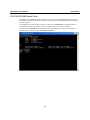
be erased. The following steps show how to format the flash disk through boot loader utilities.
Step 1: Power off the W406 embedded computer.
Step 2: Connect the W406 to your PC using the console port cable.
Step 3: Start a terminal program with the settings: Baudrate = 115200, no hardware flow control,
8 N 1, character set VT100.
Step 4: Hold in the “DEL” key on your PC.
Step 5: Power on the W406. You will be guided to boot loader utility menu.
2-2
W406-CE User’s Manual
Getting Started
Step 6: Type “2” for “Format User Disk”, and then press Enter.
Step 7: After a few seconds, you will see the bootloader menu again. Unplug the power line and
then plug it back again. It takes about 3 minutes to reset the operating system.
Boot Loader
For addressing OS stability issues, we provide an easy and useful function with Boot Loader for
the following tasks:
1. Reset to default: you can set the flag to reset WinCE 6.0 to factory default settings.
2. Format storage flash: The CE 6.0 file system is an FAT that can be damaged by unstable
power or improper application execution. If the FAT table crashes, do not start up the OS. You
can, however, format the file system and reboot your W406.
At startup, the W406 will check the file system and re-partition it if the file system is empty.
3. Firmware upgrade: If you find a new firmware from Moxa’s website, you can upgrade the
firmware with this function (details in appendix A).
Go to the boot loader menu from serial console:
Step 1: Power off your W406 device.
Step 2: Make sure the serial console wire is connected to your PC correctly.
Step 3: Go to [Start] Æ [Programs] Æ [Accessories] Æ [Communication] Æ [Terminal] to
create a new terminal communication with the following settings: baudrate of 115200,
no hardware flow control, 8 N 1, and character set VT100.
Step 4: Activate this terminal window on your PC.
Step 5: Hold “DEL” key continuously.
Step 6: Power on the W406 device.
Operating Your W406 Computer through the Serial Console
The serial console port (located on the bottom panel) gives users a convenient way of connecting
the development workstation to the console utility of the target computer. This method is
particularly useful when using the computer for the first time.
After you have wired a serial cable, go back to the development workstation and start a terminal
program (e.g., HyperTerminal) by using the settings shown below for the serial console port.
Baudrate
Parity
Data bits
Stop bits
Flow Control
Terminal
115200 bps
None
8
1
None
ANSI
After a successful connection, type the login name and password as requested to log on to the
computer. The default values are both admin.
Login: admin
Password: admin
2-3
W406-CE User’s Manual
Getting Started
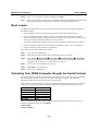
Changing the Network Settings
The W406 computer has one network interface. There is no default IP address; the default network
setting is configured as DHCP. If you have a DHCP server, simply connect the W406 to your
network using an Ethernet cable. An IP address will automatically be appointed to the W406. If
you would like to use a fixed IP address, you should use netconfig command.
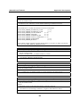
The netconfig command is a utility that is used to complete the task. Before changing the IP
addresses, type netconfig -h to list the help for this command.
\> netconfig -h
Usage: netconfig -n <AdapterName | Alias> [-EnableDHCP] [-i <IP address>] [-m < etmask>]
[-g <gateway>] [-d <DNS server>] [-w <WINS Server>] [-noask] e.g.: netconfig -n
IXP425ETHNPE1 -i 192.168.10.101 -g 192.168.10.254: netconfig -n CS89501 -i
192.168.12.101 -m 255.255.0.0
Alias: LAN1=CS89501
For example, if your development workstation has a LAN port at 192.168.1.1, and the IP address
of the Domain Name Server (DNS) is 192.168.2.6, execute the following command.
\> netconfig –n LAN1 –i 192.168.1.5 –m 255.255.255.0 –g 192.168.1.254 –d 192.168.2.6
Use the netconfig command to view the updated settings.
\> netconfig
LAN1 Interface Configuration:
IP Address:
192.168.1.5
SubNet Mask:
255.255.255.0
Gateway:
192.168.1.254
DNS:
192.168.2.6
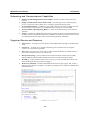
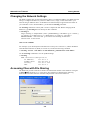
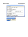
Accessing Files with File Sharing
The W406-CE provides a File Server feature for efficient file transfer to the W406-CE. Navigate
to Start Æ Run and input \\x.x.x.x (the device IP), and then you should see the following
authentication window. Enter the username and password to access the W406-CE.
2-4
W406-CE User’s Manual
Getting Started
After logging in, enter the netshare -h command to learn how to configure shared folders.
For example, netshare -s docs “\My Documents” -a admin will share the “My Documents”
folder as “docs” for the user “admin”.
Connecting to a GPRS/EDGE Network
Before connecting to a GPRS/EDGE network, make sure the SIM card is properly installed and
the antenna is connected. (Please refer to W406 Hardware User’s Manual for installation details.)
Please note the SIM card must be installed when the embedded computer is powered off. The LED
indicators on the top panel can be used to check the signal strength. (A background process
“gprssignalled.exe” is responsible for this task.)
NOTE: Make sure that Mobile Equipment Error Message Format (CMEE) has not been set,
or the GPRS connection functions may return incorrect values.
1. To create a connection, use the following command:
/> gprs_connect
You can connect to the GPRS/EDGE network using gprs_connect.exe. For more details, please see
the command syntax gprs_connect –h.
2-5
W406-CE User’s Manual
Getting Started
When the GPRS/EDGE has successfully connected, you can use gprs_connection_status.exe to
check the GPRS/EDGE connection status or use ipconfig.exe to verify the Network Status.
2. To create a permanent GPRS/EDGE connection:
If the connection fails, use the gprs_reconnect.exe command to re-connect to the GPRS network
again. For more details, please see the command syntax gprs_reconnect –h.
Use gprs_disconnect –r to stop the gprs_reconnect.exe daemon.
3. To re-create an entry for connection, use the following command.
If you would like to change your SIM card or to use another APN name, you must execute the
“gprs_connect –d” command to re-detect the new parameters for the current RAS entry.
2-6
W406-CE User’s Manual
Getting Started
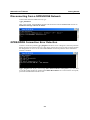
Disconnecting from a GPRS/EDGE Network
To disconnect from the GPRS network, type
/>gprs_disconnect
After a few seconds, the embedded computer will disconnect from the GPRS/EDGE network. A
notification message will NOT be shown.
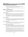
GPRS/EDGE Connection Error Detection
To detect connection problems, gprs_diagnose.exe allows users to diagnose connection problems
during the network connection process. This utility will execute a series of steps to check whether
the configuration is correct or not. Most GPRS/EDGE connection problems can be indentified
with this command.
If gprs_diagnose.exe displays the message The Cellular modem is unresponsive, you will need
to reset the cellular modem by pushing the Cellular Reset Button. It is located on the front panel,
just beside the SD/SIM card socket cover.
2-7
W406-CE User’s Manual
Getting Started
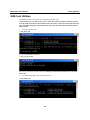
SIM Card Utilities
The W406 provides some utilities for manipulating the PIN code.
NOTE: Make sure your PIN code is correct. After three failed attempts at entering the PIN
code, the SIM card will be locked and the PUK code will be required to unlock the SIM card.
After ten failed attempts at entering the PUK code, the SIM card will be invalidated and no
longer usable.
1. To input your PIN code:
/> sim_input_pin
2. To verify the SIM card status.
/> sim_get_pin_status
There are 4 possibilities for SIM card status: Ready, No SIM card, Need PIN code, and Need
PUK code.
3. To enable or disable the PIN code authentication.
/>sim_enable_pin
2-8
W406-CE User’s Manual
Getting Started
4. To change the PIN code of the SIM card.
/> sim_change_pin
5. To unlock the SIM card, if your SIM card status is Need PUK code.
/> sim_unlock
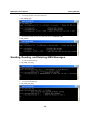
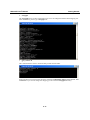
Sending, Reading, and Deleting SMS Messages
1. To send an SMS message
/> sms_send_text_msg
2. To read an SMS Message
/> sms_read_text_msg
2-9
W406-CE User’s Manual
Getting Started
3. To delete an SMS message
/>sms_remove_msg
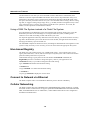
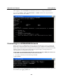
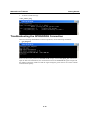
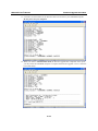
Troubleshooting the GPRS/EDGE Connection
When encountering GPRS/EDGE connection problems, use the following commands:
1. gprs_diagnose
In the case above, the problem is Need PIN Code. Simply use the sim_input_pin command to
input the PIN code. Meanwhile, this command also shows the GPRS/EDGE signal strength and
the module temperature. Make sure that the signal strength is greater than 10 for a better cellular
communication quality.
2-10
W406-CE User’s Manual
Getting Started
2. setregapn
The setregapn.exe is an APN configuration tool. You can change the ISP and APN mapping. For
more information, please type “setregapn –h”.
3. gprs_connect -d
This command allows users to check the ISP provider and the APN.
In the case above, users may know the name of the ISP is Chunghwa Teleco and the default APN
is Internet. If you want to change the mapping you must use the setregapn.exe utility.
2-11
W406-CE User’s Manual
Getting Started
Operating Your W406 Computer through a Telnet Client
Use a cross-over Ethernet cable to connect directly from your development workstation to the
W406 computer, or use a straight-through Ethernet cable to connect the computer to a LAN hub or
switch. Next, use the Telnet client in your development workstation to connect to the Telnet
console utility of the W406 computer. After connecting successfully, type the login name and
password as requested to log on to the computer.
Login: admin
Password: admin
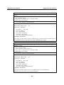
After logging on through the console port or through a Telnet client, a list of commands are
available to operate the computer. Use “HELP” to display all of the commands and type “HELP
[command name]” to display extended help for the given command. Some of these commands,
such as “DATE” and “TIME” are very useful for managing the computer’s system time. Other
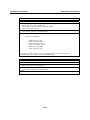
commands, such as “DIR” and “MKDIR” are good utilities for file management. For example, to
inspect the file structure of the root directory, type DIR.
> dir /b
Network
NORFlash
My Documents Program Files Temp
Windows
User/Group Management
User Group: You should assign specific services, such as ftp and Telnet, to defined user groups
so that these services are accessible only by the users within the permissible user group. Three user
groups, namely ftpd, telnetd, and httpd, are already created by default for your convenience.
Adding a Group: Use the command useradd –g <groupName> to create a user group.
\> useradd –g yyyy
group yyyy has been added.
Deleting a Group: To remove a group, use the command userdel –g <groupName>.
\> userdel –g yyyy
group yyyy has been removed.
Adding a User: Use the command useradd <newUserID> to add a user to the system. The user’s
password, by default, is the same as the user name.
\> useradd xxxx
user xxxx has been added.
In addition, you can permit this user to access a particular service by typing -g followed by the
user group name of the service, i.e., useradd –g <groupName> <newUserID>. For example,
\> useradd –g telnetd xxxx
user xxxx is existent
group telnetd is existent
2-12
W406-CE User’s Manual
Getting Started
user xxxx has been added to group yyyy
Deleting a User: Use the command userdel <userID> to delete a user from the system. User
“admin” CANNOT be deleted.
\> userdel xxxx
user xxxx has been deleted
You can also just remove a user from a user group by using the command userdel –g
<groupName> <newUserID>. For example,
\> userdel –g yyyy xxxx
user xxxx has been removed from group yyyy
System Time Management
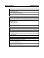
Setting the System Time Manually: Use the date and time commands to query the current
system date/time, or to set a new system date/time.
\> date
The current date is: Tuesday, November 22, 2005
Enter the new date (mm-dd-[yy]yy): 12-23-05
\> date /T
Wednesday, November 23, 2005
\> time
The current time is: 5:27:17 PM
Enter the new time (hh:mm:ss): 16:02:00
\> time /T
4:02:04 PM
Adjusting OS Time Zone
In the web manager, you can adjust your current system Time Zone.
The system time will not be updated automatically after the time zone has been changed; you must
reboot your system for it to take effect.
SNTP Client
In the web manager, you can adjust your SNTP setting.
After the SNTP is enabled, the system time will automatically update so you must reboot your
system for updates to take effect.
2-13
W406-CE User’s Manual
Getting Started
Starting and Stopping Services
After booting up, the W406 computer runs several services continuously to serve requests from
users or other programs. Some important services are telnet (“TEL0:”), console (“CON0:”), world
wide web HTTP (“HTP0:”), and file transfer FTP (“FTP0:”). If you rarely use these services, you
can still start up or stop a service with its associated name by using the services command. For
example:
Start the FTP service with the following command:
\> services start FTP0:
Stop the FTP service with the following command:
\> services stop FTP0:
Troubleshooting Network Connectivity
The ipconfig tool prints the TCP/IP-related configuration data of a host, including the IP addresses,
gateway, and DNS servers.
\> ipconfig /all
Windows IP configuration
Ethernet adapter Local Area Connection:
IP Address: 192.168.30.127
Subnet Mask: 255.255.255.0
Adapter Name: CS89501
Description: CS89501
Adapter Index: 2
Address: 00 90 e8 00 d1 23
DHCP Enabled: NO
Host name: W406
Domain Name: moxa.com
DNS Servers: 192.168.1.99
192.168.1.98
NODETYPE: 8
Routing Enabled: NO
Proxy Enabled: NO
To troubleshoot network connectivity or name resolution, use the ping command. This command
verifies IP-level connectivity to another TCP/IP computer by sending Internet Control Message
Protocol (ICMP) Echo Request messages. The corresponding return Echo Reply messages are
displayed, along with round-trip times. For more information, type ping without parameters.
\> ping www.moxa.com
Pinging Host www.moxa.com [192.168.1.16]
Reply from 192.168.1.16: Echo size=32 time<1ms TTL=126
Reply from 192.168.1.16: Echo size=32 time<1ms TTL=126
Reply from 192.168.1.16: Echo size=32 time<1ms TTL=126
2-14
W406-CE User’s Manual
Getting Started
The route utility allows you to view or modify network routing tables. Type this command
without parameters to view a list of functions.
\> route
To view current routing items in the tables, type
\> route PRINT
To add a routing item on network interface 1, type
\> route ADD 192.168.0.0 MASK 255.255.0.0 192.168.15.254 IF 2
To delete a routing item, type
\> route DELETE 192.168.0.0
Simple Network Management Protocol (SNMP)
SNMP is the standard Internet protocol for network management, and belongs to the TCP/IP
protocol suite. SNMP was developed to monitor and manage networks. It uses a distributed
architecture that consists of agents and managers:
y
The SNMP agent is an SNMP application that monitors network traffic and responds to queries
from SNMP manager applications. The agent also notifies the manager when significant
events occur by sending a trap.
y
An SNMP manager is an SNMP application that generates queries to SNMP-agent applications
and receives traps from SNMP-agent applications.
The W406 computer installs an SNMP agent to serve as an SNMP device. You should install the
SNMP manager on the workstation computer (for example, a Linux system) that monitors the
network. After installing the nodes, you need to configure the SNMP manager and agent.
To check SNMP agent capabilities on a target W406 computer (e.g., network IP at 192.168.3.127),
log on to the workstation computer on which the SNMP manager resides, and type:
\> snmpwalk -v 2c -c public 192.168.3.127 system
SNMPv2-MIB::sysDescr.0 Microsoft Windows CE Version 6.0 (Build 1400)
SNMPv2-MIB::sysObjectID.0 SNMPv2-SMI::enterprises.8691.13.406
SNMPv2-MIB::sysUpTime.0 1282929
SNMPv2-MIB::sysContact.0 Your System Contact Here
SNMPv2-MIB::sysName.0 WindowsCE
You will see a series of messages from the SNMP agent on the W406 computer. You may then
proceed to monitor and manage the computer.
2-15
3
Chapter 3
Web-based Management System
Note: You must use Internet Explorer 5.5 or above to access the web-based management
system.
W406-CE ready-to-run embedded computers are network-centric platforms designed to be used as
front-end computers for data acquisition and industrial control. Due to the distributed
characteristics of the devices that these computers control, they often reside in harsh environments
away from the system administrator. To manage these computers, operations such as
networking/server configuration, file management, and process (thread) monitoring/control are
critical.
The following topics are covered in this chapter:
Logging into the Web-based Management System
System Information
Networking/Server Configuration
Serial Port Configuration
Process (Thread) Monitoring/Control
Launching Processes Automatically
Monitoring and Controlling Services
Binary/Text File Management
W406-CE User’s Manual
Web-based Management System
Logging into the Web-based Management System
The web-based management system installed in the W406 computer incorporates often-used
features into CGI pages, and categorizes them on a menu bar.
Before attempting to connect to the management system, make sure the network connection from
your PC to the target computer active, and you are able to use the PC’s Internet browser. The
following steps describe how to log on to the web-based system.
1. Type the IP address of the target computer in the browser’s address box. When the main page
appears, click on Web-Based Management.
2. Enter your user ID and password in the corresponding fields (both are case sensitive) and then
press enter to request access to the management system. The system checks your data with the
users previously defined in the computer and then determines the validity of your logon.
The default User ID and Password are as follows:
User ID: admin
Password: admin
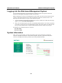
System Information
After you log on successfully, the main page displays the system information of the W406
computer, including the firmware version of the computer, the CPU system time, and system
resources, including main memory and file system usage (RAM and Flash).
3-2
W406-CE User’s Manual
Web-based Management System
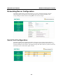
Networking/Server Configuration
The W406 computer has two network interfaces. To view or change the settings, click the
Networking item on the menu bar. After the page loads, enter the relevant details in the
corresponding text fields and then click Update to activate the changes.
Serial Port Configuration
The W406 computer has two high-performance serial ports, each of which supports RS-232,
RS-422, and RS-485. By default, each port is set for RS-232 data transmission. Each port can be
assigned a different serial interface. The updated settings take effect after the system has rebooted,
and remain in place until another update is made.
3-3
W406-CE User’s Manual
Web-based Management System
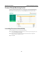
Process (Thread) Monitoring/Control
At runtime, the W406 computer manages up to 32 applications. You can use the management
system to monitor and control them. To view current processes, click the Processes item on the
main menu bar. You can kill a process by clicking the Kill button next to the process name.
Launching Processes Automatically
To set your application to start on boot up, do the following:
Step 1: Click the Processes item on the main menu bar. In the lower part of the page, there is an
area marked Automatic Launching.
Step 2: Enter the full path of the application in the first text field, and enter its arguments
(if there are any) in a separate text field.
Step 3: Click Add.
3-4
W406-CE User’s Manual
Web-based Management System
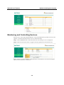
Monitoring and Controlling Services
Some services, such as ftp and telnet daemons, run in the background to provide services for user
requests. To monitor and control these services, do the following:
Step 1: Click the Services item on the main menu bar. The running services are displayed.
Step 2: Click the relevant check box to toggle a start/stop operation for the desired service.
Please note that in order to maintain normal operations, some listed services cannot be stopped.
These services do not have a check box.
3-5
W406-CE User’s Manual
Web-based Management System
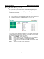
Binary/Text File Management
PC users enjoy the convenience of using Windows’ friendly windows-based file manager to
browse, delete, and organize files and directories. Moxa’s web-based management system
provides the same kind of convenience for managing files on the target computer. Click File
Manager to view the directory tree of your target computer. The file manager can be used to
perform the following operations:
y
To browse a child directory, click the name of the directory.
y
To delete a file, click the X in front of the file icon.
y
To create a child directory, click Create Directory and then follow the on-screen instructions.
y
To refresh the current directory, click Current Directory at the top of the page.
In addition, the management system offers a mechanism for uploading files. The mechanism gives
you an easy way to transfer files from your workstation to the target computer. For example, after
you build an application on the development workstation, you can use this mechanism to upload
the application to the current directory of the target computer.
Step 1:
Step 2:
Step 3:
Step 4:
Step 5:
Click Upload File. A browser window pops up.
From the pop-up browser window, click Browse to bring up a local file manager.
Browse to and select the file that you want to upload and click Open.
Navigate back to the browser window, and click OK. The system starts to upload
the file.
After the file is uploaded completely, refresh the page.
3-6
A
Appendix A
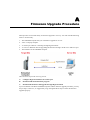
Firmware Upgrade Procedure
Moxa provides a boot loader utility for firmware upgrade or recovery. You will need the following
items to use this utility.
1. The embedded computer that you would like to upgrade or recover.
2. A PC or a laptop computer.
3. A console port cable for connecting through HyperTerminal.
4. A cross-over Ethernet cable for upgrading the firmware through a TFTP server and LAN port.
5. The firmware for the embedded computer.
There are three steps in the recovery process.
A.
Configure HyperTerminal for the console port.
B.
Download and install the TFTP program.
C.
Download the firmware and upgrade through HyperTerminal.
If you are familiar with Moxa embedded computers and the firmware upgrade procedure, you may
skip to Step C. However, we suggest that you go through all three steps to ensure the firmware
upgrades properly.
W406-CE User’s Manual
Firmware Upgrade Procedure
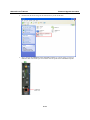
A. Configure HyperTerminal for the Console Port.
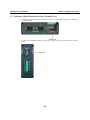
1. Connect the console port with a console port cable to your PC. The console port is located on
the bottom panel.
2. Connect your embedded computer to the power source. The power input is located on the top
panel.
A-2
W406-CE User’s Manual
Firmware Upgrade Procedure
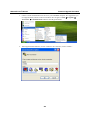
3. Launch a serial communication tool to access your embedded computer. We suggest that you
use HyperTerminal, which is built into Windows XP. Navigate to Start Æ Programs Æ
Accessories Æ Communications and then select HyperTerminal.
4. After HyperTerminal launches, choose a name for the connection, such as “W406.”
A-3
W406-CE User’s Manual
Firmware Upgrade Procedure
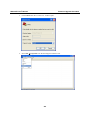
5. Click Cancel when the “Connect To” window opens.
6. Select File Æ Properties from the main HyperTerminal screen.
A-4
W406-CE User’s Manual
Firmware Upgrade Procedure
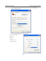
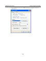
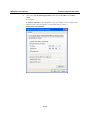
7. You can change the COM port number in the Properties window. Click Configure for
additional configuration options.
8. Configure the Port Settings with following parameters:
Bits per second: 115200
Data bits: 8
Parity: None
Stop bit: 1
Flow control: None.
Click OK to continue.
A-5
W406-CE User’s Manual
Firmware Upgrade Procedure
9. Click the Settings tab and then select VT100 (for Emulation). Click OK to complete the
configuration.
A-6
W406-CE User’s Manual
Firmware Upgrade Procedure
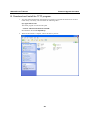
B. Download and Install the TFTP program.
1. You will need to download a free TFTP server package to upgrade the firmware for the boot
loader utility. The utility can be found at the following URL:
ftp://papa.indstate.edu/
The TFTP program is located in this path:
/winsock-1/Windows95/Daemons/TFTPD/
Download the file named tftpd32d.zip.
2. When the download is complete, extract the files to your PC.
A-7
W406-CE User’s Manual
Firmware Upgrade Procedure
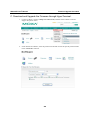
C. Download and Upgrade the Firmware through HyperTerminal.
1. Connect to Moxa’s website at http://www.moxa.com, and then select Software from the
Support drop-down menu.
2. Under Search for Software, select the product line and then choose the specific product model.
Click on Search to continue.
A-8
W406-CE User’s Manual
Firmware Upgrade Procedure
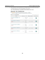
3. In the software list, select the firmware for your model. Choose the appropriate OS and then
click the download icon to start downloading the new firmware.
Note: Check the filename, it may differ from the filename shown below.
A-9
W406-CE User’s Manual
Firmware Upgrade Procedure
4. Put the latest firmware image in the same directory as the TFTP files.
5. Next, connect the LAN Port of the embedded computer to your PC using a cross-over
Ethernet cable. The LAN1 port is located on the rear panel of the embedded computer.
A-10
W406-CE User’s Manual
Firmware Upgrade Procedure
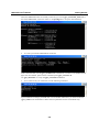
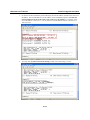
6. Press and hold down the DEL key on your PC and power on the embedded computer at the
same time. You will be guided to the boot loader utility menu, as show below.
1. In the boot loader utility, select (1) Network Configuration, and then (1) Change IP Setting
to configure IP addresses.
A-11
W406-CE User’s Manual
Firmware Upgrade Procedure
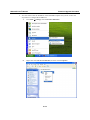
2. You will need to enter the IP address of the embedded computer and your PC. Follow the
steps below to configure the IP addresses.
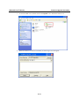
A.
From Start Æ Settings, select Network Connections.
B.
Right-click on Local Area Connection, and then select Properties.
A-12
W406-CE User’s Manual
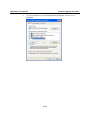
C.
Firmware Upgrade Procedure
Click the General tab and select Internet Protocol (TCP/IP), and then click on
Properties.
A-13
W406-CE User’s Manual
D.
Firmware Upgrade Procedure
Next, select Use the following IP address and enter the IP address and Subnet
mask.
For example:
IP address: 192.168.1.1 (This IP address is only an example; you may assign any IP
address of your choice as long as it’s on the same LAN as your PC.)
Subnet mask: 255.255.255.0
A-14
W406-CE User’s Manual
Firmware Upgrade Procedure
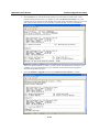
3. Go back to the boot load utility menu and assign the local IP address, and then enter the server
IP address. The local IP address is the IP address of the embedded computer. Note that the
local IP address must be on the same LAN as the server IP address. For example, if the
server IP address is 192.168.1.1, you can choose a local IP address between 192.168.1.2 to
192.168.1.254.
4. You may enter (2) Show Current IP Setting to make sure if the setting is correct.
A-15
W406-CE User’s Manual
Firmware Upgrade Procedure
5. Press the ESC key to exit the IP setting option. If you encounter a system crash, or have
problem booting up the system, we suggest you select (2) Format User Disk to solve the
problem. However, please note that all data on the disk will be erased and cannot be recovered
after a disk format. Enter Y if you would like to format the disk, or N if you would not.
When you finish formatting your disk, you may exit the boot loader utility and reboot your
computer. If you still cannot boot up your computer, perform the firmware upgrade as
described in the following steps.
6. Select (3) Firmware Upgrade, and then (1) Load from LAN1 (TFTP) to continue.
A-16
W406-CE User’s Manual
Firmware Upgrade Procedure
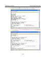
7. To start the TFPF server, double-click on the tftpd32 icon to launch the TFTP server.
8. When the TFTP server has been launched, the following screen will appear.
A-17
W406-CE User’s Manual
Firmware Upgrade Procedure
9. Go back to the boot loader utility menu and enter the file name of the firmware image.
10. The firmware upgrade will then start to run.
A-18
W406-CE User’s Manual
Firmware Upgrade Procedure
11. It will take several minutes for the firmware files to be written to your embedded computer.
Do not power off your computer!
12. When you return to command line mode, the firmware upgrade has completed. At this point,
you may reboot the embedded computer to complete the firmware upgrade or recover from the
boot loader utility.
A-19
W406-CE User’s Manual
Firmware Upgrade Procedure
13. If you cannot reboot your embedded computer even after following all the steps above, contact
Moxa’s technical support staff for further assistance.
A-20
B
Appendix B
Application Development
The mxdev library for C++ and the mxdevice library for VB.net and C# are provided to help
users develop their application on the W406 quickly and easily. The complete source code can be
found in the sample directory on the software CD.
Developing an application with VS2005
y
Open Microsoft® Visual Studio .Net 2005.
y
From the File menu, choose New Project.
y
Choose the Project Type and then select the Smart Device Application as the type of
project.
y
Fill in the project name and click OK.
y
Choose Windows CE as the target platform.
y
Select the desired project type and click OK.
y
Write your application code.
y
From the Device toolbar, choose Windows CE.Net Device.
y
From the Build menu, choose Build Project or Rebuild Project.
y
When you complete your application, upload it to the embedded computer.
y
Log on to the embedded computer. At the console prompt, execute it directly if it is a C++ or
C# file.
W406-CE User’s Manual
Application Development
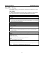
Visual C++ Library
After the SDK is installed on your development PC, the library will be available in your Visual
Studio 2005/2008 environment.
GPRS/SIM/SMS
The definition header file includes the entire library API; you can find it in the SDK installation
path “C:\Program Files\Windows CE Tools\wce600\W406-CE\Include\Armv4i\moxa”.
Opens a cellular modem handle for later use.
unsigned int cellular_modem_open(void);
Inputs:
None
Return Values:
pointer to a cellular modem handle. Return 0 on failure.
Remark:
Every cellular modem API needs the cellular modem handle parameter, so you must use the
function first before you program them.
Closes a cellular modem handle.
void cellular_modem_close(unsigned int fd);
Inputs:
<fd> the handle
Return Values:
None
Remark:
You must release the cellular modem handle resource if you don’t need to use cellular
modem APIs later.
Sends an AT command to a cellular modem and waits for a reply.
int cellular_modem_send_cmd(unsigned int fd, char *at_cmd, char *recv, int recv_size, int
timeout);
Inputs:
<fd> the cellular modem
<at_cmd> the AT command
<recv_size> maximum size of the buffer that stores replied data
<timeout> timeout in milliseconds if no response.
Outpus:
<recv> point to buffer that stores the reply
Return Values:
the number of received data, -1 indicates failure.
Remark:
Generally, you can set the timeout to be 1000~2000 milliseconds, but if you call the
function with “AT^SMGL=ALL” command. We suggest you set the timeout greater than
10000, because listing all of the SMS messages requires more time.
B-2
W406-CE User’s Manual
Application Development
Gets the signal strength of the GPRS modem.
int cellular_modem_gprs_get_signal_strength(unsigned int fd);
Inputs:
<fd> the cellular modem
Outpus:
<recv> point to buffer that stores the reply
Return Values:
1 to 99 on success, otherwise the function fails
Remark:
It is suggested to call this function periodically.
Establishes a GPRS connection to the ISP service provider.
int cellular_modem_gprs_establish_connection(unsigned int fd, char *user, char
*password);
Inputs:
<fd> the cellular modem
<user> point to the user id, null indicates empty userid.
<password> point to the user password, null indicates empty password.
Return Values:
0 on success, otherwise, the function fails
Remark:
Aborts a GPRS connection.
int cellular_modem_gprs_abort_connection(unsigned int fd);
Inputs:
<fd> the cellular modem
Return Values:
0 on success, otherwise, the function fails
Remark:
Checks the status of a GPRS connection.
int cellular_modem_gprs_check_connection_status(unsigned int fd);
Inputs:
<fd> the cellular modem
Return Values:
0 indictes the connection is on. otherwise, it is disconnected
Remark:
B-3
W406-CE User’s Manual
Application Development
Diagnoses the status of a GPRS connection and the status of the SIM card.
unsigned int cellular_modem_gprs_diagnose_status(unsigned int fd);
Inputs:
<fd> the cellular modem
Return Values:
0 indictes no error. otherwise, a 32-bit number indicating a combination of errors
Remark:
define GPRS errors, of which each stands on one of a 32-bit number
#define GPRS_ERROR_BAUDRATE_COM3
(1<<0)
#define GPRS_ERROR_BAUDRATE_COM4
(1<<1)
#define GPRS_ERROR_FLOWCONTROL
(1<<2)
#define GPRS_ERROR_PINCODE
(1<<3)
#define GPRS_ERROR_TEMPERATURE
(1<<4)
#define GPRS_ERROR_SIGNAL_STRENGTH (1<<5)
#define GPRS_ERROR_RADIOBAND
(1<<6)
#define GPRS_ERROR_MODULE
(1<<7)
If the Cellular modem temperature greater than 88 degree or less than -35 degree, the function
will return with GPRS_ERROR_TEMPERATURE.
Sets the storage base of SIM messages.
int cellular_modem_sms_set_storage_base(unsigned int fd, int mode);
Inputs:
<fd> the cellular modem
<mode> 0: on SIM card, 1: on modem module, 2: on both
Return Values:
0 on success, otherwise, the function fails
Remark:
Gets the storage base of SIM messages.
int cellular_modem_sms_get_storage_base(unsigned int fd);
Inputs:
<fd> the cellular modem
Return Values:
0: on SIM card, 1: on modem module, 2: on both, otherwise, the function fails
Remark:
Gets the number of stored messages allowed out of the maximum space.
int cellular_modem_sms_get_message_count(unsigned int fd, int *maximum);
Inputs:
<fd> the cellular modem
Outputs:
<maximum> pointer to the maximum number of messages allowed
Return Values:
the number of stored messages, otherwise, a negative value indicates a failure
Remark:
B-4
W406-CE User’s Manual
Application Development
Sends a SMS message to a specific phone number.
int cellular_modem_sms_send_message(unsigned int fd, unsigned int msg_mode, SMSMSG
*psms);
Inputs:
<fd> the cellular modem
<msg_mode> 0: message in text, 1: message in PDU
<psms> point to the message
Return Values:
0 on success, otherwise, the function fails
Remark:
#define MAX_SMS_BYTES
512
typedef struct _SMSMSG
{
unsigned int
been_read;
char msg_date[12];
char msg_time[20];
char phone_number[20];
unsigned int msg_length;
char msg_text[MAX_SMS_BYTES];
} SMSMSG, *PSMSMSG;
If you like to use PDU mode to send your SMS message, you must construct your PDU data into
the “SMSMSG.msg_text” field with exact length “SMSMSG.msg_length”.
Receives an indexed SMS message.
int cellular_modem_sms_recv_message(unsigned int fd, int index, unsigned int msg_mode,
SMSMSG *psms);
Inputs:
<fd> the cellular modem
<index> the index to the message pool
<msg_mode> 0: message in text, 1: message in PDU
<psms> point to the message
Return Values:
0 on success, otherwise, the function fails
Remark:
#define MAX_SMS_BYTES
512
typedef struct _SMSMSG
{
unsigned int
been_read;
char msg_date[12];
char msg_time[20];
char phone_number[20];
unsigned int msg_length;
char msg_text[MAX_SMS_BYTES];
} SMSMSG, *PSMSMSG;
If you like to use PDU mode to receive your SMS message, you must destruct the
“SMSMSG.msg_text” field to extract the message body.
B-5
W406-CE User’s Manual
Application Development
Deletes an indexed SMS message.
int cellular_modem_sms_delete_message(unsigned int fd, int index);
Inputs:
<fd> the cellular modem
<index> the index to the message pool
Return Values:
0 on success, otherwise, the function fails
Remark:
Gets the SIM card status.
int cellular_modem_sim_get_sim_card_status(unsigned int fd);
Inputs:
<fd> the cellular modem
Return Values:
0 : ready, okay to use
1 : no sim card, (or loose)
2 : PIN, wait for the pin code for authentication
3 : PUK, three times of wrong pin codes
otherwise, the function fails
Remark:
When the SIM card status is set to PIN (2), this function retrieves the available PIN code attempt
count.
If the SIM card status is set to PUK (3), this function gets the available PUK code attempt count.
int cellular_modem_sim_get_pin_attempt_count(unsigned int fd);
Inputs:
<fd> the cellular modem
Return Values:
the attempted count left of PIN/PUK code authentication. otherwise, a negative value
indicates a failure
Remark:
When the SIM card status is set to PIN (2), this function authenticates a PIN code. If the correct
code is entered the status will be set back to ready (0).
int cellular_modem_sim_authenticate_pin_code(unsigned int fd, char *pin_code);
Inputs:
<fd> the cellular modem
<pin_code> point to the PIN code
Return Values:
0 on success, otherwise, the function fails
Remark:
B-6
W406-CE User’s Manual
Application Development
When the SIM card status is PUK (3), this function changes the status to PIN (2).
If this fails, the SIM card will be locked.
int cellular_modem_sim_unlock_pin_code(unsigned int fd, char *passwd, char
*new_pin_code);
Inputs:
<fd> the cellular modem
<passwd> point to the PUK passwd code
<new_pin_code> point to a new PIN code
Return Values:
0 on success, otherwise, the function fails
Remark:
Gets the PIN code enable status of the SIM card.
int cellular_modem_sim_get_pin_enable_status (unsigned int fd);
Inputs:
<fd> the cellular modem
Return Values:
0 : PIN code disabled
1 : PIN code enabled
otherwise, the function fails
Remark:
When the SIM card status is ready (0) and the PIN code is enabled, this function assigns a PIN
code to the SIM card.
int cellular_modem_sim_assign_pin_code(unsigned int fd, char *old_pin_code, char
*new_pin_code);
Inputs:
<fd> the cellular modem
<old_pin_code> point to the old PIN code
<new_pin_code> point to the new PIN code
Return Values:
0 on success, otherwise, the function fails
Remark:
When the SIM card status is ready (0), this function enables or disables PIN code authentication.
int cellular_modem_sim_enable_pin_code(unsigned int fd, char *pin_code, int enable);
Inputs:
<fd> the cellular modem
<pin_code> point to the PIN code password
<enable> 1: enable PIN code, 0: disable PIN code
Return Values:
0 on success, otherwise, the function fails
Remark:
B-7
W406-CE User’s Manual
Application Development
Get the modem module temperature.
int cellular_modem_gprs_get_module_temperature(unsigned int fd)
Inputs:
<fd> the cellular modem
Return Values:
the tempture of GPRS module
Remark:
UART
Gets the UART interface.
DWORD uart_getmode(int port);
Inputs:
<port> the serial port number.
Return Values:
0 : RS-232
1 : RS485-2W
2 : RS422
3 : RS485-4W
otherwise, the function fails
Remark:
For example, user uart_getmode(2) to retrieve the interface of COM2:
Sets the UART interface.
BOOL uart_setmode(int port, int mode);
Inputs:
<port> the serial port number.
<mode> the interface parameter.
0 : RS-232
1 : RS485-2W
2 : RS422
3 : RS485-4W
Return Values:
TRUE indicates success, FALSE indicates failed.
Remark:
For example, user uart_getmode(2) to retrieve the interface of COM2:
DIO
Opens a DIO handle for later use.
HANDLE mxdio_init(void);
Inputs:
none
Return Values:
pointer to a DIO handle. Return 0 on failure.
Remark:
Every DIO API needs the handle parameter, so you must use the function first before you
program them.
B-8
W406-CE User’s Manual
Application Development
Closes the DIO handle.
void mxdio_stop(HANDLE hDIO);
Inputs:
<hDIO> the DIO handle
Return Values:
None
Remark:
Sets one of the DOUT outputs.
int mxdio_set_dout(HANDLE hDIO, unsigned int port, unsigned int data);
Inputs:
<hDIO> the DIO handle
<port> the port index, from 0 to 3 mapping to DO0~DO3
<data> 1: HIGH, 0: LOW
Return Values:
0 on success, otherwise, the function fails
Remark:
Gets one of the DIN inputs.
int mxdio_get_din(HANDLE hDIO, unsigned int port);
Inputs:
<hDIO> the DIO handle
<port> the port index, from 0 to 3 mapping to DI0~DI3
Return Values:
1 indicates HIGH, 0 indicates LOW
Remark:
Gets one of DOUT outputs.
int mxdio_get_dout(HANDLE handle_dio,unsigned int port);
Inputs:
<hDIO> the DIO handle
<port> the port index, from 0 to 3 mapping to DO0~DO3
Return Values:
1 indicates HIGH, 0 indicates LOW
Remark:
B-9
W406-CE User’s Manual
Application Development
Watchdog
Opens a watchdog handle for later use.
HANDLE watchdog_init(DWORD dwRefreshPeriod);
Inputs:
<dwRefreshPeriod> the watchdog refresh time interval in milliseconds..
Return Values:
the watchdog handle, INVALID_HANDLE_VALUE indicates failure.
Remark:
After calling the watchdog_init(), you must call watchdog_refresh() in the specified
time(dwRefreshPeriod) or the system will be triggered rebooting.
Watchdog refresh function call.
BOOL watchdog_refresh(HANDLE hWdg, DWORD dwRefreshPeriod);
Inputs:
<hWdg> the watchdog handle from watchdog_init() returned
Return Values:
TRUE indicates the watchdog refresh succeed, FALSE indicates refresh failure.
Remark:
Closes the watchdog handle.
BOOL watchdog_release(HANDLE hWdg);
Inputs:
<hWdg> the watchdog handle watchdog_init() returned
Return Values:
TRUE indicates the watchdog refresh succeed, FALSE indicates refresh failure.
Remark:
Buzzer
Turns on the buzzer.
void mxbeep_on(void);
Inputs:
None
Return Values:
None
Remark:
Turns off the buzzer.
void mxbeep_off(void);
Inputs:
None
Return Values:
None
Remark:
B-10
W406-CE User’s Manual
Application Development
Visual C++ Examples
The C++ examples are available on the software CD for your reference.
Net Compact Framework Library
For .Net programming, MOXA also provides a .Net Compact Framework library.
GPRS/SIM/SMS
The definition header file includes the entire library APIs, you can find it in the Software
CD
Opens a cellular modem.
Class Name: GPRS
Method: bool Open()
Inputs:
None
Return Values:
True indicates success, False means failure.
Remark:
You must open the cellular modem first before you use the other GPRS method.
Closes a cellular modem.
Class Name: GPRS
Method: void Close()
Inputs:
none
Return Values:
none
Remark:
You must close the cellular modem handle resource if you don’t need to use cellular modem
APIs later.
Sends AT command to the cellular modem directly and gets the responded string.
Class Name: GPRS
Method: int SendATCommand(string atCmd, ref string szRecv, uint timeout)
Inputs:
<atCmd> AT command string; Remember to concatenate the “\r” in the end of string
<szRecv> The Responded string
<timeout> Timeout in milliseconds.
Return Values:
Number of bytes returned, otherwise the function fails
Remark:
B-11
W406-CE User’s Manual
Application Development
Gets the signal strength of the GPRS modem,
Class Name: GPRS
Method: int GetSignalStrength()
Inputs:
none
Return Values:
1 to 99 on success, otherwise the function fails
Remark:
It is suggested to call this function periodically.
Establishes a GPRS connection to the ISP service provider.
Class Name: GPRS
Method:
int Connect()
int Connect(string user, string password)
Inputs:
<user> the user id string
<password> the password string
Return Values:
0 on success, otherwise, the function fails
Remark:
Aborts a GPRS connection.
Class Name: GPRS
Method: int Disconnect()
Inputs:
None
Return Values:
0 on success, otherwise, the function fails
Remark:
Checks the status of a GPRS connection.
Class Name: GPRS
Method: ConnectionState GetConnectionStatus()
Inputs:
none
Return Values:
0 indictes the connection is on. otherwise, it is disconnected
Remark:
public enum ConnectionState
{
Connected = 0,
Disconnected
}
B-12
W406-CE User’s Manual
Application Development
Diagnoses the status of a GPRS connection and the status of the SIM card.
Class Name: GPRS
Method: int Diagnose()
Inputs:
none
Return Values:
0 indictes no error. otherwise, a 32-bit number indicating a combination of errors
Remark:
define GPRS errors, of which each stands on one of a 32-bit number
const GPRS_ERROR_BAUDRATE_COM3
(1<<0)
const GPRS_ERROR_BAUDRATE_COM4
(1<<1)
const GPRS_ERROR_FLOWCONTROL
(1<<2)
const GPRS_ERROR_PINCODE
(1<<3)
const GPRS_ERROR_TEMPERATURE
(1<<4)
const GPRS_ERROR_SIGNAL_STRENGTH
(1<<5)
const GPRS_ERROR_RADIOBAND
(1<<6)
const GPRS_ERROR_MODULE
(1<<7)
If the Cellular modem temperature greater than 88 degree or less than -35 degree, the function
will return with GPRS_ERROR_TEMPERATURE.
Gets the number of stored messages allowed out of the maximum space.
Class Name: GPRS
Method: int GetSMSMessagesCount (ref int)
Inputs:
<fd> the cellular modem
Outputs:
<maximum> pointer to the maximum number of messages allowed
Return Values:
The number of stored messeages. otherwise, a negative value indicates a failure
Remark:
Gets the current SMS storage base.
Class Name: GPRS
Method: int GetSMSStorageBase ()
Inputs:
none.
Return Values:
Storage base number in “StorageBase” type.
Remark:
public enum StorageBase
{
SIMCard = 0,
CellularModule,
Both
}
B-13
W406-CE User’s Manual
Application Development
Sets the SMS storage base.
Class Name: GPRS
Method: int SetSMSStorageBase(StorageBase mode)
Inputs:
<mode> Storage base number in “StorageBase” type.
Return Values:
0 on success, otherwise the function fails
Remark:
public enum StorageBase
{
SIMCard = 0,
CellularModule,
Both
}
Sends an SMS message to a specific phone number.
Class Name: GPRS
Method: int SendSMS(uint msg_mode, ref SMSMSG pmsg)
Inputs:
<msg_mode> 0: message in text, 1: message in PDU
<psms> SMS message structure
Return Values:
0 on success, otherwise, the function fails
Remark:
public struct SMSMSG
{
public uint been_read;
public string msg_date;
public string msg_time;
public string phone_number;
public uint msg_length;
public string msg_text;
}
If you like to use PDU mode to send your SMS message, you must construct your PDU data into
the “SMSMSG.msg_text” field with exact length “SMSMSG.msg_length”.
B-14
W406-CE User’s Manual
Application Development
Receives an indexed SMS message.
Class Name: GPRS
Method: int RecvSMS(int index, uint msg_mode, ref SMSMSG pmsg)
Inputs:
<index> the index to the message pool
<msg_mode> 0: message in text, 1: message in PDU
<psms> point to the message
Return Values:
0 on success, otherwise, the function fails
Remark:
public struct SMSMSG
{
public uint been_read;
public string msg_date;
public string msg_time;
public string phone_number;
public uint msg_length;
public string msg_text;
}
If you like to use PDU mode to receive your SMS message, you must destruct the
“SMSMSG.msg_text” field to extract the message body.
Deletes an indexed SMS message.
Class Name: GPRS
Method: int DeleteSMS(int);
Inputs:
<index> the index to the message pool
Return Values:
0 on success, otherwise, the function fails
Remark:
B-15
W406-CE User’s Manual
Application Development
Gets the status of the SIM card.
Class Name: GPRS
Method: SIMCardState GetSIMCardStatus();
Inputs:
none
Return Values:
0 : ready, okay to use
1 : no sim card, (or loose)
2 : PIN, wait for the pin code for authentication
3 : PUK, three times of wrong pin codes
otherwise, the function fails
Remark:
public enum SIMCardState
{
Ready = 0,
NoSIMCard,
NeedPINCode,
NeedPUKCode
}
When the SIM card status is set to NeedPINCode (2), this function retrieves the available PIN
code attempt count. If the SIM card status is set to NeedPUKCode (3), this function gets the
available PUK code attempt count.
Class Name: GPRS
Method: int GetPINAttemptCount()
Inputs:
none
Return Values:
The attempted count left of PIN/PUK code authentication. otherwise, a negative value
indicates a failure
Remark:
B-16
W406-CE User’s Manual
Application Development
When the SIM card status is set to NeedPINCode (2), this function authenticates a PIN code.
Then the status will be set back to ready (0).
Class Name: GPRS
Method: int InputPINCode(string pin_code);
Inputs:
<pin_code> the PIN code string
Return Values:
0 on success, otherwise, the function fails
Remark:
When the SIM card status is NeedPUKCode (3), this function changes the status to
NeedPINCode (2).
If it fails, the SIM card is locked.
Class Name: GPRS
Method: int UnlockSIMCard(string puk_code, string new_pin_code);
Inputs:
<puk_code> the PUK passwd code string
<new_pin_code> the new PIN code string
Return Values:
0 on success, otherwise, the function fails
Remark:
Gets the PIN code enable status of the SIM card:
Class Name: GPRS
Method: int GetPinEnableStatus();
Inputs:
<fd> the cellular modem
Return Values:
0 : PIN code disabled
1 : PIN code enabled
otherwise, the function fails
Remark:
Gets the PIN code enable status of the SIM card.
Class Name: GPRS
Method: int PinEnable(string pin_code, bool enable);
Inputs:
<pin_code> the PIN code password
<enable> true to enable PIN code authentication, false to disable the PIN code authentication
Return Values:
0 on success, otherwise, the function fails
Remark:
B-17
W406-CE User’s Manual
Application Development
When the SIM card status is ready (0) and the PIN code is enabled, this function assigns a PIN
code to the SIM card.
Class Name: GPRS
Method: int ChangePINCode(string old_pin_code, string new_pin_code);
Inputs:
<old_pin_code> the old PIN code string
<new_pin_code> the new PIN code string
Return Values:
0 on success, otherwise, the function fails
Remark:
Gets the modem module temperature.
Class Name: GPRS
Method: int GetGPRSModuleTemperature();
Inputs:
none
Return Values:
the tempture of GPRS module
Remark:
UART
Sets the UART interface.
Class Name: SerialInterface
Method: void SetComPortInterface(string port, SerialMode mode);
Inputs:
<port> serial port name string, e.g. COM1:, COM2:, $device\COM12
<mode> the interface number of serial port
Return Values:
none
Remark:
public enum SerialMode : byte
{
RS232_MODE = 0x0,
RS485_2WIRE_MODE = 0x1,
RS422_MODE = 0x2,
RS485_4WIRE_MODE = 0x3
}
B-18
W406-CE User’s Manual
Application Development
DIO
Sets one of the DOUT outputs.
Class Name: DigitalOutput
Method: bool Set(int port, int data);
Inputs:
<port> the port index, from 0 to 3 mapping to DO0~DO3
<data> 1 : HIGH, 0 : LOW
Return Values:
true on success, false, the function fails
Remark:
Get one of the DIN inputs.
Class Name: DigitalInput
Method: int Get(int port);
Inputs:
<port> the port index, from 0 to 3 mapping to DI0~DI3
Return Values:
1 indicates HIGH, 0 indicates LOW
Remark:
Gets one of DOUT outputs.
Class Name: DigitalOutput
Method: int Get(int port);
Inputs:
<port> the port index, from 0 to 3 mapping to DO0~DO3
Return Values:
1 indicates HIGH, 0 indicates LOW
Remark:
Watchdog
Starts up the watchdog.
Class Name: Watchdog
Method: bool start (uint dwRefreshPeriod);
Inputs:
<dwRefreshPeriod> the watchdog refresh time interval in milliseconds.
Return Values:
True on success, false indicates failure.
Remark:
After calling the start(), you must call refresh() in the specified time(dwRefreshPeriod) or
the system will be triggered rebooting.
B-19
W406-CE User’s Manual
Application Development
Watchdog refresh function call.
Class Name: Watchdog
Method: bool refresh();
Inputs:
none
Return Values:
true indicates the watchdog refresh succeed, false indicates refresh failure.
Remark:
Closes the watchdog handle.
Class Name: Watchdog
Method: bool close();
Inputs:
None
Return Values:
True indicates the watchdog refresh succeed, false indicates refresh failure.
Remark:
Buzzer
Turns on the buzzer.
Class Name: Buzzer
Method: void BeepOn();
Inputs:
none
Return Values:
none
Remark:
Turns off the buzzer.
Class Name: Buzzer
Method: void BeepOff();
Inputs:
none
Return Values:
none
Remark:
B-20
W406-CE User’s Manual
Application Development
Visual C# Examples
A device .Net CF 2.0 class library (mxdevice.dll) is provided to simplify application development
with Visual Studio 2005 tools. This library covers the .Net CF Class Library for the buzzer and
digital I/O devices. To link the library with your Visual Studio 2005 project environment, perform
the following steps from your Visual Studio 2005 tool:
1. Copy the library file mxdevice.dll to any folder on your local disk.
This file can be found on the product CD in the folder \sdk\dot Net Compact Framework
Library, or the file can be downloaded from the FTP site listed in the NOTE at the bottom of this
page.
2. Open the Visual Studio 2005 IDE tool, and then add a new C# Smart device console
application.
3. Enter the project name and location path.
4. In the Solution Explorer View, add mxdevice.dll to the reference section.
5. Click OK.
ATTENTION
1. The programming examples for Moxa embedded computers are frequently updated. The
latest examples can be downloaded from the following FTP site:
ftp://esource.moxa.com/moxasys/WinCE_Examples/C#.
2. You may need to copy the “mxdevice.dll” within the example when you try to execute the
program.
B-21