1
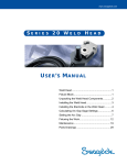
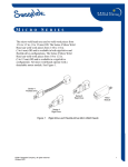
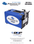
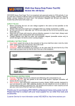
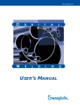
E ME
SWEERL DI IENSG S4 Y0S T W
C
L D
H
E A D
Swagelok series 40 welding system components deliver
consistent, precise welds for outside diameters from 1 1/2
to 4 in. (38,1 to 101,6 mm).
A dc motor in the weld head drives a rotor, which revolves
the tungsten electrode around the weld joint. Optical
circuitry in the weld head sends precise feedback to the
power supply to control the speed of the rotor.
All moving parts in the weld head are mounted in
low-friction devices to provide smooth,
consistent operation.
A spring-loaded, floating brush maintains contact with
approximately two-thirds of the circumference of the rotor.
This configuration ensures consistent, uniform electrical
conductance to the rotor and electrode.
©2000 Swagelok Company, all rights reserved
December 2000
Figure 1
Series 40 Weld Head
1
Series 40 Weld Head
Unpacking the Weld Head
Components
The weld head assembly and tool package are packaged in
a foam-lined shipping container. Perform the following
steps when your Swagelok series 40 weld head arrives.
1. Inspect the container for damage.
2. Remove the components from the container.
3. Check the items for any damage.
4. Verify that the weld head serial number matches the
serial number on the shipping container.
5. Record the model and serial numbers, and
the delivery dates on page 7 of the Regulatory Module.
2
©2000 Swagelok Company, all rights reserved
December 2000
Series 40 Weld Head
Installing the Weld Head
Electrode
Fixture
Work
The weld head assembly has four connectors that plug into
the power supply. See Figure 2.
Weld Head
Shielding
Gas
The four connectors on the cable are:
•
fixture
•
electrode (red)
•
work (green)
•
weld head shielding gas.
Figure 2
Weld Head Assembly
Connect the four connectors to the rear panel of the power
supply by performing the following steps
(see Figure 3):
1. Locate the weld head assembly.
2. Align the notch on the multi-pin connector with the
small tab in the mating socket on the rear panel labeled
FIXTURE. Insert the connector in the socket. Turn the
connector sleeve clockwise by hand until it is tight.
This connection provides the control signals to drive
the weld head.
3. Insert and fully seat the red connector into the socket on
the rear panel labeled ELECTRODE. Twist the
connector 1/4-turn clockwise to lock it into place. This
connection is the negative (-) terminal of the weld head.
4. Insert the green connector into the socket on the rear
panel labeled WORK. Twist the connector 1/4-turn
clockwise to lock it into place. This connection is the
positive (+) terminal of the weld head.
5. Insert the weld head shielding gas connector into the
Swagelok Quick-Connect stem labeled TO WELD
HEAD. Ensure that the connector is firmly attached.
This connection provides shielding gas to the weld
head through a solenoid valve in the power supply.
©2000 Swagelok Company, all rights reserved
December 2000
Figure 3
Weld Head Connectors
Caution!
Ensure that the fixture
connector is fully seated in
the mating socket and the
threaded sleeve is tight.
Note: The weld head shielding gas
connector must be a single-end shut-off
(SESO) Swagelok Quick-Connect stem
(SS-QC4-S-400).
3
Series 40 Weld Head
Selecting the Electrode
Electrode length depends on the desired arc gap and
outside diameter of the work piece being welded. To
select the correct electrode use the Calculating Tungsten
Electrode Length formula. Once you have the correct
length calculated either select an electrode from stock using
the Electrode Selection Table or place a special order.
Tungsten Electrode Length Calculation
To determine the tungsten electrode length for a specific arc gap, use the formula below:
(Rotor OD ÷ 2) − (Tube OD ÷ 2) − Arc Gap = Electrode Length
A
B
Rotor OD
Tube
OD
C
Arc Gap
Electrode
Length
Rotor OD = 6.850 in. (173,99 mm)
Figure 4
Electrode Length Calculation Parameters
Example No. 1: (1.5 in. to 1.5 in. tube butt weld)
Rotor OD
A= 6.850 in.
Tube outside diameter
B= 1.500 in.
Desired arc gap
C= 0.060 in.
(6.850 ÷ 2) − (1.500 ÷ 2) − 0.060 in. = 2.615 in.
Example No. 2: (38,1 mm to 38,1 mm tube butt weld)
Rotor OD
A = 173,99 mm
Tube outside diameter
B = 38,10 mm
Desired arc gap
C = 1,52 mm
(173,99 ÷ 2) − (38,10 ÷ 2) − 1,52 mm = 66,425 mm
4
©2000 Swagelok Company, all rights reserved
December 2000
Series 40 Weld Head
Table 1
Electrode Selection for 0.060 in. Arc Gap
Electrode Part No.
Component
OD
SWS-C.094-2.615-P
1.5 in.
SWS-C.094-2.365-P
2.0 in.
SWS-C.094-2.115-P
2.5 in.
SWS-C.094-1.865-P
3.0 in.
SWS-C.094-1.615-P
3.5 in.
SWS-C.094-1.365-P
4.0 in.
Electrode
Length (L)
2.615 in.
(66,40 mm)
2.365 in.
(60,07 mm)
2.115 in.
(53,72 mm)
1.865 in.
(47,37 mm)
1.615 in
(41,02 mm)
1.365 in
(34,67 mm)
Electrode
Diameter
(D)
0.094 in.
(2,39 mm)
0.094 in.
(2,39 mm)
0.094 in.
(2,39 mm)
0.094 in.
(2,39 mm)
0.094 in.
(2,39 mm)
0.094 in.
(2,39 mm)
Note: Auto generated programs are exact
lengths. You may substitute another length
that is within 0.005 in.
Electrode Geometry
This illustration shows the electrode shape Swagelok
suggests. Properly ground electrodes provide consistent,
repeatable welds. Pre-ground electrodes are available from
your Swagelok representative. See your parts list for
ordering information.
The electrode part numbers are assigned as follows:
SWS – X.###
-
#.###
-
### -
P
Figure 5
Electrode
Diameter
Material Designator
C = Ceriated
T = Thoriated
Electrode
Length
Tungsten Electrode
Tip Diameter Package
Designator
The ceriated electrode material type is a mixture of
98 % tungsten and 2 % cerium and is commonly referred to
as “2 % ceriated.” This electrode type has demonstrated
improved arc starting performance over the 2 % thoriated
type, particularly when using purified shielding gas.
©2000 Swagelok Company, all rights reserved
December 2000
5
Series 40 Weld Head
Installing the Electrode
1. With the weld head in the open position, press JOG on
the operator panel until the tungsten electrode is in the
position shown in Figure 6.
Electrode
Set Screw
2. Loosen the electrode set screw. Remove the electrode if
you are replacing it.
3. Insert the new electrode until it is flush with the outside
edge of the rotor.
4. Tighten the electrode set screw to secure
the electrode.
5. Press HOME on the operator front panel to return rotor
to the home position.
Electrode
Outside Edge
Of Rotor
Figure 6
Electrode Installation
Caution!
Do not jog or move the rotor
unless the electrode is
clamped in place.
6
©2000 Swagelok Company, all rights reserved
December 2000
Series 40 Weld Head
Preparing the Work
It is important to prepare the tube pieces properly before
welding. Refer to Figure 7.
Tubing must be square and burr-free to ensure repeatable,
high-quality autogenous fusion welds.
Cut the tubing to length with a hacksaw or tube cutter. Face
the tube ends with a lathe or a portable facing tool. Deburr the
ends, making sure that both the inside and outside diameters
are square and burr-free. Clean the tube ends using an
appropriate solvent.
Minimize the chance of a poor quality weld by following
these guidelines:
•
Tube ends must be square.
•
Tube ends must not have a wall thickness variation
exceeding ± 15 % of nominal.
•
Tube ends must be burr-free.
•
Tube ends must be free of any rust, grease, oil, paint,
or other surface contaminates.
Method
Result
Burrs in
Flow Path
Burrs
Hack Saw Cut
Gap
End Rolled by Cutter
Blade and Roller
Irregular Tube
Diameter
Tube Cutter
Burrs
Face Perpendicular
to Axis
Reduced Flow Area
Smooth Transition
at Wall Faces
Tube Facing Tool
Square Corners
No Gaps
Figure 7
©2000 Swagelok Company, all rights reserved
December 2000
Tube Preparation
7
Series 40 Weld Head
Operating the Weld Head
Operate the weld head using the following parameters:
Series 40
3
Shield gas flow rate std ft /hr
(std L/min)
30 to 50①
(14 to 23)
Prepurge and Postpurge
minimum time in seconds
45②
Start Power
Normal
Maximum Recommended
Average Amps
100 A
①
Set flow to higher rates when welding at high current rates.
②
Flow should be continuous for cooling when welding at high current rates.
Collet Installation
1. Select the appropriate set of collets according to the tube
OD of the tubing to be welded.
2. Remove the four screws holding the collets on each side
of the weld head.
3. Install the selected collet.
Screws
(Qty. 4)
4. Reinstall the screws.
Figure 8
Installing the Collet
Work Piece Alignment
1. Open the window cover.
2. Open one of the fixture side plates.
3. Insert the first work piece aligning it with the
tungsten electrode.
4. Close and latch the fixture side plate.
5. Open the other fixture side plate.
6. Insert the second work piece and butt the weld
ends together.
7. Close and latch the fixture side plate.
8. Inspect the alignment by looking through the window
cover to verify that the two work pieces are centered on
the tungsten electrode.
8
Figure 9
Aligning the Work Piece with
the Electrode
©2000 Swagelok Company, all rights reserved
December 2000
Series 40 Weld Head
Latch Tension Adjustment
1. Adjust the latch adjustment screws so that the latch is in
position to exert appropriate tension on the tube.
Latch
Adjustment Screws
Figure 10 Adjusting the Latch Tension
Weld Head Mounting
1. Bolt the mounting bracket to the top of the bench.
2. Thread the power cord through the opening of the
mounting bracket and seat the weld head in the position
shown in Figure 11.
Figure 11 Mounting the Weld Head
Note: The weld head may be mounted
as illustrated or turned 90°.
©2000 Swagelok Company, all rights reserved
December 2000
9
Series 40 Weld Head
Performing Daily Maintenance
To keep your Swagelok welding system (SWS) equipment
in proper working order, you must perform daily
maintenance on the system components.
Store the weld head in a clean, dry place.
Note: If you experience problems while
performing the procedures in this
section, refer to Troubleshooting or
contact your Swagelok representative.
At the start of each workday remove dirt, carbon, and vapor
deposits from the weld head rotor area with a clean, soft
cloth and a solvent such as isopropyl alcohol.
Rotor Area
Figure 12 Inspect Exposed Surfaces of
the Weld Head
WARNING!
DISCONNECT THE
WELD HEAD FROM THE
POWER SUPPLY
BEFORE PERFORMING
MAINTENANCE.
10
©2000 Swagelok Company, all rights reserved
December 2000
Series 40 Weld Head
Performing Periodic Maintenance
This section describes the procedures necessary for
maintaining the weld head after every 400 to
500 welds.
Parts that are found to be defective during this procedure
should be replaced. For detailed part drawings and ordering
information, refer to the Part Drawings beginning at the
end of this manual. Spare parts are available through your
Swagelok representative.
Caution!
Do not use lubricants inside
the weld head.
Weld Head Timing Check Program
1.
2.
3.
4.
5.
Select PROG/CREATE.
Select MANUAL ENTRY, then press ENTER.
Select LEVELS ONLY, then press ENTER.
Enter 2 levels, then press ENTER.
Enter a programmer name. Typically it would be
your name.
6. Enter the Side 1 Tube Diameter (40), then press ENTER.
7. Select 40H from the Weld Head pick list.
8. Using Table 2, enter the following parameters.
Table 2
Parameters
Parameter
Start Power
Start Current
Rotor Delay
Prepurge
Postpurge
Downslope
Entry
Normal
20
0
5
5
0
9. Using Table 3, enter the following parameters for level
1 and level 2.
Table 3 Level 1 and Level 2 Parameters
Parameter
Impulse
Maintenance
Weld Time
Ramp
Pulse Rate
Pulse Width
Speed Hi
Speed Lo
Level 1 Setting
2.0
2.0
60
0
1
50
2.00
2.00
Level 2 Setting
2.0
2.0
15
0
1
50
0.00
0.00
10. Press WELD.
11. Select SAVE TO MEMORY, then press ENTER.
12. Enter the procedure name (Timing Test), then
press ENTER.
©2000 Swagelok Company, all rights reserved
December 2000
11
Series 40 Weld Head
Weld Head Timing Test
1. Select WELD/TEST.
2. Press START.
3. After verifying the screen displays “WELD HEAD IS
CLEAR TO ROTATE”, press ENTER.
4. Verify the rotor completes two revolutions then check
that no part of the rotor is exposed after it stops. See
Figure 13.
5. If the rotor does not complete the revolutions
and stop correctly, contact your
Swagelok representative.
Correct
Incorrect
Figure 13 Rotor Position
WARNING!
THE ROTOR WILL ROTATE
ONE REVOLUTION TO HOME
POSITION 15 SECONDS
AFTER COMPLETING THE
TWO REVOLUTIONS
12
©2000 Swagelok Company, all rights reserved
December 2000
Series 40 Weld Head
Weld Head Cleaning and Inspection
This section describes how to disassemble the weld head
and rotor.
Weld Head
To disassemble the weld head, follow these steps:
1. Blow any loose material from the weld head assembly
with clean, low-pressure air.
2. Remove the four screws from the left side plate.
See Figure 14.
3. Using a flat-bladed screwdriver, evenly pry the left
fixture side plate off of the weld housing being careful
not to damage ends of threaded alignment studs.
Screws
(Qty. 4)
Figure 14 Removing the Left
Side Plate
Note: As you remove the screws from the
weld head organize them so that you can
reinstall them in their original holes upon
reassembly.
4. Remove the long motor cover screws and the motor
cover end screws. See Figure 15.
Motor Cover
Screws – Long
(Qty. 2)
Motor Cover
End Screws
(Qty. 2)
Figure 15 Removing the Motor Cover
5. Remove the four weld head housing screws from the
housing. Using a flat blade screwdriver, carefully
separate the brush side from the gear side.
See Figure 16.
Weld Head Housing
Screws (Qty. 4)
6. Carefully separate the weld head housing halves so that
internal components, such as the ground pin insulators
and fixture pin insulator are not damaged.
See Figure 16.
Figure 16 Disassembling the Weld Head
Housing
©2000 Swagelok Company, all rights reserved
December 2000
13
Series 40 Weld Head
Brush
1. Remove the three brush screws and the two clamping
plate screws.
Brush Screws
(Qty. 3)
2. Remove the brush from the brush side of the
housing assembly. See Figure 17.
3. Inspect and clean the brush using the following steps:
•
Check the brush for excessive wear. Replace
if necessary.
•
Remove any oxidation from the brush
surface and brush clamp plate with a nylon
abrasive pad.
•
Turn the brush over and remove any oxidation from
the area that contacts the brush clamp plate with a
nylon abrasive pad.
•
Remove the residue left by the abrasive pad using
isopropyl alcohol and a lint-free pad.
•
Remove residue from the brush groove with
isopropyl alcohol and a lint-free pad.
4. Reinstall the brush making sure the springs are
fully seated in the brush housing.
Clamping
Plate Screws
(Qty. 2)
Figure 17 Removing the Brush
Note: The brush clamp plate is attached
with two Torx Plus IP-8 screws. Use a
Torx Plus T8 wrench to remove.
Caution!
Be careful not to strip the
heads or screw threads.
Note: The brush should demonstrate a
spring action if installed properly.
5. Screw the two short screws into the brush
clamp plate.
6. Screw the three long screws into the brush housing.
14
©2000 Swagelok Company, all rights reserved
December 2000
Series 40 Weld Head
Rotor
1. Inspect the gears for wear and replace if damaged
by referring to the Gear Side Assembly drawing on
page 22.
Note: Make any necessary gear
replacements before reinstalling
the rotor.
2. Remove the rotor from the gear side of the
housing assembly. See Figure 18.
3. Place the rotor on a clean, dry surface.
4. Inspect the rotor bearing assemblies for wear and
damage. Contact your Swagelok representative if
replacement is necessary.
5. If the rotor bearing assemblies are dirty, clean them with
isopropyl alcohol.
6. Inspect the rotor for dirt and other deposits. Remove dirt
or other deposits with a nylon abrasive pad.
Figure 18 Removing the Rotor
7. Remove residue from the rotor track with isopropyl
alcohol and a lint-free pad.
8. Remove the actuator tab. Inspect it for
excessive wear. Replace if necessary.
9. Remove dirt or other deposits from the actuator tab with
a nylon abrasive pad.
10. Remove residue left by the nylon abrasive pad from the
actuator tab with isopropyl alcohol and a lint-free pad.
11. Reinstall the actuator tab.
12. Reinstall the rotor onto the rotor track making sure that
it is centered.
Weld Head Reassembly
1. Reinstall the brush side assembly onto the gear
side assembly.
2. Replace the left side of the motor cover making sure the
cable cover is seated in the stress reliever.
Note: If the fixture side plate screws
thread into the alignment studs and
cause both to rotate without tightening,
insert an Allen wrench into the alignment
stud to keep it in place while you finish
tightening the fixture side plate screws.
3. Replace the left side fixture plate.
©2000 Swagelok Company, all rights reserved
December 2000
15
Series 40 Weld Head
Home Sensor Adjustment
Test the home sensor assembly for proper operation by
pressing HOME on the power supply.
Actuator Plate
Screws
If the rotor rotates continuously you will need to adjust or
replace the home sensor actuator.
1. Remove the actuator cover. See Figure 19.
2. Slightly loosen the actuator plate screws.
3. Slowly rotate the home actuator switch adjustment cam
clockwise until the rotor finds the home position.
4. Rotate the home actuator switch adjustment cam an
additional 5°.
5. Tighten the actuator plate screws.
6. Press HOME on the power supply to verify
the adjustment.
7. Reinstall the actuator cover.
Figure 19 Adjusting the Home Sensor
Caution!
Over-adjustment of the cam
will cause the home sensor
to fail prematurely due to
excessive pressure. Adjust
the cam just past the point
where the home sensor
“clicks” when actuated.
Actuator Replacement
If adjusting the home sensor assembly does not activate
the home sensor assembly, you will need to replace
the actuator.
1. Remove the right fixture side plate. See Figure 20.
2. Remove and replace the home sensor actuator.
3. Repeat steps 1 to 7 of Home Sensor Adjustment.
4. Reinstall the right fixture side plate.
Figure 20 Replacing the Actuator
16
©2000 Swagelok Company, all rights reserved
December 2000
Series 40 Weld Head
Specifications
Component
Weld Head
Power Cord
Collets
Case
Parameter
Max Rotor Speed
E-distance
Dimensions
19.2 in.
Length
(48,8 cm)
8.0 in.
Width
(20,3 cm)
2.8 in.
Thickness
(7,1 cm)
15 ft.
(457,2 cm)
25 ft.
Length
(762 cm)
50 ft.
(1524 cm)
2.0 in. set
(5,08 cm)
3.0 in. set
Tube OD
(7,62 cm)
4.0 in. set
(10,16 cm)
23.25 in.
Length
(59,1 cm)
20.75 in.
Width
(52,7 cm)
9.0 in.
Thickness
(22,86 cm)
Weight
19.2 in.
(48,8 cm)
12.8 lbs
(5,8 kg)
4.5 lbs
(2,04 kg)
7.28 lbs
(3,3 kg)
14.5 lbs
(6,58 kg)
7.58 lbs
(3,44 kg)
6.24 lbs
(2,83 kg)
4.38 lbs
(1,99 kg)
8.0 in.
(20,3 cm)
4.0 in.
(10,16 cm)
Figure 21 Specifications
13 lbs
(5,9 kg)
Specification
2.5 r/min Maximum
1.4 in. (35,56 mm) to the center of
the electrode
1.4 in.
(35,56 mm)
2.8 in.
(7,1 cm)
Figure 22 E-Distance
©2000 Swagelok Company, all rights reserved
December 2000
17
Series 40 Weld Head
18
©2000 Swagelok Company, all rights reserved
December 2000
Series 40 Weld Head
Parts Drawings
This section includes exploded assembly drawings and
associated parts lists. These drawings are provided as a
guide to identifying part names. For specific part ordering
information, contact your Swagelok representative.
The parts identified in this section include:
•
SWS-40H Weld Head Assembly
•
SWS-40H Gear Side Assembly
•
SWS-40H Brush Side Assembly
•
SWS-40H Fixture Side Plate Assembly – Left
•
SWS-40H Fixture Side Plate Assembly – Right
•
SWS-40H Motor Drive Assembly
©2000 Swagelok Company, all rights reserved
December 2000
19
Series 40 Weld Head
7
21
21
10
9
8
19
16
16
20
18
19
16
18
16
20
3
23
23
6
22
4
12
22
11 12
12
1
14 15
13
17
17
13
13
2
17
17
16
16
16
16
5
Figure 23 SWS-40H Weld Head
20
©2000 Swagelok Company, all rights reserved
December 2000
Series 40 Weld Head
Table 4
Reference No.
1
2
3
4
5
6
7
8
9
10
11
12
13
14
15
16
17
18
SWS-40H Weld Head Parts List
Description
Housing (Gear Side) Assembly
Housing (Brush Side) Assembly
Motor Drive Assembly
Fixture Side Plate Assembly Right
Fixture Side Plate Assembly Left
Motor Cover (Left) with
Swagelok Label
Motor Cover (Right) with Serial
Number Label
Cord Strain Relief-Left
Cord Strain Relief-Middle
Cord Strain Relief-Right
Ground Pin Insulator
Fixture Pin Insulator
Fixture Pin
Ground Pin
Ground Pin Set Screw
Fixture Side Plate Mounting Screws
Housing Screws
20
Motor Drive Assembly Mounting
Screw Lock Washers
Motor Drive Assembly Mounting
Screws
Cord Strain Relief Screws
21
Motor Cover (Right) Screws- Short
22
Motor Cover (Left) Screws- Long
23
Motor Cover (Left) End Screws
19
Available in Kit No.
SWS-40HP-GEARHOUSE
SWS-40HP-BRSHHOUSE
*
SWS-40-FSP1R
SWS-40FSP1L
SWS-40HP-MCL
SWS-40HP-MCR
SWS-40HP-SR
SWS-40HP-SR
SWS-40HP-SR
SWS-40HP-FIXPINS
SWS-40HP-FIXPINS
SWS-40HP-FIXPINS
SWS-40HP-FIXPINS
SWS-40HP-FIXPINS
SWS-40HP-FIXPINS
SWS-40HP-BRSHHOUSE,
SWS-40HP-BRSHSCREWS
*
*
SWS-40HP-SR
SWS-40HP-MCR,
SWS-40HP-MCSCREWS
SWS-40HP-MCL,
SWS-40HP-MCSCREWS
SWS-40HP-MCL,
SWS-40HP-MCSCREWS
* Not available as a field replaceable spare part.
©2000 Swagelok Company, all rights reserved
December 2000
21
Series 40 Weld Head
1
1
19
19
12
2
17
17
1
13
4
3
11
11
7
11
16
1
11
11
1
10
11
9
21
20
6
8
15
5
9
10
Figure 24 SWS-40H Gear Side Assembly
22
©2000 Swagelok Company, all rights reserved
December 2000
Series 40 Weld Head
Table 5
Reference No.
1
2
3
4
5
6
7
8
9
10
11
12
13
14
15
16
17
18
19
20
SWS-40H Gear Side Assembly Parts List
Description
Housing (Gear Side)
Actuator Cover
Actuator Mounting Plate
Actuator Switch Adjustment Cam
Rotor
Actuator Tab
Gas Bayonet
Drive Gear Assembly
Primary Gear Assembly
Secondary Gear Assembly
Rotor Bearing Assembly
Home Sensor Assembly
Home Sensor Actuator
Actuator Spring
Actuator Tab Screw
Thread Insert
Actuator Plate Screws
Actuator Cover Screws
Home Sensor Screws
2% Ceriated Electrode
21
Electrode Set Screw
* Not available as a field replaceable spare part.
©2000 Swagelok Company, all rights reserved
December 2000
Available in Kit No.
SWS-40HP-GEARHOUSE
*
*
*
SWS-40HP-ROTOR
SWS-40HP-ACTUATOR
SWS-40HP-GEARHOUSE
SWS-40HP-DRGEAR
SWS-40HP-PRGEAR
SWS-40HP-SEGEAR
SWS-40HP-GEARHOUSE
*
SWS-40HP-ACTUATOR
SWS-40HP-ACTUATOR
SWS-40HP-ACTUATOR,
SWS-40HP-GEARSCREWS
*
SWS-40HP-GEARSCREWS
SWS-40HP-GEARSCREWS
SWS-40HP-GEARSCREWS
SWS-C.094-2.615-P, SWS-C.094-2.365-P,
SWS-C.094-2.115-P, SWS-C.094-1.865-P,
SWS-C.094-1.615-P, SWS-C.094-1.365-P
SWS-40HP-ESS, SWS-40HP-ROTOR
23
Series 40 Weld Head
1
5
2
6
3
6
4
7
4 4
4
7
4
4
7
Figure 25 SWS-40H Housing – Brush Side Assembly
24
©2000 Swagelok Company, all rights reserved
December 2000
Series 40 Weld Head
Table 6
Reference No.
1
2
3
4
5
6
7
SWS-40H Housing – Brush Side Assembly Parts List
Description
Housing (Brush Side)
Brush
Brush Clamp Plate
Brush Springs
Drive Gear Plunger
Brush Clamp Plate Screws
Brush Screws
©2000 Swagelok Company, all rights reserved
December 2000
Available in Kit No.
SWS-40HP-BRSHHOUSE
SWS-40HP-BRUSH
SWS-40HP-BRUSH
SWS-40HP-BRUSH
SWS-40HP-BRSHHOUSE
SWS-40HP-BRUSH,
SWS-40HP-BRSHSCREWS
SWS-40HP-BRUSH,
SWS-40HP-BRSHSCREWS
25
Series 40 Weld Head
16
16
11
14
17
13
15
2
20
13
21
12
8
18
19
3
11
11 10
7
9
18
11
5
11
12
4
18
6
18
1
7
4
Figure 26 SWS-40H Fixture Side Plate Assembly – Left
26
©2000 Swagelok Company, all rights reserved
December 2000
Series 40 Weld Head
Table 7
Reference No.
1
2
3
4
5
6
7
8
9
10
11
12
13
SWS-40H Fixture Side Plate Assembly – Left Parts List
Description
Bottom Fixture Plate
Top Fixture Plate
Latch Hook Cam
Latch Arms
Latch Hook
Latch Lever
Latch Arm Pins
Latch Hook Pin
Hinge Pin
Latch Lever Pin
Latch Lever Shims
SWS-40CI-XX Collets
Cover Sleeves
14
15
16
Cover
Cover Spring Plunger
Cover Screws
17
Wave Washer
18
19
20
21
Collet Screws
Latch Hook Spring
Latch Adjustment Screw
Latch Adjustment Screw Washer
©2000 Swagelok Company, all rights reserved
December 2000
Available in Kit No.
SWS-40FSP1L
SWS-40FSP1L
SWS-40FSP1L, SWS-40HP-LASCREWS
SWS-40FSP1L
SWS-40FSP1L
SWS-40FSP1L
SWS-40FSP1L
SWS-40FSP1L
SWS-40FSP1L
SWS-40FSP1L
SWS-40FSP1L
See Collet Ordering Information
SWS-40FSP1L-CVR,
SWS-40HP-CVRSCREWS
SWS-40FSP1L-CVR
SWS-40FSP1L
SWS-40FSP1L-CVR,
SWS-40HP-CVRSCREWS
SWS-40FSP1L-CVR,
SWS-40HP-CVRSCREWS
SWS-40FSP1L, SWS-40HP-CISCREWS
SWS-40FSP1L, SWS-40HP-LASCREWS
SWS-40FSP1L, SWS-40HP-LASCREWS
SWS-40FSP1L, SWS-40HP-LASCREWS
27
Series 40 Weld Head
2
15
16
12
13
7
14
5
13
9
3
8
11
10 11
11
11
12
4
13
13
6
8
4
1
Figure 27 SWS-40H Fixture Side Plate Assembly – Right
28
©2000 Swagelok Company, all rights reserved
December 2000
Series 40 Weld Head
Table 8
Reference No.
1
2
3
4
5
6
7
8
9
10
11
12
13
14
15
16
SWS-40H Fixture Side Plate Assembly – Right Parts List
Description
Bottom Fixture Plate
Top Fixture Plate
Latch Hook Cam
Latch Arms
Latch Hook
Latch Lever
Latch Hook Pin
Latch Arm Pins
Hinge Pin
Latch Lever Pin
Latch Lever Shims
SWS-40CI-XX Collets
Collet Screws
Latch Hook Spring
Latch Adjustment Screw
Latch Adjustment Screw Washer
©2000 Swagelok Company, all rights reserved
December 2000
Available in Kit No.
SWS-40FSP1R
SWS-40FSP1R
SWS-40FSP1R, SWS-40HP-LASCREWS
SWS-40FSP1R
SWS-40FSP1R
SWS-40FSP1R
SWS-40FSP1R
SWS-40FSP1R
SWS-40FSP1R
SWS-40FSP1R
SWS-40FSP1R
See Collet Ordering Information
SWS-40FSP1R, SWS-40HP-CISCREWS
SWS-40FSP1R, SWS-40HP-LASCREWS
SWS-40FSP1R, SWS-40HP-LASCREWS
SWS-40FSP1R, SWS-40HP-LASCREWS
29
Series 40 Weld Head
21
21
14
22
22
13
17
22
22
2
18
12
1
26
8
20
7
25
5
9
4
6
10
24
3
24
24
24
23
23
23
23
4
15
9 16
19
11
Figure 28 SWS-40H Motor Drive Assembly
30
©2000 Swagelok Company, all rights reserved
December 2000
Series 40 Weld Head
Table 9
SWS-40H Motor Drive Assembly Parts List
Reference No.
Description
Available in Kit No. †
1
Motor Interface Mount
*
2
Motor
*
3
Drive Assembly Housing
*
4
Drive Assembly Bearings
*
5
Drive Shaft
*
6
Pressure Spring Washer
*
7
Drive Shaft Insulator Coupling
*
8
Coupling Locking Sleeve
*
9
Bearing Washer
*
10
Pressure Spring
*
11
Drive Pinion Gear
*
12
Motor Shaft Adapter
*
13
Encoder Sleeve
*
14
Encoder Board Assembly
*
15
Shim
*
16
Shim
*
17
Encoder Wheel
*
18
Motor Drive Coupler Pin
*
19
Pinion Coupler Pin
*
20
Drive Shaft Coupler Pin
*
21
Encoder Board Screws
*
22
Motor Screws
*
23
Motor Interface Screws
*
24
Motor Interface Washers
*
25
Drive Shaft Clip
*
26
Coupling Sleeve Set Screw
*
† For part ordering information, contact your Swagelok representative.
* Not available as a field replaceable spare part.
©2000 Swagelok Company, all rights reserved
December 2000
31
Series 40 Weld Head
32
©2000 Swagelok Company, all rights reserved
December 2000