1
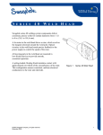
www.swagelok.com
S
E R I E S
8HPH W
E L D
HEAD
USER’S MANUAL
Unpacking the Weld Head Components ............................. 2
Optional Mounting of the Series 8HPH Weld Head............ 3
Installing the Weld Head....................................................... 4
Connecting the Extension Cable to the Weld Head .... 4
Connecting the Weld Head Extension Cable
to the Power Supply ....................................................... 5
Electrode Selection and Installation..................................... 7
Inspecting the Electrode ................................................ 7
Calculating Electrode Length ........................................ 7
Installing or Replacing the Electrode ............................ 9
Operation .............................................................................12
Preparing the Work ......................................................12
Fixturing the Work Pieces............................................13
Performing a Weld........................................................16
Changing the Side Plates ............................................18
Performing Daily Maintenance ...........................................23
Daily Fixture Maintenance ...........................................23
Daily Weld Head Maintenance ....................................23
Performing Periodic Maintenance......................................24
Series 8HPH Cleaning and Inspection .......................24
Ceramic Insert Replacement .......................................33
Arc Shield Replacement ..............................................34
Work Support System .........................................................35
Right/Left Work Support Instructions ..........................35
Parts Drawings ....................................................................37
Series 8HPH Weld Head
M W
SWEERL DI IENSG S8 YHS TPEH
C
E L D
Swagelok® series 8HPH (high performance) weld heads
deliver consistent, precise welds for outside diameters from
1/8 to 1/2 in. and 3 to 12 mm. Designed for the rigors of the
production environment and for cleanroom compliance, the
series 8HPH is encased in a metal shroud. It is capable of
performing up to four times as many welds as the
traditional micro weld head in the same amount of time.
The series 8HPH also provides the benefit of enhanced
operator comfort, as the actuator handles allow the operator
to fixture work pieces without touching the fixture plates.
A dc motor in the weld head drives a rotor, which revolves
the tungsten electrode around the weld joint. Optical
circuitry in the weld head sends precise feedback to the
power supply to control the speed of the rotor. The
electrode is positioned in the eight o’clock position
to facilitate visual joint alignment.
H
E A D
Open
1.Not Locked/Closed
Tool
Change
Locked
Figure 1 Series 8HPH Weld Head
A spring-loaded, floating brush maintains contact with
approximately two-thirds of the circumference of the
rotor. This configuration ensures consistent, uniform
electrical conductance to the rotor and electrode.
This manual presents information that is specific to the
high performance weld head. The weld head fixtures do
not use separate collets but rather have separate side
plates with integral collet features.
Formal training on the operation, fixture plate
installation, and maintenance is recommended.
© 2004, 2005, 2006 Swagelok Company, all rights reserved
May 2006
1
Series 8HPH Weld Head
Unpacking the Weld Head
Components
The following weld head components are packaged in a
foam-lined shipping container:
•
weld head
•
electrode package
•
centering gauge
•
series 8HPH tool package
•
extension cable
•
user’s manual
The series 8HPH weld head has size-specific side plates,
and the order number specifies which set will be installed
upon receipt. Other side plate sizes are optional
accessories. The side plate size ordered will determine the
electrode package that is delivered with the weld head.
Figure 2
Shipping Container
Perform the following steps when your Swagelok series
8HPH weld head arrives.
1. Inspect the container for damage.
2. Remove the components from the container.
3. Check the items for any damage.
4. Verify that the weld head serial number matches the
serial number on the shipping container.
5. Record the model and serial numbers and the
delivery date on the Warranty Information form.
2
© 2004, 2005, 2006 Swagelok Company, all rights reserved
May 2006
Series 8HPH Weld Head
Optional Mounting of the
Series 8HPH Weld Head
The series 8HPH weld head comes with predrilled holes for
optional bench-top mounting.
1. Determine the mounting orientation of the weld
head on the workbench.
4 in.
(102 mm)
9/32 in. dia.
(7 mm)
2. Use the integral mounting holes on the bottom of
the unit to secure the unit to the workbench.
3. Drill holes in workbench using the dimension
guide in Figure 3.
Caution!
Do not drill into the weld
head. The mounting holes
on the unit are a specific
depth to prevent damage to
internal parts.
4 in.
(102 mm)
Figure 3 Series 8HPH Mounting
Dimension Guide
4. Align holes on bottom of weld head unit to holes
in workbench.
5. Insert four 1/4 in. × 20 machine screws of
appropriate length (not included) through the
workbench into the weld head unit. See Figure 4.
Figure 4 Optional Mounting of the Weld
Head to the Bench
© 2004, 2005, 2006 Swagelok Company, all rights reserved
May 2006
3
Series 8HPH Weld Head
Installing the Weld Head
Connecting the Extension Cable to the
Weld Head
The four connectors on the cable are:
4
1 threaded multi-pin connector
3
2
2 electrode (red)
1
3 work (green)
4 weld head shielding gas
Figure 5 Connecting the Weld Head to
the Extension Cable
1. Align the notch on the threaded multi-pin connector
of the weld head cable with the small tab in the
mating socket of the extension cable. Insert the
threaded connector and screw on the weld head
cable by turning clockwise until it is tight.
2. Align the arrow on the female socket of the weld
head electrode cable (red) with the arrow on the
male connector (red) of the extension cable. With
the arrows aligned, insert and fully seat the red male
connector of the extension cable into the red female
socket of the weld head cable. Twist the connector
one-quarter turn clockwise to lock into place.
3. Align the arrow on the male connector of the weld
head work cable (green) with the arrow on the
female socket (green) of the extension cable. With
the arrows aligned, insert and fully seat the green
male connector of the weld head cable into the
green female socket of the extension cable. Twist
the connector one-quarter turn clockwise to lock
into place.
4. Insert the male shielding gas connector of the weld
head cable into the female Swagelok quick-connect
body of the extension cable. Align bodies and stems
when coupling or uncoupling.
4
Figure 6
Connecting the Weld Head to
the Extension Cable
Caution!
Do not rotate quick-connects
while coupled. Do not insert
foreign object into uncoupled
bodies or stems.
© 2004, 2005, 2006 Swagelok Company, all rights reserved
May 2006
Series 8HPH Weld Head
Connecting the Weld Head Extension
Cable to the Power Supply
The weld head extension cable has four connectors that
plug into the power supply. See Figure 7.
1. Attach the threaded multi-pin connector of the
extension cable to the mating socket on the rear
panel of the power supply labeled FIXTURE. Turn
the connector sleeve clockwise by hand until it is
tight. This connection provides the control signals
to drive the weld head.
Caution!
Ensure that the threaded
multi-pin connector is
fully seated in the mating
socket and the threaded
sleeve is tight.
2
1
3
4
Figure 7 Connecting the Weld Head
Extension Cable to the Power
Supply
2. Insert and fully seat the red connector of the
extension cable into the socket on the rear panel of
the power supply labeled ELECTRODE. Twist the
connector one-quarter turn clockwise to lock into
place. This connection is the negative (-) terminal
of the weld head.
3. Insert and fully seat the green connector of the
extension cable into the socket on the rear panel of
the power supply labeled WORK. Twist the
connector one-quarter turn clockwise to lock into
place. This connection is the positive (+) terminal
of the weld head.
4. Insert the shielding gas connector stem into
the Swagelok quick-connect body labeled
TO WELD HEAD.
Figure 8 Turning the Power
Supply ON
Caution!
Ensure the connector is
firmly attached. This
connection provides
shielding gas to the weld
head through a solenoid
valve in the power supply.
5. Turn the power ON. See Figure 8.
© 2004, 2005, 2006 Swagelok Company, all rights reserved
May 2006
5
Series 8HPH Weld Head
6. Press HOME to return the rotor to the home
position. See Figure 9.
7. Check that the rotor returns to the appropriate home
positions. See Figure 10.
Caution!
The weld head should not be
started in any rotor position
except home. Arc start in any
other location may cause
weld head damage.
8. If the rotor does not return to the home position,
see the Fixture Disassembly procedure in
Performing Periodic Maintenance.
Figure 9
Power Supply
Operator Panel
Incorrect
Correct
Figure 10 Home Position of Rotor
6
© 2004, 2005, 2006 Swagelok Company, all rights reserved
May 2006
Series 8HPH Weld Head
Electrode Selection
and Installation
Inspecting the Electrode
This illustration shows the electrode shape Swagelok
recommends. Properly ground electrodes provide
consistent, repeatable welds. Pre-ground electrodes
are available from your Swagelok sales and service
representative. See Table 1 and Table 2 for
ordering information. Tip diameters listed in the tables
are for argon only. Other shielding gases may require
different tip diameters.
The electrode ordering numbers are assigned as follows:
SWS –
X.040
-
Electrode
Diameter (in.)
Material Designator
C = Ceriated
T = Thoriated
#.###
Electrode
Length (in.)
-
.###
Figure 11 Tungsten Electrode
P
Piece
Tip
Diameter (in.) Designator
Caution!
Only ceriated tungsten
should be used in the weld
head. The use of other types
of tungsten may cause weld
head damage.
The ceriated electrode material type is a mixture of
98 % tungsten and 2 % cerium and is commonly referred to
as “2 % ceriated.” This electrode type has demonstrated
improved arc starting performance over the 2 % thoriated
type, particularly when using purified shielding gas.
Calculating Electrode Length
Electrode length depends on the desired arc gap and
outside diameter of the work piece being welded. The
series 8HPH comes with electrodes machined to specific
arc gaps. Certain electrodes will automatically be selected
for inclusion with the series 8HPH when it is ordered,
based on the diameter of the tubing being welded.
Electrode Length = 0.615 - [(Component OD) / 2] - Arc Gap
Example: For a 0.500 in. component with a 0.035 in.
arc gap: 0.615 - (0.500/2) – 0.035 = 0.330 in.
This value is inserted into the Swagelok electrode ordering
number as follows: SWS-C.040-.330-.###-P
See your authorized Swagelok sales and service
representative if custom arc gaps or tip diameters are
desired, which are not listed in Table 1 or Table 2.
© 2004, 2005, 2006 Swagelok Company, all rights reserved
May 2006
7
Series 8HPH Weld Head
Table 1 Series 8HPH Electrode Selection (Fractional)
Component OD
Arc Gap
(in.)
(in.)
1/8
1/4
3/8
1/2
0.020
0.025
0.030
0.035
0.025
0.030
0.035
0.040
0.025
0.030
0.035
0.040
0.030
0.035
0.040
0.045
Electrode
Length (in.)
0.533
0.528
0.523
0.518
0.465
0.460
0.455
0.450
0.403
0.398
0.393
0.388
0.335
0.330
0.325
0.320
Electrode Ordering
Number
SWS-C.040-.533-.012-P
SWS-C.040-.528-.012-P
SWS-C.040-.523-.012-P
SWS-C.040-.518-.012-P
SWS-C.040-.465-.012-P
SWS-C.040-.460-.012-P
SWS-C.040-.455-.012-P
SWS-C.040-.450-.012-P
SWS-C.040-.403-.012-P
SWS-C.040-.398-.012-P
SWS-C.040-.393-.012-P
SWS-C.040-.388-.012-P
SWS-C.040-.335-.012-P
SWS-C.040-.330-.012-P
SWS-C.040-.325-.012-P
SWS-C.040-.320-.012-P
Note: The electrodes listed in
Table 1 and Table 2 are for
argon shielding gas only.
Table 2 Series 8HPH Electrode Selection (Metric)
Component OD
Arc Gap
(mm)
(mm)
3
6
8
10
12
8
0.51
0.64
0.76
0.89
0.64
0.76
0.89
1.02
0.64
0.76
0.89
1.02
0.76
0.89
1.02
1.14
0.76
0.89
1.02
1.14
Electrode
Length (mm)
13.61
13.49
13.36
13.23
11.99
11.86
11.73
11.61
11.00
10.87
10.74
10.62
9.86
9.73
9.60
9.47
8.86
8.74
8.61
8.48
Electrode Ordering
Number
SWS-C.040-.536-.012-P
SWS-C.040-.531-.012-P
SWS-C.040-.526-.012-P
SWS-C.040-.521-.012-P
SWS-C.040-.472-.012-P
SWS-C.040-.467-.012-P
SWS-C.040-.462-.012-P
SWS-C.040-.457-.012-P
SWS-C.040-.433-.012-P
SWS-C.040-.428-.012-P
SWS-C.040-.423-.012-P
SWS-C.040-.418-.012-P
SWS-C.040-.388-.012-P
SWS-C.040-.383-.012-P
SWS-C.040-.378-.012-P
SWS-C.040-.373-.012-P
SWS-C.040-.349-.012-P
SWS-C.040-.344-.012-P
SWS-C.040-.339-.012-P
SWS-C.040-.334-.012-P
© 2004, 2005, 2006 Swagelok Company, all rights reserved
May 2006
Series 8HPH Weld Head
Installing or Replacing the Electrode
The series 8HPH weld head tool package includes:
•
a miniature hex drive
•
wire brushes
•
tweezers
•
a hex wrench set.
Caution!
Do not press JOG or move
the rotor unless the electrode
is clamped in place.
Use these tools for installing a new size of electrode, or for
replacing the electrode when it shows signs of deterioration.
Reducing the jog speed may be helpful for correct
positioning of the rotor.
1. To reduce jog speed, press SETUP on the
operator panel.
2. Select CONFIG from the setup options.
3. Select a jog speed of 50 % or less.
4. Open the side plates by pushing each actuator handle
back to the open position. See Figure 13.
Figure 12 Pressing SETUP on the
Operator Panel
Figure 13 Pushing Actuator Handles
to the Open Position
© 2004, 2005, 2006 Swagelok Company, all rights reserved
May 2006
9
Series 8HPH Weld Head
5. With the weld head in the open position, press JOG on
the operator panel (see Figure 14) until the tungsten
electrode is in the position shown in Figure 15.
Figure 14 Pressing JOG on the
Operator Panel
Electrode
Figure 15 Jogging the Rotor until the
Electrode is Accessible
10
© 2004, 2005, 2006 Swagelok Company, all rights reserved
May 2006
Series 8HPH Weld Head
6. Loosen the electrode set screw with the hex drive.
See Figure 16.
Caution!
Hold on to the electrode with
tweezers so that the
electrode does not fall into
the weld head gear assembly.
7. Remove and discard the old electrode.
8. Install a new electrode using the tweezers. Insert the
electrode through the ceramic insulator and into the
rotor to its full insertion depth. Make sure the sharp
tip of the electrode is pointing out. See Figure 16.
9.
Tighten the set screw sufficiently to prevent the
electrode from falling out of the rotor.
Caution!
Do not overtighten the set
screw, as it could damage
the electrode, screw, or
rotor threads.
Figure 16 Loosening the Electrode
Set Screw
Note: Replace the electrode set screw if
any sign of stripping is observed.
10. Press HOME to return the rotor to the home position
as shown in Figure 17.
Incorrect
Correct
Figure 17 Home Position of Rotor
© 2004, 2005, 2006 Swagelok Company, all rights reserved
May 2006
11
Series 8HPH Weld Head
Operation
Preparing the Work
It is important to prepare the components properly before
welding. See Figure 18. Components must be square and
burr-free to ensure repeatable, high-quality autogenous
fusion welds.
Follow these steps to achieve square and burr-free tubing:
1. Cut the tubing to length with a hacksaw or tube cutter.
2. Face the tube ends with a lathe or a portable facing
tool.
3. Deburr the ends, making sure that both the inside and
outside diameters are square and burr-free.
4. Clean the tube ends using an appropriate solvent.
Minimize the chance of a poor quality weld by following
these guidelines:
•
Tube ends must be square.
•
Tube ends must not have a wall thickness
variation exceeding ± 15 % of nominal.
•
Tube ends must be burr-free.
•
Tube ends must be free of any rust, grease, oil,
paint, or other surface contaminants.
Method
Result
Burrs in
Flow Path
Burrs
Hacksaw Cut
Gap
End Rolled by Cutter
Blade and Roller
Irregular Tube
Diameter
Tube Cutter
Burrs
Face Perpendicular
to Axis
Reduced Flow Area
Smooth Transition at
Wall Faces
Tube Facing Tool
Square Corners
No Gaps
Figure 18 Preparing the Tube
12
© 2004, 2005, 2006 Swagelok Company, all rights reserved
May 2006
Series 8HPH Weld Head
Fixturing the Work Pieces
It is very important that the work pieces are aligned so that
the electrode is in the seam of the joint, and that the ends are
butted squarely. If the work pieces are out of alignment, you
may experience angular or axial misalignment weld defects.
See Figure 19 and Figure 20.
Figure 19
Angular Misalignment
Figure 20
Axial Misalignment
Visual Alignment
To secure a work piece into the fixture, the user actuates
the right movable clamp with the left handle. The left
movable clamp is actuated in a similar fashion. See
Figure 21. This method of operation allows the user to
operate the fixture with one hand while holding and aligning
the work piece with the other.
Left Handle
Right Handle
Electrode
1. Insert the first work piece into either side of the
fixture and visually align the end of the work piece
with the electrode tip.
Tube
2. Clamp the work piece by placing the handle in the
not locked/closed position.
3. Insert the other work piece and butt it up to the
clamped work piece. Clamp the second work piece.
4.
Place both handles in the locked/closed position.
© 2004, 2005, 2006 Swagelok Company, all rights reserved
May 2006
Movable Side Plate
Figure 21
Aligning the Electrode with
the Tube End and Clamping
the First Work Piece
13
Series 8HPH Weld Head
Alignment Using the Centering Gauge
The centering gauge is supplied attached to the weld head
and must be adjusted before use. The following steps refer
to the left movable clamp.
Note: The centering gauge can be set for use with either
the left or right movable clamp.
Note: In order to use the centering gauge in the right
movable clamp, the gauge must first be adjusted to work
with the right movable clamp. The centering gauge
adjustment procedure is the same for both the left and right
movable clamps.
Locking
Screw
Figure 22 Loosening the Locking Screw
1. Loosen the locking screw, using the supplied hex
key. See Figure 22.
2. Clamp the centering gauge around the circular
surface shown in Figure 23, using the left
movable clamp. See Figure 24.
Surface to
be Clamped
Figure 23 Surface to be Clamped
Figure 24 Centering Gauge Clamped
into Position
14
© 2004, 2005, 2006 Swagelok Company, all rights reserved
May 2006
Series 8HPH Weld Head
3. Ensure that the centering gauge is pushed against the
side plate.
4. Adjust the centering gauge so that the right edge is
centered on the electrode. See Figure 25.
5. Tighten the centering gauge locking screw.
Electrode
Locking Screw
Right Edge of
Centering Gauge
Figure 25
Adjusting the
Centering Gauge
6. Insert the work piece into the other side of the
fixture and butt it squarely against the end of the
centering gauge. See Figure 26.
Work Piece
Locking Screw
Centering Gauge
Figure 26
Inserting the Work Piece
Figure 27
Clamping the Work Piece
7. Clamp the work piece into place. See Figure 27.
8. Remove the centering gauge and insert the other
work piece to be welded, butting it up against the
first work piece. Clamp the second work piece
in place.
Note: At the start of every shift, or whenever the electrode
is changed, ensure the centering gauge is re-centered.
© 2004, 2005, 2006 Swagelok Company, all rights reserved
May 2006
15
Series 8HPH Weld Head
Performing a Weld
Operate the weld head using the following parameters:
Series 8HPH
3
①
Shield gas flow rate std ft /hr
(std L/min)
10 to 15①
(4.7 to 7.1)
Prepurge and Postpurge
minimum time in seconds
Continuous
Start Power
U-low, Low, Norm②
Maximum Recommended
Average Amps
40 Amps
Caution!
Do not use tack programs
or programs that include
tacks with the series 8HPH
weld head.
Caution!
Do not use step programs
with the series 8HPH
weld head.
Set flow to higher rates when welding at high current rates.
②
M100-1 Power Supplies with serial numbers before 2802; D100-1 Power Supplies with
serial numbers before 1425; D100-2 Power Supplies with serial numbers before 3267; or
M100-2 Power Supplies with serial numbers before 3464 and ac arc start should use Low
or U-low arc starts. All D-100-1A and D-75 units should use Low or U-low arc starts.
Power supplies with dc arc starts should use Normal for wall thickness above 0.030 in.
16
© 2004, 2005, 2006 Swagelok Company, all rights reserved
May 2006
Series 8HPH Weld Head
Verify the Alignment of the Work
The series 8HPH weld head allows the user to verify work
piece alignment while fixtured. To check the weld joint
BEFORE initiating the weld sequence:
1. Open the arc shield by pushing down on the thumb
tab. See Figure 28.
2. Release the tab to have the arc shield return to the
closed position.
Caution!
Provide support to the
purge tube and heavy work
pieces to prevent an
unacceptable weld, damage
to the series 8HPH weld
head, or both.
3. Program the power supply as instructed in the power
supply manual.
4. Press PURGE to begin shielding gas flow. The
shielding gas should remain on at all times when
using the weld head.
5. Check the shielding gas flow rate. Proper shielding
gas flow for this weld head is 10 to 15 std ft3/hr
(4.7 to 7.1 std L/min).
Figure 28
Arc Shield Open
Figure 29
Arc Shield Closed
6. Verify the arc shield is in the closed position.
See Figure 29.
WARNING!
CLOSE ARC SHIELD
BEFORE BEGINNING WELD.
USER COULD BE EXPOSED
TO THE UV RAYS OF THE
ARC IF THE ARC SHIELD IS
NOT CLOSED DURING
WELDING.
Caution!
Quality of the weld could
be affected by an open
arc shield during welding.
© 2004, 2005, 2006 Swagelok Company, all rights reserved
May 2006
17
Series 8HPH Weld Head
Changing the Side Plates
Side Plate Removal
1. Unhook the arc shield return spring that is holding
the arc shield assembly in place. See Figure 30.
Tool
Change
Lever
Arc Shield
Arc Shield
Return Spring
Figure 30 Removing the Arc Shield
Return Spring from the
Movable Plate Assembly
2. Push and hold the tool change lever back while
pushing each handle to its rear-most position. Once
each handle is back, release the tool change lever to
lock the handles in the tool change position. See
Figure 31.
Actuator
Handles
Back
Figure 31 Positioning the Weld Head
for a Tool Change
18
© 2004, 2005, 2006 Swagelok Company, all rights reserved
May 2006
Series 8HPH Weld Head
3. Remove the cap screw and washer. See Figure 32.
Washer
Cap
Screw
Figure 32
Removing the Cap Screw
and Washer
4. Remove outer movable side plate, arc shield
assembly, adapter hub, thrust bearing, and inner
movable side plate. See Figure 33.
5.
Set aside the inner and outer movable side plates.
Keep the thrust bearing, adapter hub, and arc shield
assembly nearby for reinstallation.
Inner Movable
Side Plate
Adapter Hub
Thrust Bearing
Arc Shield Assembly
Outer Movable Side Plate
Figure 33
Removing the Movable Side
Plate Assembly
6. Release the side plate latch.
7. Remove the two shoulder screws from the fixed
side plate.
Fixed
Side
Plate
8. Pull the fixed side plate off of the fixture.
See Figure 34.
Figure 34
© 2004, 2005, 2006 Swagelok Company, all rights reserved
May 2006
Removing the Fixed
Side Plate
19
Series 8HPH Weld Head
Side Plate Installation
1. Select the required side plate size.
2. Slide the fixed side plate over the
weld head.
3. Insert the shoulder screws in the fixed side plate,
but do not tighten.
4. Secure the side plate latch.
5. Secure the fixed side plate with screws. Tighten the
fasteners 1/8 to 1/4 of a turn past finger tight.
See Figure 35.
Figure 35 Installing the Fixed Side
Plate
20
© 2004, 2005, 2006 Swagelok Company, all rights reserved
May 2006
Series 8HPH Weld Head
6. Align the keyed inner plate of the movable side
plate with the notches in the shaft. See Figure 36.
7. Install the inner movable side plate.
8. Reinstall the thrust bearing and adapter hub on
the shaft. Align them with the notched shaft.
See Figure 37.
9. Install the arc shield assembly on hub.
Note: Make sure that the thrust bearing and adapter hub
remain aligned.
10. Install the outer plate of the movable side plate over
the notch of the adapter hub.
© 2004, 2005, 2006 Swagelok Company, all rights reserved
May 2006
Figure 36
Aligning the Keyed Inner
Clamp with the Notched
Shaft
Figure 37
Installing the Movable
Clamp Assembly
21
Series 8HPH Weld Head
11. Reinstall the washer and the screw to secure the
movable clamp assembly. Tighten the fasteners 1/8
to 1/4 of a turn past finger tight.
Figure 38 Reinstalling Washer
and Screw
Note: The movable side plate assembly
should be flush with the weld head when
properly installed.
12. Push and hold the tool change lever back while
pulling each actuator handle to the locked/closed
position. Once each handle is forward, release the
tool change lever.
13. Reattach the arc shield spring.
Figure 39 Locking the Actuator
Handles in the Operation
Position
22
© 2004, 2005, 2006 Swagelok Company, all rights reserved
May 2006
Series 8HPH Weld Head
Performing Daily Maintenance
To keep your Swagelok welding system equipment in
proper working order, you must perform daily maintenance
on the system components.
Daily Fixture Maintenance
At the beginning of each workday:
Caution!
Do not use lubricants inside
the weld head.
Clean the Inside
Surfaces of the
Movable
Side Plates
Clean the
Arc Shield
1. Place the handles in the tool change position.
2. Use a stainless steel wire brush to clean the collet
surfaces of the side plates that contact the work.
See Figure 40.
3. Remove dirt, carbon and vapor deposits from the
arc shield and movable side plates with a swab and
isopropyl alcohol.
Clean Fixed
Side Plates
Figure 40
Inspecting Side Plates and
Arc Shield
Daily Weld Head Maintenance
1. Remove dirt, carbon, and vapor deposits from the
weld head rotor area with a clean, soft cloth or swab
and a 90 % or greater isopropyl alcohol solvent.
Clean Both Sides of
the Rotor
2. Clean the exposed areas of the ceramic insert with
isopropyl alcohol, and inspect for cracks or arcing
damage. If the ceramic insert is damaged, follow the
instructions in Ceramic Insert Replacement to
replace it.
3. Incrementally jog the rotor and clean both sides of
the rotor with a swab and isopropyl alcohol.
See Figure 41.
Store the weld head in a clean, dry place at the end of
each workday.
© 2004, 2005, 2006 Swagelok Company, all rights reserved
May 2006
Figure 41
Jogging and Cleaning Both
Sides of the Rotor
23
Series 8HPH Weld Head
Performing Periodic Maintenance
As the weld head is repeatedly used, parts will begin to
wear. Extensive testing has identified these baseline
maintenance parameters, which can be used to approximate
when certain tasks will need to be done.
This is dependent on the size of work pieces typically being
welded with the machine.
For series 8HPH machines being used primarily to weld
1/4 in. (6.35 mm) or smaller tubing, periodic maintenance
should be conducted every 10 000 welds.
For series 8HPH machines being used primarily to weld
larger than 1/4 in. (6.35 mm) tubing, periodic maintenance
should be conducted every 3 000 welds.
Replace all worn parts. Brush and curved disc springs must
be ordered for periodic maintenance. For detailed part
drawings and ordering information, see the Parts Drawings
at the end of this manual. Spare parts are available through
your authorized Swagelok sales and service representative.
Series 8HPH Cleaning and Inspection
Tool Change Knob
Fixture Disassembly and Cleaning
1. Verify the rotor is in the home position.
Handles
2. Disconnect the unit from the power supply.
3. Loosen the eight screws holding the metal shroud
in place.
4. Push the handles to the not locked/closed position.
5. Remove the tool change knob, by turning it
counterclockwise.
6. Remove the metal shroud by lifting it straight up off
of the base. See Figure 42.
7. Push the handles and tool change lever to the tool
change position.
8. Remove the movable side plates, thrust bearing,
adapter hub, and arc shield assembly.
24
Screws
(Qty. 8)
Figure 42 Removing the Metal Shroud
© 2004, 2005, 2006 Swagelok Company, all rights reserved
May 2006
Series 8HPH Weld Head
9. Remove the fixed side plate screws.
10. Release the fixed side plate latch.
11. Pull the fixed side plate off of the weld head. See
Changing the Side Plates for detailed instructions.
12. Clean the surfaces of fixed side plate and the
movable side plates that contact the work with a
wire brush.
13. Wipe the surfaces of the fixed and movable side
plates with isopropyl alcohol.
14. Remove the two locating shoulder screws and
button head screw to remove the weld head
assembly. See Figure 43.
Screws Securing the
Weld Head to the
Housing
Button Head
Figure 43
Removing the Weld
Head Assembly
15. Disconnect the motor control connector.
16. Unscrew the nut and disconnect the purge gas line.
17. Pull the weld head assembly straight out from the
base to access the power cable. See Figure 44.
Motor Control
(10-pin Connector)
Purge
Gas Line
Power
Cable
Figure 44
© 2004, 2005, 2006 Swagelok Company, all rights reserved
May 2006
Removing the Weld
Head Assembly
25
Series 8HPH Weld Head
18. Disconnect the power cable from the plastic motor
drive housing. See Figure 45.
19. Remove the weld head from the base.
Power
Cable
Figure 45 Disconnecting the
Power Cable
WARNING!
Weld Head Disassembly and Cleaning
A new brush, ceramic insert, and curved disc springs will
need to be ordered prior to performing this procedure. These
items should be replaced during periodic maintenance.
1. Remove the screws securing the side shields of the
weld head.
2. Loosen the two flathead screws at the top of the
brush side cover to remove tension on the side
shield pieces.
DO NOT REPLACE PLASTIC
FLATHEAD SCREWS WITH
METAL FLATHEAD SCREWS.
THIS COULD EXPOSE THE
WELDING OPERATOR TO
WELDING ARC START
VOLTAGES
Loosen to Remove Tension to
Allow Side Shield Removal
3. Lift the bottom of the side shield to unhook it from
the metal insert. See Figure 46.
4. Wipe the surfaces of the side shields and covers with
isopropyl alcohol.
Plastic Screw
Metal Screw
Figure 46 Removing the Side Shields
26
© 2004, 2005, 2006 Swagelok Company, all rights reserved
May 2006
Series 8HPH Weld Head
5. Remove the four plastic flathead screws securing the
brush side cover. See Figure 47.
6. Clean the inside surface of brush side cover with
isopropyl alcohol.
Figure 47
Removing the Brush
Side Cover
Figure 48
Removing the Brush and
Springs
Figure 49
Removing the Rotor
7. Remove the brush, wave spring, and curved disc
springs as shown in Figure 48 and discard. See the
spare parts list in Table 3 for ordering information
and contact your authorized Swagelok sales and
service representative for replacement parts.
8. Remove the rotor. See Figure 49.
© 2004, 2005, 2006 Swagelok Company, all rights reserved
May 2006
27
Series 8HPH Weld Head
9. Clean the teeth of the gears with the nylon brush
included with the weld head. See Figure 50.
10. Clean the gear surfaces with a swab and
isopropyl alcohol. See Figure 50.
11. Clean the track area of the weld head body with a
swab and isopropyl alcohol.
Clean the
Track with
Isopropyl
Alcohol
Figure 50 Cleaning the Guideway of
the Rotor Track with
Isopropyl Alcohol
12. Remove the electrode and ceramic insert and inspect
around the electrode hole for damage.
Note: The ceramic insert is fragile and will crack if not
handled properly.
13. Use a wire brush to eliminate discoloration.
Replace the rotor if arcing damage prevents
normal operation.
14. Clean the rotor with a swab and isopropyl alcohol.
15. Check the ceramic insert for damage. If it is
damaged, replace it according to the Ceramic Insert
Replacement instructions in this manual.
Figure 51 Inspecting the Ceramic
Insert for Damage
28
© 2004, 2005, 2006 Swagelok Company, all rights reserved
May 2006
Series 8HPH Weld Head
Weld Head Reassembly
1. Replace the ceramic insert on the rotor, and secure it
with flathead screws.
2. Install the new electrode, and secure it with a set
screw. See Figure 52.
Note: If you are reassembling following a rotor jam indicated
by the power supply, first reconnect the power supply and
press HOME. Otherwise, after you have reassembled the
weld head, the rotor will “remember” what position it
was in when it jammed, and will not return to its proper home
position. Disconnect the power supply before reassembly.
WARNING!
PINCH POINTS.
KEEP HANDS, LOOSE
CLOTHING AND LONG HAIR
AWAY FROM MOVING
PARTS. SERIOUS INJURY
CAN OCCUR.
Figure 52 Installing the Ceramic
Insert
Caution!
Do not use lubricants inside
the weld head.
3. Reposition the rotor in the drive gear insert of the
weld head. Seat the rotor so that the track fits over the
ridge of the insert. Make sure the rotor is flush with
the ends of the rotor track.
4. Install a new brush, with the three pockets facing
upward. Align the holes of the brush with the screw
holes in the weld head body assembly.
5. Install the new wave spring and two curved disc
springs into the brush pockets, making sure they are
positioned as shown. See Figure 53.
Line up
Holes
Here
Caution!
Be sure that the cover is
lined up correctly or the
springs will shift.
Figure 53 Installing the Brush and
Disc Springs
© 2004, 2005, 2006 Swagelok Company, all rights reserved
May 2006
29
Series 8HPH Weld Head
6. Reinstall the brush side cover.
7. Insert the four plastic flathead screws to secure the
brush side cover. See Figure 54.
WARNING!
DO NOT REPLACE PLASTIC
FLATHEAD SCREWS WITH
METAL FLATHEAD SCREWS.
THIS COULD EXPOSE THE
WELDING OPERATOR TO
WELDING ARC START
VOLTAGES.
Figure 54 Installing the Brush
Side Cover
8. Position the hooked end of the side shield into the
recess at the top of the insert and clamp the side
shield down. See Figure 55.
9. Reinstall the plastic flathead screws and metal
flathead screws to secure the side shields.
WARNING!
DO NOT REPLACE PLASTIC
FLATHEAD SCREWS WITH
METAL FLATHEAD SCREWS.
THIS COULD EXPOSE THE
WELDING OPERATOR TO
WELDING ARC START
VOLTAGES.
30
Plastic Screw
Metal Screw
Figure 55 Installing Side Shields
© 2004, 2005, 2006 Swagelok Company, all rights reserved
May 2006
Series 8HPH Weld Head
10. Reconnect the power cable to the weld head.
11. Slide the weld head into the base and align the
screw holes.
12. Insert the shoulder screws and the button head
screw to secure the weld head in place.
Motor Control
(10-pin Connector)
Purge
Gas Line
Power
Cable
13. Reconnect the motor control connector.
14. Reconnect the purge gas line. See Figure 56.
Figure 56 Reconnect the
Internal Cabling
15. Slide the fixed side plate over the weld
head assembly.
16. Secure the fixed side plate with two shoulder screws.
17. Reinstall the movable side plate assembly. See
Changing the Side Plates for detailed instructions.
18. Move the handles from the tool change to the
not locked/closed position. See Figure 57.
Figure 57 Reinstalling the Side Plates
© 2004, 2005, 2006 Swagelok Company, all rights reserved
May 2006
31
Series 8HPH Weld Head
19. Reinstall the metal shroud straight down.
20. Align the tool change lever with the housing slot
using a screwdriver.
21. Tighten the eight screws that hold the metal shroud
in position. See Figure 58.
Figure 58 Reinstalling the
Metal Shroud
22. Reinstall the tool change knob. See Figure 59.
23. Reconnect the power and turn on the power supply.
Tool Change
Knob
24. Press HOME to verify the rotor rotates smoothly and
stops in home position.
Figure 59 Reinstalling the Tool
Change Knob
32
© 2004, 2005, 2006 Swagelok Company, all rights reserved
May 2006
Series 8HPH Weld Head
Ceramic Insert Replacement
1. Press JOG on the operator panel of the power supply
until the first ceramic flathead screw is exposed.
Remove the first ceramic flathead screw.
Caution!
When removing screws, be
careful not to drop them into
the weld head gear assembly.
2. Press JOG on the operator panel of the power supply
until the second ceramic flathead screw is exposed.
Remove the second ceramic flathead screw.
3. Press JOG on the operator panel of the power supply
until the electrode is at the twelve o’clock position.
4. Remove the electrode set screw. See Figure 60.
5. Remove the electrode.
6. Remove the ceramic insert.
Figure 60 Removing the Electrode
© 2004, 2005, 2006 Swagelok Company, all rights reserved
May 2006
33
Series 8HPH Weld Head
7. Seat the new ceramic insert into the pocket in the
track of the rotor, with the beveled edge facing out.
See Figure 61.
Caution!
Excessive force can break
the ceramic insert.
8. Install a new electrode using the tweezers. Insert the
electrode through the ceramic insulator and into the
rotor to its full insertion depth. Make sure the sharp
tip of the electrode is pointing out of the rotor hole.
9. Tighten the set screw sufficiently to prevent the
electrode from falling out of the rotor.
10. Reinstall the two flathead screws to secure the
ceramic insert.
a. Jog the rotor until you can install one of
the screws.
b. Jog the rotor 300° until you can install the
remaining flat head screw.
Caution!
Make sure that the ceramic
and electrode screws are
snug before operation.
Figure 61 Replacing the Ceramic
Insert
11. Press HOME to return the rotor to the home position.
Arc Shield Replacement
If there is physical damage to the arc shield, it should
be replaced.
1. Remove the four flathead screws securing the arc
shield to the movable clamp. See Figure 62.
Flathead
Screws
2. Remove the old arc shield.
3. Install a new arc shield.
4. Reinstall the four flathead screws.
Figure 62 Replacing the Arc Shield
34
© 2004, 2005, 2006 Swagelok Company, all rights reserved
May 2006
Series 8HPH Weld Head
Work Support System
Note: The work support is sold separately.
Right/Left Work Support Instructions:
1. Attach the 8 in. work support rails to the series 8HPH
weld head unit. See Figure 63.
2. Slide the base onto the rails.
3. Set the base to the desired position and secure with the
knurled thumb screws.
4. Attach and set the right and/or left brace to the
appropriate height on the base. Lock in place using the
knurled thumb screw.
Note: The right or left brace can be used with the V-notch for
tubing or the flat side as needed.
•
For the left work support, use the plastic head
screw for fine adjustments in height and for
additional support as needed.
5. Additional work supports can be attached to the base
of the left or right work supports as needed.
6. An additional work support base can be used as a free
standing work support. Attach the 3.5 in. work support
rail to the top surface of the support base. Secure the
right brace to the appropriate height and angle using
the knurled thumb screw.
© 2004, 2005, 2006 Swagelok Company, all rights reserved
May 2006
35
Series 8HPH Weld Head
4
6
5
3
4
7
1
3
3
5
5
1
2
3
1
4
4
Figure 63 Work Support System
Quantity Per Ordering Number
Ref. No.
Description
Ordering No.
SWS-8HPH-WS
(Full)
SWS-8HPH-WS-LT
(Left)
SWS-8HPH-WS-RT
(Right)
1
2
3
4
5
6
8 in. Work Support Rail
3.5 in. Work Support Rail
10-32 Knurled Thumb Screw
Work Support Slide Base
Work Support Right Brace
Work Support Left Brace
7
Plastic Head Screw
21634
21635
21636
21638
21640
21641
21642-.75
21642-1.00
21642-1.50
4
1
6
2
1
1
1
1
1
2
N/A
3
1
N/A
1
1
1
1
2
1
3
1
1
N/A
N/A
N/A
N/A
36
© 2004, 2005, 2006 Swagelok Company, all rights reserved
May 2006
Series 8HPH Weld Head
Parts Drawings
This section includes exploded assembly drawings and associated parts lists. These drawings are
provided as a guide to identifying part names. For specific part ordering information, contact your
authorized Swagelok sales and service representative.
The parts identified in this section include:
SWS-8HPH Weld Head Assembly
SWS-8HPH Fixture Assembly
© 2004, 2005, 2006 Swagelok Company, all rights reserved
May 2006
37
Series 8HPH Weld Head
Figure 64
38
SWS-8HPH Weld Head Assembly
© 2004, 2005, 2006 Swagelok Company, all rights reserved
May 2006
Series 8HPH Weld Head
Table 3 SWS-8HPH Weld Head Assembly Parts List
Reference No.
1
2
3
4
5
6
7
8
9
10
11
12
13
14
15
16
17
18
19
20
21
22
23
Description
Encoder Circuit Board
Home Sensor Mount Shim
Home Sensor
Home Sensor Mount
SS Socket Head Cap Screw, 2-56 x 0.375 in.
SS Socket Head Cap Screw, 2-56 x 0.187 in.
Weld Head Body Assembly
Cover, Motor Side
Motor Mount
Cover, Brush Side
Rotor
Ceramic Insert
Motor Mount Side Cover
Side Shield
Purge Bayonet
SS Socket Head Cap Screw, 4-40 x 0.250 in.
Quick-connect Tab
Insulating Drive Gear
Drive Gear Retaining Washer
Plastic Flathead Screw, 2-56 x 0.219 in.
S.S. Flathead Screw, 4-40 x 0.250 in.
SS Electrode Set Screw, 3-48 x 0.063 in.
Electrode
24
25
26
27
28
29
30
31
32
33
34
35
36
Brush
SS Shoulder Screw 4-40 x 0.375 in.
Curved Disc Spring
SS Socket Head Cap Screw, 6-32 x 0.250 in.
SS Flathead Screw, 1-64 x 1.25 in.
Encoder Wheel
Motor
Drive Coupler Pin
Drive Coupler Pin Sleeve
Sleeve Sensor Mount
Drive Coupler
SS Dowel Pin, 0.093 x 0.125 in.
Wave Spring
© 2004, 2005, 2006 Swagelok Company, all rights reserved
May 2006
Ordering No.
N/A
N/A
N/A
N/A
N/A
N/A
21511
21502
N/A
21501
21513
21514
N/A
21503
N/A
13112
21520
N/A
N/A
21518
21517
21522
See 0
and 0
21507
21519
21508
N/A
21528
N/A
N/A
N/A
N/A
N/A
N/A
N/A
21530
Minimum Order Qty.
N/A
N/A
N/A
N/A
N/A
N/A
1
1
N/A
1
1
1
N/A
1
N/A
10
1
N/A
N/A
10
10
10
10
1
10
10
N/A
10
N/A
N/A
N/A
N/A
N/A
N/A
N/A
1
39
Series 8HPH Weld Head
Figure 65 SWS-8HPH Housing
40
© 2004, 2005, 2006 Swagelok Company, all rights reserved
May 2006
Series 8HPH Weld Head
Table 4 SWS-8HPH Housing
Reference No.
1
2
3
4
5
6
7
8
9
10
11
12
13
14
15
16
17
18
19
20
21
22
23
24
25
26
27
28
29
30
31
32
33
34
35
36
Description
Top Platform
Outer Support Plate
1/8 in. Fixed Side Plate
1/4 in. Fixed Side Plate
3/8 in. Fixed Side Plate
1/2 in. Fixed Side Plate
3 mm Fixed Side Plate
6 mm Fixed Side Plate
8 mm Fixed Side Plate
10 mm Fixed Side Plate
12 mm Fixed Side Plate
Clamp Stop Assembly
Clamp Block
Adapter Hub
1.25 in. OD ; 0.56 in. ID Bronze Washer
1.25 in. OD ; 0.75 in. ID Bronze Washer
10-32 ; 0.500 in. Socket-head Cap Screw
10-32 ; 0.69 in. dia Black Knob
5/16-18 3/8 ; 2.5 in. LG Socket-head Shoulder Screw
0.750 in. OD ; 0.375 in. ID Thrust Washer
Left Handle Assembly
Right Handle Assembly
Nylon Washer, 3/16 in. dia
Left Spring Link
Right Spring Link
Spring Eyelet
1/4-20 Hex Nut
E-clip
Strut
Actuator Extension Spring
8-32 3/16 x 1/4 in. LG Socket-head Shoulder Screw
Wave Coil Spring
Clamp Stop Extension Spring
Fixture Feet
8-32 5/8 x 3/16 in. LG Socket-head Shoulder Screw
Actuator Assembly Outer Clamp
Actuator Assembly Inner Clamp
Needle Roller Thrust Bearing
1.000 in. OD 10 Fender Washer
10-32 x 3/8 in. Button-head Cap Screw
Metal Shroud
Arc Shield Hub
Arc Shield
Arc Shield Return Spring
© 2004, 2005, 2006 Swagelok Company, all rights reserved
May 2006
Ordering No.
N/A
N/A
21539-02
21539-04
21539-06
21539-08
21539-3MM
21539-6MM
21539-8MM
21539-10MM
21539-12MM
N/A
N/A
21560
N/A
N/A
N/A
21568
N/A
N/A
N/A
N/A
N/A
N/A
N/A
N/A
N/A
N/A
N/A
N/A
21581
N/A
N/A
21577
N/A
N/A
N/A
21591
21593
21592
21588
21596
21594
21580
Minimum Order Qty.
N/A
N/A
1
1
1
1
1
1
1
1
1
N/A
N/A
1
N/A
N/A
N/A
1
N/A
N/A
N/A
N/A
N/A
N/A
N/A
N/A
N/A
N/A
N/A
N/A
10
N/A
N/A
10
N/A
N/A
N/A
1
1
10
1
1
1
1
41
Series 8HPH Weld Head
Reference No.
37
38
39
40
41
42
43
44
45
46
47
48
49
50
51
52
(Not Shown)
42
Description
1/8 in. Movable Side Plate
1/4 in. Movable Side Plate
3/8 in. Movable Side Plate
1/2 in. Movable Side Plate
3 mm Movable Side Plate
6 mm Movable Side Plate
8 mm Movable Side Plate
10 mm Movable Side Plate
12 mm Movable Side Plate
Motor Wire Harness
Strain Relief Assembly
Handle Cover
S.S Button Head Screws, 1/4-20 x 2.00 in.
Flathead S.S. 2-56 x 0.188 in. Screws
Backing Plate
Cable-tie Mount
Spring Link Pin
10-24 1/4 x 3/4 in. LG Socket Head Shoulder Screw
S.S. Button Head Screws, 8/32 x 1.00 in.
S.S. Flathead Screw, 4-40 x 0.250 in.
Latch Catch
4-40 Star Lock Nut
Latch
1/8 in. Centering Gauge
1/4 in. Centering Gauge
3/8 in. Centering Gauge
1/2 in. Centering Gauge
3 mm Centering Gauge
6mm Centering Gauge
8 mm Centering Gauge
10 mm Centering Gauge
12 mm Centering Gauge
Ordering No.
21543-02
21543-04
21543-06
21543-08
21543-3MM
21543-6MM
21543-8MM
21543-10MM
21543-12MM
N/A
N/A
21601
N/A
21606
N/A
N/A
N/A
21626
21607
21517
21643
13103
11520
SWS-8HPCG-02
SWS-8HPCG-04
SWS-8HPCG-06
SWS-8HPCG-08
SWS-8HPCG-3MM
SWS-8HPCG-6MM
SWS-8HPCG-8MM
SWS-8HPCG-10MM
SWS-8HPCG-12MM
Minimum Order Qty.
1
1
1
1
1
1
1
1
1
N/A
N/A
10
N/A
10
N/A
N/A
N/A
10
10
10
1
1
1
1
1
1
1
1
1
1
1
1
© 2004, 2005, 2006 Swagelok Company, all rights reserved
May 2006
Warranty Information
Swagelok products are backed by The Swagelok Limited
Lifetime Warranty. For a copy, visit swagelok.com or contact
your authorized Swagelok representative.
Swagelok—TM Swagelok Company
© 2004, 2005, 2006 Swagelok Company
Printed in U.S.A., OM
May 2006, R2
MS-13-170