1
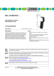
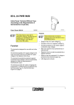
IBS RL 24 DIO 8/8/8-R-LK(-2MBD) Digital Input/Output Module With Eight Inputs and Eight Outputs That Can Be Read Data Sheet 636901 Product Description Note IBS RL 24 DIO 8/8/8-R-LK (500 kbaud) – IBS RL 24 DIO 8/8/8-R-LK-2MBD (2 Mbaud) po – om A mixed operation of modules with different transmission rates is not permitted. in ec – INTERBUS protocol (EN 50254) IP67 protection – Optical fiber bus connection – QUICKON connectors for connecting the supply voltage – Sensors and actuators are connected using 5-pos. M12 female connectors on l – – Installation options: directly to the welding robot on aluminum profiles two-position attachment direct mounting 636901 co s. ne The module is available in two different versions with different transmission rates: This data sheet is only valid in association with the "Configuring and Installing the Rugged Line Product Range" User Manual IBS RL SYS PRO UM E. nt The module is designed for use in systems engineering. With IP67 protection, it is suitable for use without a control cabinet in harsh industrial conditions. It can, for example, be used on the tool platform, directly on welding robots or in conveying systems. Features m 05/2003 Please note that the bus connectors and the mounting plate are not supplied as standard (see ordering data on page 19). Only connect and remove the bus connectors with the power switched off (connection according to DIN EN 60204-1:1993-06). To ensure IP67 protection you must note the following points: – The bus connectors must be connected. – You must not pierce the grommet of unused bus connectors. (For example, some connectors are not used if the module is the last device in the bus.) – Cover unused M12 female connectors with protective caps. Only power supply units with safe isolation should be used. 1 IBS RL 24 DIO 8/8/8-R-LK(-2MBD) Connector Pin Assignment m 1 s. co 2 Connector pin assignment of the INTERBUS remote bus and the power supply INTERBUS remote bus (optical fiber) 2 US1/US2 power supply US1 = bus/sensor supply US2 = actuator supply For additional information about the connector pin assignment and assembly, please refer to the IBS RL SYS PRO UM E User Manual. Signal Direction Splice Ring Wire Color Incoming bus Optical fiber Remote IN Receive data IN Orange Send data OUT Black Outgoing bus Optical fiber Remote OUT Receive data IN Black Send data OUT Orange on l 1 The contact rating for all US1 and US2 contacts is 16 A each. Bus Connector in ec Pos. in Figure 1 om INTERBUS remote bus po 1 ne Figure 1 nt 5 9 1 8 0 0 7 US1/US2 power supply Pos. in Figure 1 2 2 Signal Connection Wire Color Designation +24 V US1 1 Black 1 GND US1 2 Black 2 +24 V US2 3 Black 3 GND US2 4 Black 4 Functional earth ground 5 Yellow 5 636901 IBS RL 24 DIO 8/8/8-R-LK(-2MBD) Connection of Inputs and Outputs Two inputs are assigned to each of the female connectors 0 to 3; two outputs are assigned to female connectors 4 to 7. 1 m 2 5 3 4 5 6 nt 3 7 Pin assignment of 5-pos. M12 female connectors (1) Female Connector 0 1 Female Connector 1 po Pin 2 Female Connector 2 om Figure 2 1 ne 0 s. co 4 Female Connector 3 Female Connector 4 US1-1 V (sensor supply) 2 IN1 IN5 4 IN0 IN4 Female Connector 6 Female Connector 7 IN7 OUT1 OUT3 OUT5 OUT7 GND US2 IN6 OUT0 OUT2 OUT4 OUT6 Functional earth ground 0 Figure 3 636901 ... ... 3 4 ... ... 7 O U T 6 O U T 7 O U T 0 O U T 1 IN 1 + 2 4 V IN 0 IN 7 + 2 4 V IN 6 on l 5 IN2 Female Connector 5 GND US2 GND US1 in ec 3 IN3 5 5 0 1 A 0 0 5 5 5 0 3 B 0 0 4 Pin assignment of 5-pos. M12 female connectors (2) 3 IBS RL 24 DIO 8/8/8-R-LK(-2MBD) Electrical Isolation + 2 4 V U S 2 S 2 F E + 2 4 V U S 1 m G N D U S 1 co G N D U 5 V nt B u s lo g ic IN IN po om S ta tu s o f O U T 0 to O U T 7 , fe m a le c o n n e c to r 4 to fe m a le c o n n e c to r 7 5 5 0 3 B 0 0 5 on l in ec Figure 4 to u p p ly c to r 0 to c to r 3 O U T O U T ........... S ta tu s o f IN 0 IN 7 , s e n s o r s fe m a le c o n n e fe m a le c o n n e Block diagram F O ne F O s. 2 4 V 4 636901 IBS RL 24 DIO 8/8/8-R-LK(-2MBD) Programming Data ID code 3hex (03dec) Length code 01hex (01dec) Input address area 2 bytes Output address area 2 bytes 2 bytes co Register length m Parameter channel (PCP) Not present Error Messages The bus delivers a short circuit or overload message to the control or computer system, which is stored in the module. – If the output data does match the input data, this is indicated to the control or computer system via the bus and is stored in the module. – The bus indicates to the control or computer system that the supply voltage US1 has dropped below the permissible range. – Upon delivery the module is set up so that errors concerning the supply voltage US1, the sensor supply or the outputs are indicated via the bus. – If the supply voltage US2 is not present or is below the permissible voltage range this is not indicated but only displayed by the US2 LED. In this case, the diagnostics of the outputs is deactivated. Temporarily stored diagnostic information remains stored. The diagnostics function can only be acknowledged once the supply voltage US2 is within the permissible range. The error messages are reset through acknowledgment in the control or computer system. s. – – nt The failure of the sensor supply for a group of four inputs is indicated to the control or computer system via the bus and is stored in the module. – The configuration data and the error messages (except for undervoltage diagnostics) are only stored in the volatile memory of the module. Configuration data and error messages are deleted when the power is reset. on l in ec om po ne – 636901 5 IBS RL 24 DIO 8/8/8-R-LK(-2MBD) INTERBUS Process Data Assignment of the Inputs to the INTERBUS Input Data Word Byte 0 Byte Bit 7 Module Slot 3 Input 7 6 5 4 2 6 5 3 Byte 1 2 1 1 4 3 0 0 2 1 7 6 5 7 0 4 6 3 2 5 15 14 13 12 11 10 0 9 8 1 0 Status output 0 to 7 co Status input 0 to 7 1 4 m (Byte.bit) view Byte 0 Bit 7 Module Slot 7 Output 7 6 5 4 6 6 5 3 2 5 4 3 1 0 7 nt Byte 6 Byte 1 5 4 3 2 4 2 1 ne (Byte.bit) view s. Assignment of the Outputs to the INTERBUS Output Data Word 0 Not used Status output 0 to 7 on l in ec om po For the assignment of the illustrated (byte.bit) view for your control or computer system, please refer to data sheet DB GB IBS SYS ADDRESS, Part No. 90 00 99 0. 6 636901 IBS RL 24 DIO 8/8/8-R-LK(-2MBD) Diagnostic and Status Indicators IB D IA G R C R D F O 1 U S 1 F O 2 R e m o te U S 2 IN T E R B U S Id e n t.: 0 3 M o d u le IN 0 1 0 9 IN 0 8 3 1 4 0 6 0 5 0 4 0 3 0 2 0 1 0 0 IN E 0 7 2 5 6 O U T 7 P O U T 1 0 2 O U T 3 4 O U T 5 6 7 R E 2 3 S S 4 5 6 7 5 5 0 3 B 0 0 2 Positions of the diagnostic and status indicators s. Figure 5 co m 0 O U T 1 1 0 IN E IN 1 Green LED OFF: Flashing at 0.5 Hz: Flashing at 2 Hz: ON: INTERBUS diagnostics Supply voltage not present Supply voltage present, bus not active Supply voltage present, I/O error Supply voltage present, bus active, no I/O error RC Green LED ON: OFF: Remote bus cable check Incoming remote bus connection established Incoming remote bus connection defective or not active RD Yellow LED ON: FO1 Yellow LED om po ne nt IB DIAG Remote bus status (remote bus disabled) Outgoing remote bus switched off in ec Monitoring the incoming optical fiber path Incoming optical fiber path not OK Incoming optical fiber path OK or not used Yellow LED Monitoring the outgoing optical fiber path on l FO2 ON: OFF: ON: OFF: 636901 Outgoing optical fiber path not OK Outgoing optical fiber path OK or not used 7 IBS RL 24 DIO 8/8/8-R-LK(-2MBD) Green LED OFF: Flashing: ON: Monitoring the supply voltage US1 US1 not present US1 below the permissible voltage range US1 present US2 Green LED Flashing: ON: Monitoring the supply voltage US2 US2 below the permissible voltage range/not present US2 present E Red LED ON: Error message Short-circuit of the sensor supply for a group of four inputs. (This error message is stored temporarily on the module. However, the error message is stored in volatile memory and will be lost after a power reset.) IN 0 - 7 Yellow LED ON: OFF: Status per input Input at logic 1 Input at logic 0 co s. nt ne po Permissible mixed optical operation (Outputs at logic 1; buffered error) See also „Error Messages“ on page 5. on l in ec Yellow/red Status per output Output at logic 1 Output at logic 0 Short circuit/overload of an output; OUT process data does not match IN process data. (This error message is stored temporarily on the module. However, the error message is stored in volatile memory and will be lost after a power reset.) om OUT 0 - 7 Yellow/red LED Yellow: OFF: Red: m US1 8 636901 IBS RL 24 DIO 8/8/8-R-LK(-2MBD) I/O error messages Switching Threshold System Message With Deactivated Single-Channel Diagnostics System Message With Activated Single-Channel Diagnostics Indicator on the Device Undervoltage US1 < 16.3 V DC I/O error* Diagnostic parame- US1 LED; ter register 2** current process image Missing voltage/ undervoltage US2 < 16.3 V DC Default: no error; op- Default: no error; US2 LED; tional: diagnostic parame- current I/O error* ter register 2** process image Short circuit/ overload initiator supply > 0.7 A DC I/O error* Short circuit/ overload > 2.6 A DC I/O error* Diagnostic parame- Red LED per output; ter register 2** volatile buffer po ne nt s. Diagnostic parame- Groupter register 2** specific E LED for 4 inputs; volatile buffer om > 10.7 V DC External voltage supply at the output for deactivated output co m Error Message See also „Error Messages“ on page 5 * See also IBS SYS FW G4 UM E in ec ** See also IBS RL SYS PRO UM E System messages Switching Threshold System Message Indicator on the Device Deterioration of optical trans- Optical system remission at the incoming inter- serves reached at face -20.6 dBm, maximum MAU warning FO1; current process image Deterioration of optical trans- Optical system remission at the outgoing inter- serves reached at face -20.6 dBm, maximum MAU warning FO2; current process image on l Error Message 636901 9 IBS RL 24 DIO 8/8/8-R-LK(-2MBD) Housing Dimensions U S 1 U S 2 R e m o te IN T E R B U S Id e n t.: 0 3 M o d u le IN 0 IN 0 8 1 3 0 6 0 5 0 4 0 3 0 2 0 1 0 0 4 IN E 0 7 2 5 6 O U T 7 O U T 1 0 P 2 O U T 3 4 O U T 5 6 7 R E 2 3 S S 4 5 6 7 po Housing dimensions on l in ec om Figure 6 5 5 0 3 B 0 0 3 ne nt s. 1 1 4 m m 0 1 O U T 1 1 0 0 9 IN E IN 1 m F O 2 (4 .4 8 8 ") F O 1 (2 .7 9 5 ") co R D 7 1 m m (2 .6 3 8 ") R C (8 .6 6 1 ") (7 .0 4 7 ") 6 7 m m IB D IA G 2 2 0 m m 1 7 9 m m 10 636901 IBS RL 24 DIO 8/8/8-R-LK(-2MBD) Technical Data General Data Operation: -20°C to +55°C (-4°F to +131°F) Storage/transport: -25°C to +70°C (-13°F to +158°F) Humidity Operation: 100% Storage/transport: 95%, no condensation Air pressure Operation: 860 hPa to 1080 hPa (up to 1500 m [4921 ft.] above sea level) Storage/transport: 660 hPa to 1080 hPa (up to 3500 m [11483 ft.] above sea level) Degree of protection IP67 (DIN 40050, IEC 60529), when installed Seal unused slots/connections to ensure the degree of protection. Class of protection 3 according to VDE 106, IEC 60536 ne nt s. co m Ambient temperature Zinc die-cast, copper and nickel-plated surface po Material Electrical isolation Between bus logic and outputs, test voltage 500 V AC, 50 Hz, 1 min. 220 mm x 114 mm x 71 mm (8.661 in. x 4.488 in. x 2.795 in.) (with bus connectors and mounting plate) Weight Approximately 790 g (without connector and mounting plate) on l in ec om Housing dimensions (width x height x depth) 636901 11 IBS RL 24 DIO 8/8/8-R-LK(-2MBD) Supply Voltage US1 (Bus Logic) 24 V DC Permissible range 18.5 V DC to 32 V DC (ripple included) Ripple 3.6 VPP Nominal current consumption 120 mA, typical, plus supply current for the sensors Surge voltage protection 35 V (0.5 s) Protection against polarity reversal Yes (parallel diode), with external 5 A slow-blow fuse co m Nominal voltage s. Provide the module with an external fuse to protect it against polarity reversal. The power supply unit must be able to supply at least four times the rating of the external fuse. 16 A slow-blow, maximum nt External fuse ne When using the module for the first time in the Rugged Line system protect the supply voltage using a 5 A fuse. If all the modules are correctly connected in the system, the 5 A fuse can be replaced by a 16 A fuse. The system can then be loaded with up to 16 A. om po When working on the supply voltage ensure that the protection against polarity reversal is only present if the Rugged Line system is protected with a 5 A fuse. in ec The voltage US1 is looped through and can be tapped off at the connector for the outgoing remote bus. The maximum continuous current is 16 A. Supply Voltage US1 (Sensor Voltage) The sensors are supplied in groups of four via a short-circuit-proof sensor supply. on l Nominal voltage US1 minus 1 V Current consumption 400 mA total current for all inputs (50 mA per input) Protection Electronic overload/short circuit protection per group (each group comprises 4 inputs) Response time for the short circuit diagnostic message 3 to 5 seconds 12 636901 IBS RL 24 DIO 8/8/8-R-LK(-2MBD) Supply Voltage US2 (Actuator Voltage) 24 V DC Permissible voltage range 18.5 V DC to 32 V DC (ripple included) Ripple 3.6 VPP Nominal current consumption 4 A, maximum Concurrent channel derating None Surge voltage protection 35 V (0.5 s) Protection against polarity reversal Yes (parallel diode), with external 5 A slow-blow fuse co m Nominal voltage s. Provide the module with an external fuse to protect it against polarity reversal. The power supply unit must be able to supply at least four times the rating of the external fuse. 16 A slow-blow, maximum nt External fuse ne When using the module for the first time in the Rugged Line system protect the supply voltage using a 5 A fuse. If all the modules are correctly connected in the system, the 5 A fuse can be replaced by a 16 A fuse. The system can then be loaded with up to 16 A. om po When working on the supply voltage ensure that the protection against polarity reversal is only present if the Rugged Line system is protected with a 5 A fuse. in ec The voltage US1 is looped through and can be tapped off at the connector for the outgoing remote bus. The maximum continuous current is 16 A. INTERBUS Interface Optical fiber (polymer fiber 980 µm/1000 µm) Outgoing remote bus Optical fiber (polymer fiber 980 µm/1000 µm) on l Incoming remote bus Transmission rate IBS RL 24 DIO 8/8/8-R-LK 500 kbaud IBS RL 24 DIO 8/8/8-R-LK-2MBD 2 Mbaud 636901 13 IBS RL 24 DIO 8/8/8-R-LK(-2MBD) Digital Inputs IN0 to IN7 8 Electrical isolation No isolation between I/O devices and bus logic Electrical isolation to the digital outputs, test voltage 500 V AC, 50 Hz, 1 min. Input voltage DIN EN 61131-2 Permissible range 0 signal: -30 V to +5 V Permissible range 1 signal: 11 V to 30 V Input type 1 (DIN EN 61131-2) Input current 3 mA, typical Permissible residual current 0 signal: < 1.0 mA, typical Delay time 0 1 1.5 ms, typical Delay time 1 0 3.5 ms, typical ne nt s. co m Number of inputs Input Voltage (V) 3 6 Typical Input Current (mA) 0 0.31 0.64 1.12 in ec 9 om -30 < UIN < 0.7 po Input Characteristic Curve 1.64 15 2.17 18 2.71 21 3.23 24 3.77 27 4.30 30 4.83 on l 12 Typical Switching Thresholds for Inputs 14 Signal Transition Input Voltage (V) Typical Input Current (mA) 01 8.41 1.0 10 8.41 1.0 636901 IBS RL 24 DIO 8/8/8-R-LK(-2MBD) Digital Outputs OUT0 to OUT7 8 Nominal output voltage UOUT 24 V DC Differential voltage for Inom < 0.1 V Coincidence limitation of outputs None Nominal current Inom 0.5 A Total current 4A Protection Short circuit; overload Nominal load co m Number 48W /12 W Lamp 12 W Inductive 12 VA (1.2 H, 48 W) nt ne Signal delay upon power up of 300 µs, typical - Lamp nominal load - Inductive nominal load - Lamp nominal load in ec - Inductive nominal load om Signal delay upon power down of po - Ohmic nominal load - Ohmic nominal load s. Ohmic 300 µs, typical 300 µs (1.2 H, 48 W), typical 500 µs, typical 500 µs, typical 500 µs (1.2 H, 48 W), typical Switching frequency with - Ohmic nominal load 1 kHz, maximum on l This switching frequency is limited by the selected data rate, the number of bus devices, the bus structure, the software, and the control or computer system used. - Lamp nominal load 1 kHz, maximum This switching frequency is limited by the selected data rate, the number of bus devices, the bus structure, the software, and the control or computer system used. - Inductive nominal load 2 Hz (1.2 H, 12 W), maximum Overload response Auto restart Response time with ohmic overload (12 W, 25°C [77°F]) < 50 ms Inductive overload response Output may be damaged 636901 15 IBS RL 24 DIO 8/8/8-R-LK(-2MBD) Digital Outputs OUT0 to OUT7 Reverse voltage endurance against short pulses Protection up to 3 A DC > -7 V Overcurrent shutdown At 2.6 A, minimum Output current when switched off =0V Output voltage when switched off 500 mV, maximum Output current with ground connection interrupted =0A Switching power with ground connection interrupted =0W Output Current (A) 0.3 0.4 s. 0 0.020 0.035 0.050 0.065 0.080 on l in ec 0.5 om 0.1 0.2 Differential Output Voltage (V) po 0 nt ne Output Characteristic When Switched On (Typical) co Limitation of the demagnetization voltage induced on circuit interruption m Strength against permanently applied surge volt- No age 16 636901 IBS RL 24 DIO 8/8/8-R-LK(-2MBD) Conformance with EMC Directive Conformance With EMC Directive 89/336/EEC Noise Immunity Test According to EN 50082-2 EN 61000-4-2 IEC 61000-4-2 Class 3, Criterion B Electromagnetic fields EN 61000-4-3 IEC 61000-4-3 Criterion A, field strength 10 V/m Fast transients (burst) EN 61000-4-4 IEC 61000-4-4 Class 4, Criterion B Surge voltage EN 61000-4-5 IEC 61000-4-5 Class 2, Criterion B Conducted interference EN 61000-4-6 IEC 61000-4-6 ne nt s. co m Electrostatic discharge (ESD) Criterion A, test voltage 10 V Noise Immunity Test According to NAMUR NE 21 NAMUR NE 21 po Immunity to interference Voltage dips 0 ms to 20 ms, repeat rate 1 s, Criterion 1 EN 55022 Class B, residential on l in ec Noise emission om Noise Emission Test According to EN 50081-2 636901 17 IBS RL 24 DIO 8/8/8-R-LK(-2MBD) Technical Data for the Optical Fiber Interface Optical Power Level PSM-LWLPSM-LWLRUGGED-980/1000 RUGGED-FLEXPSM-LWL980/1000 KDHEAVY-980/1000 Maximum fiber attenuation at 660 nm LED measurement 230 dB/km Typical fiber attenuation at 660 nm LED measurement 200 dB/km 250 dB/km <35 m (114.829 ft.) Minimum transmission distance 1 m (3.281 ft.) 1 m (3.281 ft.) Optical output power at 25°C (77°F) -4.9 dBm, typical Maximum optical output power at 25°C (77°F) ne Optical output power (0°C to 55°C [32°F to 131°F]) nt Transmission distance co <50 m (164.042 ft.) s. a 280 dB/km m Cable type -2 dBm -5.8 dBm, typical -20.6 dBm Optical overrange at 25°C (77°F) > -2 dBm po Minimum optical receiver responsivity (0°C to 55°C [32°F to 131°F]) 14.8 dB Maximum wavelength (0°C to 55°C [32°F to 131°F]) 660 nm om Available attenuation (0°C to 55°C [32°F to 131°F]) System reserve 3 dB Available attenuation for optical fibers 11.8 dB in ec a. Transmission distances of < 1 m (3.281 ft.) are only permitted with Phoenix Contact’s special pre-assembled cable jumper IBS RL CONNECTION-LK. Technical Data for the Cables on l Cable type Attenuation for 660 nm LED (< 30 nm HWB) Retractive index profile PSM-LWLPSM-LWLRUGGED-980/1000 RUGGED-FLEXPSM-LWL980/1000 KDHEAVY-980/1000 230 dB/km 280 dB/km Step index Core diameter 980 µm Cladding diameter 1000 µm Numerical aperture 0.47 ±0.03 Individual covering PA 18 636901 IBS RL 24 DIO 8/8/8-R-LK(-2MBD) Ordering Data Order Designation Order No. Digital input/output module (500 kbaud) with outputs that can be read back IBS RL 24 DIO 8/8/8-R-LK 27 34 16 7 Digital input/output module (2 Mbaud) with outputs that can be read back IBS RL 24 DIO 8/8/8-R-LK-2MBD 27 34 51 0 Bus connector (2 pcs. needed) IBS RL PLUG-LK/POF 27 31 07 6 Mounting plate IBS RL AP Labeling fields (set of 50 pcs.) IBS RL MARKER-SET 27 32 72 9 Protective caps (5 pcs.) for unused M12 female connectors IBS IP PROT IO 27 59 91 9 "Configuring and Installing the Rugged Line Product Range" User Manual IBS RL SYS PRO UM E 4-pos. sensor connector with QUICKON connection for M12 female connectors 27 43 78 9 SACC-M12MS-4QLCON 16 40 22 3 Optical fiber data cable: Polymer fiber cable, duplex, 980/1000 µm, sold by the meter, not pre-assembled PSM-LWL-RUGGED-980/1000 27 44 32 2 Optical fiber data cable (flexible): Polymer fiber cable, duplex, 980/1000 µm, dark red, welding-splash-resistant in standard applications; tested for flexible cable tracks, sold by the meter, cable is not pre-assembled PSM-LWL-RUGGED-FLEX-980/ 1000 27 44 33 5 Optical fiber data cable: Polymer fiber cable, duplex, 980/1000 µm, , sold by the meter, not pre-assembled PSM-LWL-KDHEAVY-980/1000 27 44 31 9 Assembled cable jumper for the short connection of the Rugged Line devices with two optical fiber bus connectors (remote bus and supply voltage) IBS RL CONNECTION-LK 27 33 02 9 Supply cable, 5 x 1.5 mm2 (16 AWG), gray, very flexible, welding splash-resistant in standard applications IBS PWR5 HD/F 27 31 77 5 Supply cable, 5 x 1.5 mm2 (16 AWG) IBS PWR/5 28 20 00 0 on l in ec om po ne s. 27 31 12 8 nt co m Description 636901 19 IBS RL 24 DIO 8/8/8-R-LK(-2MBD) Order Designation Order No. Adapter for remote bus connection from optical fiber to copper (circular connector) IBS RL 24 ADAP-LK/T 27 25 04 0 Adapter for remote bus connection from copper (circular connector) to optical fiber IBS RL 24 ADAP T/LK 27 25 03 7 Adapter for an INTERBUS remote interface (9-pos. D-SUB) to polymer fiber (F-SMA) IBS OPTOSUB-MA/M/R-LKOPC 27 32 63 5 on l in ec om po © Phoenix Contact 05/2003 Technical modifications reserved TNR 90 07 43 3 ne nt s. co Make sure you always use the latest documentation. This is available on the Internet at www.phoenixcontact.com. m Description (Continued) Phoenix Contact GmbH & Co. KG Flachsmarktstr. 8 32825 Blomberg Germany + 49 - (0) 52 35 - 3-00 + 49 - (0) 52 35 - 3-4 12 00 www.phoenixcontact.com Worldwide Locations: www.phoenixcontact.com/salesnetwork 20 636901