1
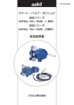
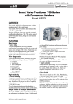
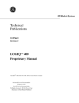
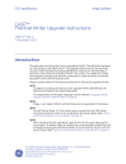
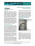
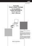
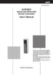
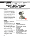
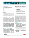
No. SS2-PVS310-0001 (Rev.1) Control Valve Maintenance Support System PLUG-IN [R 31] 1. Introduction ing and closing directions over time. (6) Stick-slip diagnostics PLUG-IN Valstaff is a valve management system that detects problems with control valves and positioners at the earliest possible stage by monitoring diagnostic parameters and other information from the Smart Valve Positioner, thereby assisting to avoid accident/failure and helping to streamline maintenance tasks by clearly presenting the information required for decision-making on control valve maintenance. The PLUG-IN Valstaff monitors diagnostic information 24 hours a day, 365 days a year by communicating with Azbil Corporation’s Smart Valve Positioner, which supports FOUNDATION™ fieldbus and HART® communication. Based on this diagnostic information, at the first sign of an abnormality, the system sends an alert in order to prompt action before the control valve can cause a problem, allowing continuously safe and secure plant operation. The PLUG-IN Valstaff also supports quick and accurate startup by automating positioner settings that adjust the control valve status, as well as automating step response tests. It also utilizes diagnostic information for routine maintenance, supporting the creation of an appropriate maintenance plan based on the degree of deterioration of control valves. Analyzes stick-slip occurrence trends. (7) Deviation Collects and compares open position settings to actual control valve open positions, and displays them in a graph. (8) Po Validity / Max. Friction diagnostics The relationship between output air pressure and Travel is compared against the value obtained during auto-setup as a standard, and displays them in a graph. (Only Smart Valve Positioner 700 series) (9) Air circuit diagnostics Calculates the shift amount from the normal value of the drive signal and the nozzle back pressure per day, and displays them in a graph. (Only Smart Valve Positioner 700 series) (10) Supply Pressure Displays the maximum value and minimum value of supply pressure per day in chronological order in a graph. (Only Smart Valve Positioner 700 series) (11) Zero Travel Count 2. Function Overview The PLUG-IN Valstaff, in combination with Azbil Corporation’s Smart Valve Positioner, achieves its functions of CV diagnostics parameter monitoring, step response test, and auto-setup by means of integration with a device management system. The maximum and minimum travel at the travel cutoff low position are successively updated, and displays the maximum and minimum travel per day in chronological order in a graph. (Only Smart Valve Positioner 700 series) (12) Temperature 2.1Online Monitoring of CV Diagnostics Parameter in Plant Operation The maximum and minimum temperature according to the temperature sensor are successively updated, and displays the maximum and minimum temperature per day in chronological order in a graph. (Only Smart Valve Positioner 700 series) By collecting diagnostic parameter data from the Smart Valve Positioner and displaying it in a graph during plant operation, the progress of control valve deterioration and the occurrence of abnormalities can be estimated while the plant is operating. The PLUG-IN Valstaff collects data from the positioner and displays the following diagnostics graphs. (1) Total stroke Totalizes the operating distances of the valve stem during valve opening position control. (2) Shut-off count Counts the number of times valves are completely closed and displays the total close counts in chronological order in a graph. (3) Cycle count Counts the number of times the control valve was reversed and displays them in chronological order in a graph. Figure 1. Stick-Slip Diagnostics Screen (4) Travel histogram Indicates the ratio of the travel value use frequency against total operating time in a particular opening position area. (5) Maximum travel speed Constantly measures the operating speed of the control valve in both the opening and closing directions, calculates the maximum speed for each day, and then displays the maximum values for open1 No. SS2-PVS310-0001 Azbil Corporation 2.2 Offline Valve Test 2.3 Auto-setup The PLUG-IN Valstaff user can execute Step Response Test and Valve Signature Test for control valves in plant shutdown. The PLUG-IN Valstaff ’s auto-setup function automatically adjusts the positioner. The behavior of a control valve during auto-setup can be monitored during the error-checking portion of the automatic adjustment process. Also, the stroke time and hysteresis data collected during auto-setup can be compared with the past test data. This comparison provides an easy way to judge deterioration and the occurrence of abnormalities in the control valve. (1) Step Response Test The PLUG-IN Valstaff user can execute a step response test for control valves when plant is in shutdown maintenance. The results, which are displayed in a graph, can be used to detect deterioration or other problems in the control valve based on changes in response waveforms compared with other timing test results of the same test pattern. In addition, quantitative dynamic characteristics data such as time constant, delay time, and settling time, which are obtained from the test result, are helpful for performance evaluation of the control valve. The user can be automatically executed this test for multiple control valves. Figure 4. Auto-setup Screen 3. System Configuration The PLUG-IN Valstaff works in conjunction with the InnovativeField Organizer (IFO) device management system made by Azbil Corporation or with the PRM® (Plant Resource Manager) made by Yokogawa Electric Corporation. Figure 2. Step Response test Screen (2) Valve Signature Test The PLUG-IN Valstaff user can execute Valve Signature Test to diagnose the control valve from characteristics between actuator pressure and valve opening. The result, which are displayed in the graph, can be used to detect deterioration or other problems in the control valve. The user can be automatically executed this test for multiple control valves. (Only Smart Valve Positioner 700 series) 3.1 With Advanced-PS (TDCS3000) By operating the PLUG-IN Valstaff on IFO, it is possible to manage control valves with a HART communication-compatible Smart Valve Positioner AVPx02. For details on system configuration, refer to the spec sheet for IFO (SS2-IFO310-0001). InnovativeField Organizer PLUG-IN LCN network HG A-MC NIM PM100 EIM PM-EX Device communication network (Ethernet) Input/output modules that comply with HART communication base unit format 4–20 mA Figure 5. PLUG-IN Valstaff Configuration for Advanced-PS/TDCS3000 Figure 3. Valve Signature Screen 2 No. SS2-PVS310-0001 Azbil Corporation 3.2 With Harmonas-DEO R410 By operating the PLUG-IN Valstaff on IFO, it is possible to manage control valves with a Smart Valve Positioner AVPx02, AVPx03 by using HART communication or FOUNDATION fieldbus. For details on system configuration, refer to the spec sheet for IFO (SS2-IFO310-0001). DCS operator station PLUG-IN (DCS external type) InnovativeField Organizer DCS Controller PLUG-IN DEO control network Device communication network (Ethernet) HC DOPC DOPC II DOPC III DOPC IV X-BUS Input/output modules that comply with HART communication base unit format 4–20mA DCS AI/AO Terminal HNU (HART Network Unit) DOFC Figure 8. IFO system configuration which is independent from DCS FOUNDATION fieldbus 3.5 When Combined with Yokogawa Electric Corporation’s PRM The PLUG-IN Valstaff control valve maintenance support system can be used in conjunction with Yokogawa Electric Corporation’s Plant Resource Manager (PRM). Figure 6. PLUG-IN Valstaff Configuration for Harmonas-DEO R410 3.3 With Harmonas-DEO except for R410 HIS PRM server HIS By operating the PLUG-IN Valstaff on IFO, it is possible to manage control valves with a Smart Valve Positioner by using HART communication. For details on system configuration, refer to the spec sheet for IFO (SS2-IFO310-0001). InnovativeField Organizer PLUG-IN DOSS DOSS FCS Azbil Corporation’s Smart Valve Positioner 700 series, 300/200 series connected using FOUNDATION fieldbus or HART DEO control network Device communication network (Ethernet) PLUG-IN works on PRM HC DOPC DOPC II DOPC III X-BUS Input/output modules that comply with HART communication base unit format 4–20mA Figure 9. PLUG-IN Valstaff configuration on PRM Server Figure 7. PLUG-IN Valstaff Configuration for Harmonas-DEO R400 or earlier 4. System Specifications 4.1 Maximum Number of Connected Smart Valve Positioners 3.4 IFO system configuration which is independent from DCS The maximum number of positioners that can be managed by the PLUG-IN Valstaff is shown below. It is dependent on the communication protocol. The PLUG-IN Valstaff can be used in conjunction with IFO independent from DCS by using HNU (HART Network Unit ). In this case, the PLUG-IN Valstaff can manage control valves with HART communication-compatible Smart Valve Positioner AVPx02. For details on system configuration, refer to the spec sheet for IFO (SS2-IFO310-0001). System Azbil Corporation’s device management system IFO Communication protocol Maximum number of managed units HART FOUNDATION fieldbus Yokogawa Electric HART Corporation’s PRM FOUNDATION fieldbus 500*1 500*1 *1: The sum of FOUNDATION fieldbus devices and HART devices. 3 No. SS2-PVS310-0001 Azbil Corporation 4.2 Application Specifications 4.3 Target Smart Valve Positioner xx With IFO xx Smart Valve Positioner 300/200 series Stick-slip diagnostics: 400 s Total stroke: 1 day *3 Model AVP302 Maximum travel speed: 1 day *3 Model AVP202 Total shut-off count: 1 day *3 Cycle count: 1 day *3 Model AVP303 Model number Model AVP203 Po Validity / Max. Friction 1 day *3 *5 diagnostics: Diagnostic parameter update interval Model number Model AVP702 Ver. 2.1 or later Zero Travel Count: 1 day *3 *5 Deviation: 1 day *3 *5 Model AVP703 Ver. 2.5 or later Temperature: 1 day *3 *5 Travel histogram: 1 month For detailed Smart Valve Positioner specifications, refer to the spec sheet for each product shown below. Model AVP302: Model AVP202: Model AVP102: Model AVP303/203: Model AVP702: Model AVP703: Fastest 50 ms AVP303 83.3 ms HART communication AVP702 Fastest 50 ms AVP302/202 83.3 ms The PLUG-IN Valstaff works on Azbil Corporation’s IFO or Yokogawa Electric Corporation’s PRM R3.10 or later. Stick-slip diagnostics: 400 s *2 *3 Total stroke: 1 day *3 System/software package InnovativeFied Organizer R31 Maximum travel speed: 1 day *3 Total shut-off count: 1 day *3 Cycle count: 1 day *3 1 day *3 *5 Zero Travel Count: 1 day *3 *5 Deviation: 1 day *3 *5 Temperature: 1 day *3 *5 Travel histogram: 1 month PRM R3.05.01 AVP703 HART communication AVP702 Fastest 50 ms AVP302/202 Fastest 5 s *4 Windows Server 2003 R2 Service Pack 2 (32-bit) Windows Vista Business Edition Service Pack 1 (32-bit) Windows Vista Business Edition Service Pack 2 (32-bit) Windows Server 2008 Standard Edition Service Pack 2 (32-bit) Windows Vista Business Edition Service Pack 2 (32-bit) RPM R3.10/R3.11 Windows Server 2008 Standard Edition Service Pack 2 (32-bit) /R3.12 Windows Server 2008 Standard Edition R2 Service Pack 1 (64-bit) Windows 7 Professional Edition Service Pack 1 (64-bit) Set Point(from DCS OP) 4 s *2 *3 and Valve opening: FOUNDATION fieldbus communication Windows 7 Professional Service Pack 1 (32-bit/64-bit) Windows Server 2003 Service Pack 2 (32-bit) Air circuit diagnostics: 1 day *3 *5 Supply Pressure: Operating System Windows XP Professional Service Pack 1 (32-bit) Po Validity / Max. Friction 1 day *3 *5 diagnostics: Device condition monitoring interval SS2-AVP302-0100 SS2-AVP202-0100 SS2-AVP102-0100 SS2-AVP303-0100 SS2-AVP702-0100 SS2-AVP703-0100 5. Operating Environment Fastest 1 s *3 xx With PRM Data sampling interval for CV step response test Internal software version 1 day *3 *5 AVP703 Diagnostic parameter update interval Ver. 2.1 or later Supply Pressure: FOUNDATION fieldbus communication Device condition monitoring interval Ver. 3.D or later (Field device revision 2 or later) xx Smart Valve Positioner 700 series Air circuit diagnostics: 1 day *3 *5 Set Point(from DCS OP) 4s and Valve opening: Data sampling interval for CV step response test Internal software version 6. License System Fastest 50 ms xx PLUG-IN Valstaff base license AVP30383.3ms *2 Model number Description FNV-IFV3xE01 PLUG-IN Valstaff R3x License 16 TAG entry edition FNV-IFV3xE02 PLUG-IN Valstaff R3x License 25 TAG License for number FNV-IFV3xE05 PLUG-IN Valstaff R3x License 50 TAG of device FNV-IFV3xE10 PLUG-IN Valstaff R3x License 100 TAG connection FNV-IFV3xE20 PLUG-IN Valstaff R3x License 200 TAG 300 s *3 *2: In the case of running on PRM, data sampling interval might be delayed by communication performance constraint. *3: Interval may require adjustment depending on the number of valve positioners connected. *4: It becomes not step response test but simplified valve test by communication performance constraint. FNV-IFV3xE30 PLUG-IN Valstaff R3x License 300 TAG FNV-IFV3xE50 PLUG-IN Valstaff R3x License 500 TAG xx PLUG-IN Valstaff DMS (Device Management System) connection license *5: Only Smart Valve Positioner 700 series Model number Description License for DMS FNV-IFV3xE-A PLUG-IN Valstaff R3x DMS connect license for IFO connection FNV-IFV3xE-B PLUG-IN Valstaff R3x DMS connect license for RPM 4 No. SS2-PVS310-0001 Azbil Corporation 7. External storage Safety precautions Automatic backup and external storage is available for control valve diagnostic data collected by PLUG-IN Valstaff operating in IFO. For automatic back-up, after conferring with the client, we can use the external storage options listed below. When using PLUG-IN Valstaff operating in PRM, please use the large-capacity storage method recommended by PRM. CAUTION Before wiring, be sure to shut off the power to all devices that require power shutoff during wiring. Failure to do so may cause device failure. If an explosion-proof field device is used, never open its cover while it is running (while power is supplied). • Imation Corporation RDX Removable HDD Storage System USB3.0/RDX HDD Media Doing so may result in an electric shock. Imation Corporation’s web site: http://www.imation.com/en-US/ For handling of this type of device, see the user’s manual for the device. CAUTION Back up data and check for viruses regularly. When using external storage for automatic back-up, keeping your PC safe is a necessity. However, please do not install anti-virus software on the PC used for IFO. Instead, do virus-checking remotely from another PC. Failure to do so may result in corrupted data or program malfunction. Do not install any anti-virus software into this PC. Check for viruses remotely from another PC. •Also, if an external storage device whose operation we have not checked is used, Azbil Corporation cannot guarantee its operation or the integrity of the data. If the lack of a guarantee is acceptable and an external storage device which we have not checked is used, please use a device that meets the following conditions at a minimum. Do not connect the PC upon which the PLUG-IN Valstaff application software is to be installed to an external network such as the Internet or a corporate intranet. If the PC is infected by a virus, the collected data may be corrupted or a program may malfunction. •Device does not require special software (do not install software other than Azbil products on the PC used for IFO). Do not install any applications except those listed below on the PC upon which the PLUG-IN Valstaff application software is to be installed. •Device does not incorporate a security function. • Device management system and associated software • PLUG-IN Valstaff application software About icons for safety precautions • Driver for the USB hard disk drive used for data backup and loading (if necessary) The safety precautions described in this document are indicated by the following icons. Please keep in mind that Azbil Corporation’s warranty does not cover any failures resulting from installation of any other applications. Warnings are indicated when mishandling this WARNING product might result in death or serious injury. CAUTION Before executing offline diagnostics, inform operators in the vicinity of control valves that the diagnostics will make the valves open and close regardless of signals from the controller. Cautions are indicated when mishandling this product might result in minor injury to the user, or only physical damage to the product. ■ Example Unexpected valve opening or closing can injure operators. The indicated action is prohibited. Before executing full stroke tests, inform operators in the vicinity of control valves that the tests will make the valves open and close regardless of signals from the controller. Be sure to follow the indicated instructions. Unexpected valve opening or closing can injure operators. Before calibrating or adjusting the positioner, changing settings, or performing other related operations, check that the intended operation will not affect the operation of the plant and change the mode to “out of service.” Before executing AutoSetup, inform operators in the vicinity of control valves that AutoSetup will open the valves from the fully closed position to the fully open position. Unexpected valve opening or closing can injure operators. When connecting the hard disk drive to another PC, perform a virus check before reconnecting it to the device management system. 5 No. SS2-PVS310-0001 Azbil Corporation 6 No. SS2-PVS310-0001 Azbil Corporation 7 No. SS2-PVS310-0001 Azbil Corporation • • • • • • Valstaff ™ is a trademark of the Azbil Corporation. PRM® is a trademark of Yokogawa Electric Corporation in the USA and other countries. FONDATION™ is a trademark of Fieldbus Foundation. HART® is a trademark of HART Communication Foundation. Windows 7, Windows XP, Windows Vista, Windows Server 2003 and Windows Server 2008 are trademarks of Microsoft Corporation in the USA and other countries. Other product names, model nos., and company names may be trademarks of the respective company. Please read the "Terms and Conditions" from the following URL before ordering or use: http://www.azbil.com/products/bi/order.html Specifications are subject to change without notice. 1-12-2 Kawana, Fujisawa Kanagawa 251-8522 Japan URL: http://www.azbil.com/ (10) 1st Edition: Issued in Aug. 2014 2nd Edition: Issued in Dec. 2014 8 No part of this publication may be reproduced or duplicated without the prior written permission of Azbil Corporation.