
1
ite®
OPERATOR'S MANUAL
4-Cycle High-Wheel Field Trimmer
UT13144
Your weed trimmer has been engineered and manufactured to our high standard for dependability, ease
of operation, and operator safety.
A
WARNING: To reduce the risk of injury, the user must read and understand the operator's manual before
. . using this product.
Thank you for your purchase.
SAVE THIS MANUAL FOR FUTURE REFERENCE
11f02/200 6
TABLE OF CONTENTS
•
Genera l Safety Rules
1-2
•
Specific Safety Rules
3
.~m~ls
~5
•
Features
6
•
Assembly
7
•
Operation
8-11
•
Slope Guide
12
•
Maintenance
13-1 7
•
Troubleshoo ting
18-19
•
Replacement Parts List
20-22
•
Limited Warranty
23-24
•
Customer Service
'-
24
INTRODUCTION
.....1
This tool has many features for making its use more pleasant and enjoyable. Safety, perform ance, and dependability have
been given top priority in the design of this product making it easy to maintain and operate.
GENERAL SAFETY RULES
This book is written for a person with some mechan ical ability. Like most service books , not all the steps are described.
Steps on how to loosen or tighten fasteners are steps anyone
can follow with some mechanical ability. Read and follow
these instructions before you use the unit.
Know your product: If you understand the unit and how the
unit ope rates, you will get the best performance. As you read
this manual, compare the illustrations to the unit. Learn the
location and the functions of the contro ls. To help prevent
an accident, follow the operating instructions and the safety
rules. Keep this manual for future reference.
AWARNING
To prevent accidental starting when setting up,
transporting, adjusting or making repairs, always
disconnect spark plug wire and put wire where it cannot
contact the spark plug.
SAFE OPERATION PRACTICES BEFORE USE
Read, understand, and follow all instructions on the
machine and in the manuals. Be thoroughly familiar with
the controls and the proper use of the trimmer before
starting. Know how to stop the trimmer and disengage the
controls quickly.
Familiarize yourself with all the safety and operating decals
on this equipment.
Thoroughly inspect the area where the trimmer is to be
used and remove all foreign objects. Your equipment can
propel small objects at high speed causing personal injury
or property damage. Stay away from breaka ble objects,
such as house windows, auto glass, greenhouses, etc.
Inspect the throttl e control lever and cable. Make sure
that the cable is free and that the lever is not damaged.
Also check the cable linkage running to the carburetor for
kinks, loose fittings, and obstructions. Verify that the start
lever is working properly.
Check that all nuts and bolts are tight and equipment is in
good condit ion. Check mounting hardware on trimmer
head every time you change trimmer line prior to each use.
IMPORTANT: Many units are not assembled and are sold in
cartons. It is the responsibility of the operator to make sure
the assembly instructions in this manual are exactly followed .
Other units are purchased in an assembled condition. On
assem bled units, it is the responsibility of the operator to
make sure the unit is correctly assembled. The operator
must carefully check the unit according to the instructions in
this manual before it is first used.
RESPONSIBILITY OF THE OPERATOR
The responsibility of the operator is to follow the instructions
below :
1. Carefully read and follow the rules for safe operation.
2. Follow all the assembly and preparation instructions.
3. Regularly inspect the trimmer. Make sure parts are not
bent, damaged, or loose.
4. Use this equipment for its intended purpose only.
5. Make sure that the operator of the unit knows how to
correctly use all standard and accessory equipment.
6. Operate the unit only with guards, shields , and other safety
items in place and working correctly.
7. Correctly adjust the unit.
8. Service the unit only with authorized or approved
replaceme nt parts.
9. Complete all maintenance on the unit.
OPERATION SAFETY
AWARNING
Look for this symbol to point out important safety
precautions. It means: " Attention! Become Alert! Your
Safety Is Involve d."
AWARNING
Engine Exhaust, some of its constitue nts, and certain
vehicle components contain or emit chemicals known to
the State of California to cause cancer and birth defects
or other reproductive harm .
Battery posts, terminals and related accesso ries contain
lead and lead com pounds, chemicals known to the State
of California to cause cancer and birth defects or other
reproductive harm. WASH HANDS AFTER HANDLIN G.
Page 1
Never allow children or young teenagers to operate the
trimmer.
Keep area of operation clear of all bystanders, particularly
small children and pets.
Keep bystanders at least 50 It (15 m) away.
Only allow responsible individuals, who are familiar with
the instructions, to operate the trimmer.
Do not operate the trimmer while under the influence of
alcohol, drugs, or other medication which can cause
drowsiness or affect your ability to operate this machine
safely.
Do not use this machine if you are mentally or physica lly
unable to operate the machine safely.
Always wea r ANSI compliant safety goggles or safety
glasses with side shields when operating trimmer to
protect your eyes from foreign objects, which can be
thrown from the unit.
Wear appropriate clothing such as a long sleeved shirt
or jacket. Also wear long trousers or slacks. Do NOT
wear shorts . Do NOT wear loose clothing, which could get
caught in this equipment.
Always wea r work gloves and sturdy footwea r such as
leather work shoes or short boots. These will protect
ankles and shins from small sticks, splinters, and other
flying debris, and improve traction.
It is advisable to wear protective headgear to protect
against being struck by small flying particles, or being
GENERAL SAFETY RULES
struck by low hanging branches, twigs, or other objects ,
which may be unnoticed by the operator.
Do not put hands or feet near or under rotating parts.
When crossing gravel drives, walks, or roads , stop the
rotating trimmer head and wait for the trimm er lines to
stop. Exercise extreme caution. Stay alert for hidden
hazards or traffic.
Exercise caution to avoid Slipping or falling. Never operate
trimmer in wet grass. Always be sure of your footing; keep
a firm hold on the handle and walk; never run.
Look behind and use care when backing.
Never operate the trimmer without good visibility or light.
Do not run the engine indoors or inside a closed area. The
exhaust fumes are dangerous , containing CARBON
MONOX IDE, an ODORLESS AND DEADLY GAS.
Never leave the trimmer unattended when the engine is
running. Stop the engine and make sure all moving parts
Page 2
have stoppe d. Remove the wire from the spark plug.
If the trimmer should start to vibrate abnormally, stop the
engine, disconnect the spark plug wire and prevent it from
touching the spark plug. Check immediately for the cause.
Vibration is generally a warn ing of trouble.
Watch for holes, ruts, bumps, or other rough ground. Tall
grass can hide obstacles.
Do not trim excessively steep slopes (maximu m 15
degrees). See the "Slope Guide" in the back of this
manual to check a slope.
Always trim across the face of slope; never up and dow n.
Exercise extreme caution when changing direction on
slopes. If you are uneasy on a slope, do NOT trim it.
Do NOT trim near drop-otis , ditches, or embankments.
The operator could lose footing or balance.
SPECIFIC SAFETY RULES
is running except when specifically recommen ded by the
manufacturer.
Keep the trimmer in safe working condition. Check all
faste ners at frequent intervals for proper tightness.
When servicing or repairing the trimmer, do not tip the
machine over or up unless specifically instructed to do so
in this Manual. Service and repair procedures can be
do ne with the trimmer in an upright position. Some
procedures will be easier if the machine is lifted on a
raised platform or working surface .
Use only original equipment or authorized replacement
parts.
Never tampe r with safety devices. Check their proper
operation regularly.
Do not change the engine gove rnor setting or over-speed
engine.
Clean and replace safety and instruction decals as
necessary.
To guard aga inst engine over-heating, always have engine
debris filter mounted and clean.
FUEL SAFETY
Handle fuel with care; it is highly flammab le.
Use an approved container.
Check fuel supply before each use, allowing space for
expansio n as the heat of the engine andlo r sun can cause
fuel to expa nd.
Fill fuel tank outdoors with extreme care . Never fill fuel
tank indoors.
Never remove gas cap or add fuel with the engine running.
Allow engine to cool before refueling.
Do not smoke while refueling.
After refueling, replace fuel tank cap secure ly and wipe up
spilled fuel.
Never store fuel or trimmer with fuel in the tank inside a
building where fumes may reach an open flame.
STORAGE SAFETY
Always refer to the operator's manual instructions for
important details if the trimm er is to be stored for an
extended period.
Never store the trimmer with fuel in the fuel tank inside a
building where ignition sources are present such as water
heaters, space heaters, clothes dryers , etc.
To reduce fire hazard, keep trimmer free of grass, leaves,
or other debris build-up.
Allow the engine to cool before storing in any enclos ure.
CHILDREN SAFETY
REPAIR, MAINTAINANCE, AND ADJUSTMENT
SAFETY
After striking a foreign object, stop the engine. Remove
the wire from the spark plug and keep the wire away from
the plug to prevent accidental starting. Thoroughly inspect
the trimmer for any damage. If damaged, have the
equipment repaired by a trained technician before
restarting and operating.
Stop the engine before cleaning, repairing, or inspecting
the unit. Make sure all moving parts have stopped. Let
the engine cool, disconnect the spark plug wire and move
it away from the spark plug.
Never atte mpt to make any adjustments while the engine
Page 3
Tragic accidents can occur if the operator is not alert to the
presence of children. Children are often attracted to the
trimmer and the trimmin g activity.
Keep children out of the trimming area and under the
watchful care of a responsible adult.
Never assume that children will remain where you last saw
them.
Be alert and turn trimmer off if children enter the area.
Before and while moving backwards, look behind and
dow n for small children.
Never allow children to operate the trimmer.
Use extra care when operating near blind corners, shrubs,
trees, or other objects that may obstruct vision.
SYMBOLS
CONTROL AND OPERATING SYMBOLS
IMPORTANT:
Many of the following symbols are located on your unit or on literature supplied with the product. Before you operate the unit,
learn and understand the purpose for each symbol.
SLOW
~
<I>
FAST
ENGINE STOP
j
OIL
ENGINE STOP
~€Jffi:~
FUEL
ENGAGE
DISENGAGE
SAFETY ALERT SYMBOLS
Indicates danger, warning, or caution. Attention is required in order to avoid serious personal injury. The signal word
(DANGER, WARNING, OR CAUTION) is used with the alert symbol to alert you to special instruction about a particular
operation that may be hazardous if performed incorrectly or carelessly. Observe them carefully.
SYMBOL
A
A
A
DANGER
WARNING
CAUTION
CAUTION
EXPLANATION
Failure to obey a safety warning will result in serious personal injuries or deaths.
Failure to obey a safety warni ng can result in serious personal injuries or deaths.
Failure to obey a safety warning may result in minor or moderate injuries.
When used without the alert symbol, could result in damage to your engine or other
property.
Page 4
SYMBOLS
SAFETY WARNING SYMBOLS
SYMBOL
A
m
~ I-~
DESCRIPTION
Indicates WARNING, DANGER, or CAUTION.
Read operator's manual before operating this machine. Failure to follow directions could result
in serious injury.
Thrown objects. Keep bystanders at least 50 ft (15 m) away. Do not use if children are present.
Remove all objects which could be thrown by machine. Read operator's manual before operating
this machine.
@
Do NOT trim up and down slopes. Trim across slopes.
~t
Rotating parts can cause serious injury. Keep away from rotating parts. Stop engine and
disconnect spark plug wire before making adjustments.
e:J6
Wear eye protection complying with ANSI 287.1 and hearing protection.
Disconnect spark plug wire before servicing unit.
~
fi
Direction of rotating line.
*d
Engine emits carbon monoxide. Do NOT run indoors or in enclosed area .
.M
To reduce risk of fire, clean spilled gas and oil and keep unit free from debris. Gasoli ne is
extremely flamm mable. Allow machine to cool before refueling.
Do NOT touch hot muffler or cylinder. These parts are extremely hot from operation and may
remain hot for a short time after operatio n.
Page S
FEATURES
Engine Displacement.
160cc Oil Capacity
Gasoline Capacity
16.9 oz. [500 ml]
0.95 qt. [0.9 L] Spark Plug Model.
Gasoline Type
F6RTC
Unleaded Regular Spark Plug Gap
Oil Type (API SG-SL)
0.027-0.031 in. [0.7-0.8 mm]
SAE 30 (above 32 deg rees) 1 Trimmer Line Length
21.5 in. [546 mm]
... ... ... .. . .. ...... . . . SAE 5W-30 (below 32 degrees) Trimmer Line
0.155 in. [4 mm]
KNOW YOUR TRIMMER
READ THE OPERATOR'S MANUAL AND ALL SAFETY RULES BEFORE YOU OPERATE the trimmer. To familiarize yourself
with the location of the controls, compare Figure 1 with your trimmer. Save this manual for future reference.
dt---_.. Throttle Control Lever - - -.n
+t--- Start Lever
r
I
Trimmer Head Drive
Lever
Recoil Starter Handle
Primer Button
Shield Edge Guard
Figure 1
Trimmer Head Drive Lever Engages the rotation of the
trimmer head.
Prim er Button Injects fuel directly into the carburetor for
faster starts. (See Figure 5)
Start Leve r Release to stop the rotation of the trimmer
head.
Recoil Starter Handle The engine is equipped with an easy
pull recoil starter.
Throttle Control Lever Controls the speed or stops the
engine.
Shield Edge Guard Protects the shield by automatically
cutting the line to the correct length.
Page 6
ASSEMBLY
Read and follow the assembly and adjustment instructions.
Do not discard any parts or materials until the unit is assembled .
NOTE: Torque is measured in foot-pounds (metric unit is
Nm). This measurement desc ribes how tight a nut or bolt
must be. The torque is measured with a torque wrench.
A WARNING
Always wear ANSI compliant safety glasses or eye
shields while assemb ling the trimmer.
The following components will be found in parts bag with
quantities in ( ):
(1) Field Trimmer Operator's Manual
(1) Engine Operator's Manual
(1)500 ml Bottie of Oil
(1)T-Handle Wrench
(4)0 .155 in. Trimmer Lines (4 lines make 2 sets)
TOOLS REQUIRED
(1) Utility Knife to Cut Carton
(1)Oi l Funnel
(1)Torque Wrench to Check Fastener Tightness
(1)T-Handle Wrench (included in parts bag)
ADJUST THE HANDLE
1. Hold the handle with one hand and loosen both handle
adjustment knobs until the ratchet teeth are disengaged.
Do not remove the handle adjustment knobs.
(See Figure 2)
2. Press sides of handle apart and rotate the handle to
the desired position behind the trimmer.
3. Stand in the operator's position behind the trimm er to
make sure handle is adjusted to a comforta ble position
4. Tighten the handle adjustment knobs to 13-15 foot-pound s
[18-20 Nm].
5. To attach the recoil start handle to the rope guide , twist the
rope through the rope guide mounted on the right side of
the handle.
A WARNING
Handle
-- 1__
Before do ing any assembly or maintenance to the unit,
remove the wire from the spark plug.
II'" -
-
-
- _......
1\
I
!I I
I
Rope Guide
I,
I
,
,I
Recoil Start
Handle
I
I
Handle Pivot
,'
II
Handle
Adjustment
Knob
Figure 2
Page 7
OPERATION
ENGINE PREPARATION
ENGINE DOES NOT CONTAIN OIL OR GASOLINE WHEN
SHIPPED
See the engine manufacturer's instructions for the type of
gasoline and oil to use. Before you use the unit, read the
information on safety, operation, maintenance, and storage.
This trimmer was shipped with a 500 ml container of SAE30
motor oil. This oil is to be added to the engine before operat ing.
Follow the following procedure to fill the crankcase with oil.
FIRST TIME FILL
1. Place the trimmer on a level surface.
2. Remove the oil fill cap/dipstick.
NOTE: the crankcase is shipped empty, so fill with 500 ml of oil.
3. When adding oil, use a funnel to reduce spillage.
4. DO NOT OVERFILL. Check the oil level by following the
instructions below.
TO CHECK THE OIL LEVEL AND FILL TO PROPER
LEVEL
1. Place the trimmer on a level surface.
2. Remove the oil fill cap/dipstick and wipe clean with cloth.
3. Replace dipstick and do NOT screw it. Remove and
check oil level.
4. When oil level is full, the oil will be at upper limit on dip
stick. (See Figure 3)
5. If the oil level is near or below the lower limit mark on the
dipstick (See Figure 3), add oil slowly and recheck until
oil level reaches upper limit of dipstick. DO NOT OVER
FILL.
6. Replace and tighten dipstick.
7. Clean up any spilled oil.
CHECKLIST
For the best performance and satisfaction from this quality product, please review the following checklist before you
operate the trimmer:
All asse mbly instructions have been completed.
Check carton to make sure no parts are remaining.
All fasteners have been properly tightened.
As you learn how to use the trimmer, pay extra attention to
the following importa nt items :
Engine oil is at proper level.
Fuel tank is filled with a fresh, clean, regular unleaded
gasoline.
Become familiar and understand the function of all
controls. Before you start the engine, operate all controls.
FILLING TANK
1. Clean surface around fuel cap to prevent contanimation.
2. Loosen fuel cap slowly. Rest the cap on a clean surface.
3. Carefully pour fuel into the tank. Avoid spillage .
4. Prior to replacing the fuel cap, clea n and inspect the
gasket.
5. Immediately replace fuel cap and hand tighten. Wipe up
any spillage.
NOTE: It is normal for smoke to be emitted from a new engine
after the first use.
NOTE: When adding oil, frequently insert the oil fill cap/dipstick
and check the amount of oil in the engine.
DO NOT OVERFILL. (See Figure 4)
Upper Limit ~
/
Lower Li mit -------../'
A, WARNING
Follow the engine manufacturer's instructio ns for the type
of gasoline and oil to use. Always use a safety
gasoline container. Do not smoke when adding gasoline
to the engine. When inside an enclosure, do not fill with
gasoline. Before you add gasoline, stop the engine. Let
the engine cool for severa l minutes.
IMPORTA NT: This unit is equipped with an internal combustion
engine and must not be used on or near any unimproved
forest-covered, brush-covered or grass-covered land unless
the engine's exhaust system is equipped with a spark arrestor
meeting applicable local or state laws. If a spark arrestor is
used, the operator must maintain it in effective working order.
In the State of California the above is required by law (Section
4442 of the California Public Resources Code). Other states
may have similar laws. Federal laws apply on federal lands.
See an Authorized Service Center for a spark arrestor for the
muffler.
Page 8
Figure 3
rf1~o Fuel Tank Cap
OPERATION
A
WARNING
Debri s thro wn from the trimmer can result in foreign
objects bein g thro wn into eyes , which can cause seve re
eye damage. Always wear ANSI co mpliant safety
glasses or eye shields when operating the trimm er. If yo u
wear eyeg lasses, put an ANSI cert ified Wide Vision
Safety Mask over yo ur eyeg lasses.
~Q~It--Jrt;Lft-primer
Button
HOW TO USE THE PRIMER BUTTON
Figure 5
NOTE: Do not use the primer button to restart a war m engine after a short shutdow n.
When starting a cold engine, push the prime r button th ree
tim es (See Figure 5). Wait approx imate ly two seco nds
between eac h push .
HOW TO USE THE THROTTLE CONTROL
1. Du ring normal use, set the throttl e control lever in the
FAST position to run the engine at full speed .
2. Pull the th rottl e co ntrol leve r back to decrease engine
speed . Push the throttle co ntrol lever forward to incre ase
engine speed .
3. To stop engine , pull the throttle control lever co mpletely
back to the STOP position. (See Figur e 6)
Figure 6
HOW TO START THE ENGINE
NOTE: DO NOT BE ALARM ED; you r engi ne w ill smoke the
first time it is started. It is burn ing off the prot ect ive coati ng
that is on the internal engine parts.
NOTE: Make sure engine is level before starting.
A CAUTION
Never leave the trimmer unattended while the engi ne is
runni ng. Wait for the trimm er lines to stop rotat ion.
1. Before each use, remove the debri s from the debris
scree n. Debris can cause the engi ne to overhea t. Wipe the
de bris scree n w ith a cloth or paper towe l.
2 . Mov e the throttle co ntro l lever forward to the STA RT or
FAST position.
3. Make sure the fuel line valve is turned on (the knob should
be horizo ntal). (See Figure 7)
4 . To start a cold engine , push the prime r butto n three tim es.
Wait two seco nds between eac h push of the primer butto n.
5. Firmly hold the reco il starter handle w ith your right ha nd .
(See Figure 8)
6. Pull the recoil starter slow ly, until you feel tension in the
starter rope . Th en quic kly pull the recoil starte r handle
to co mpletely unwind the starter rope . DO NOT allow the
starter rope to snap back. Let the sta rter rope slow ly
rewind as you hold the recoil sta rter handle.
7 . If eng ine fails to start afte r three pulls, push the primer
butto n two tim es and agai n pull the recoil sta rter hand le .
8 . If eng ine fails to start after 5 or 6 more tries, see the
instruct ion in the "Troubleshooting Chart ".
Page 9
Figure 7
Recoil Starter
Handle
Figure 8
OPERATION
A WARNING
Handle
Never run the engine indoors or in a poorly ventilated
area. Engine exhaust contains carbon monoxide, an
odorless and deadly gas. Keep hands, feet, hair and
loose clothing away from the trimmer and any moving
parts on the engine. Avoid the muffler and surrounding
areas. Temperatures may exceed 150 degrees.
HOW TO STOP THE ENGINE
Move the throttle control lever completely back to the STOP
position.
A CAUTION
Trimmer Head
Drive Lever
The trimmer head will continue to rotate for several
seconds after the engine has stopped.
Figure 9
Height of Cu t Positions
~\:
HOW TO STOP THE TRIMMER HEAD
p
~
~
~
Release the start lever. It will return to its position and
disengage the trimmer head.
~
=
p
Set Screws
HOW TO USE THE TRIMMER HEAD DRIVE
LEVER
1. To engage the trimmer head, hold the start lever against
the handle. Move the trimmer head drive lever forward
to engage the trimmer head. (See Figure 9)
Height Guide
T-Handle Wrench
HOW TO SET THE HEIGHT OF CUT
A CAUTION
Before you set the height of cut, stop the engine. Wait
for all moving parts to stop. Allow engine to cool and
disconnect the spark plug wire.
Figure 10
The height of cut can be set from 1112 to 3 in. [38-76 mm].
Recommended cutting height for the average yard is 2 in.
[51 mm].
1. Use the T-Wrench, found in a parts bag, to loosen the (2)
set screws . (See Figure 10)
NOTE : The (2) set screws are only on one side of the
trimmer head. If you don't see the set screws, check the
opposite side. Both set screws need to be loosened to
change the height of the cut.
2. Slide the trimmer head up or down for desired height of
cut.
3. Tighten both set screws to 2.6 - 3.7 foot-pounds (3.5-5 Nm).
Page 10
OPERATION
TRIMMING TIPS
A
WARNING
Debris such as sticks , gravel, and rocks can be thrown
with sufficient force to cause personal injury or prope rty
damage.
Set the throttle control in the FAST position. The faste r the
engine runs, the faster the trimmer head will rotate. If the
weeds or grass are tall and thick, operate the trimmer at a
slower walking speed.
Frequently clean the trimmer to remove any grass build
up. See the Maintenance section for details.
For best results and longer lasting line, use the ends of the
line to do the cutting. This is easily done by moving
slowly through very thick or heavy weeds.
If the trimmer lines become too short, it will take longer to
complete this job. If the trimmer lines are worn to less
than half their original length, change to a new trimmer
line. See "How to Replace the Trimmer Line" in the
Maintenance section.
Do not trim on excess ively steep slopes . See Slope
Guide. If a slope is difficult to stand on, do not trim it.
Do not trim on slopes when the ground is slippery or wet.
Trim across the face of a slope, not up and down.
Trimmer head contact to concrete, asphalt and harder
surfaces may create premature wear to the height guide.
Page 11
SLOPE GUIDE
SIG HT AND HOLD THIS GUIDE LEV EL WITH A VERT ICAL TREE, A CO RNER
OF A STRU CTURE, A POWER LINE POL E, OR A FENCE.
Operate a trimmer across the face of slopes, never up or down slopes .
Use this guide and do not trim on a slope greater than 15 degrees .
A WARNING!
Use extreme care at all times and avoid sudden turns or maneuvers. Follow
other instructions in this manua l for safety in trimming on slopes. Operate
a trimmer acro ss the face of slopes, never up or down slopes . Use extra
care when operating on or near slopes and obstructions.
A 10-degree slope is a hill that increases in height at app roximately 1.7 feet in 10
feet.
A 15-degree slope is a hill that increases in height at approx imate ly 2.5 feet in 10
feet.
l
i\)
.A
,/ -- II
1-· -_
I
Operate a trimm er acros s the face of
slopes , never up or down slopes.
--r--.o" v ~
1'=QlIIII:
~ .,
i
$
'»",,~
I
~
15 Degrees
MAINTENANCE
PERIODIC MAINTENANCE SCHEDULE TABLE
Service RecordsFill in dates as you
complete regular
se rvice
Check Engine Oil
Level
Before
Each
Use
,;
Check Trimmer Head
Engagement
,;
Check Nuts and Bolts
Every
25
Hours
Every
100
Hours
See Note
Before Storage
Service Dates
,;
Check Trimmer Lines
Engine/Machine
Cleaning
Every
5
Hours
1
,;
2
,;
Check Spark Plug
,;
Change Engine Oil
,;
Service Air Filter
,;
Lubricate Jackshaft
Assemb ly
Lubricate Wheel
Bearings
3
,;
,;
Note 1 When old line is half the original length, replace with new line.
Note 2 Clean daily if used in extremely dusty or dirty conditio ns. Clean grass and debris build up off of the debris screen.
Note 3 Change more often if used in extremely dusty or dirty conditions.
GENERAL RECOMMENDATIONS
The warranty on this trimmer does not cove r items that have been subjected to operator abuse or negligence. To receive full
value from the warranty, the operator must maintain the trimmer as instructed in this manual.
Some adjustments must be made periodically to properly maintain your trimmer .
All adjustments in the Maintenance section of this manual must be checked at least once each seaso n.
Page 13
MAINTENANCE
ENGINE MAINTENANCE
Use the following maintenance section to keep your unit in
good operating condition. All the maintenance information for
the engine is in the "Engine Operator's Manual". Before you
start the engine, read this manual.
HOW TO CHANGE THE OIL
1.
2.
3.
4.
5.
6.
7.
Shut off engine and wait for it to cool.
Disconnect spark plug wire from the spark plug.
Remove the oil drain plug. (See Figure 11)
Drain all the engine oil into a flat pan.
Install the oil drain plug. Make sure fhe oil drain plug is tight.
Remove the dipstick.
Fill the engine crankcase. DO NOT OVERFILL. Refer
to Engine Preparation section for instructions on filling oil
to proper level.
8. Connect the spark plug wire to the spark plug.
NOTE: View is bottom of the unit
Figure 11
A WARNING
Before you inspect, clea n, or service the trimmer, stop
the engine. Make sure that all moving parts have
stopped . Disconnect the wire from the spark plug.
Page 14
MAINTENANCE
HOW TO REPLACE THE TRIMMER LINE
When the trimmer line becomes worn to half the original
length, replace the trimmer line. For the best performance,
use a heavy gauge 0.155 in. [4 mm] trimmer line.
1. Stop the engine. Wait for all moving parts to stop.
Disconnect the wire from the spark plug.
2. Remove the worn trimmer line from line retainer.
3. Cut the length of the trimme r line to 21.5 in. [546 mm).
Use the length guide; located on the shield to make sure
the trimmer line is the correct length. (See Figure 12)
Do not allow the length of the lines to vary more than one
inch. Make sure the trimmer head is balanced and does
not vibrate.
4. Thread the ends of the new trimmer line through the out
side loops. (See Figure 13)
5. Take the ends of the line, cross over the line retainer, and
thread the ends through the center hole. (See Figure 14)
6. Then, check to make sure that the ends of the line are
even. (See Figure 15)
7. Follow same steps for line on alternate side.
Figure 13
IMPORTANT: To extend the life of the trimmer line, keep the
trimmer line moist. If not kept moist, the nylon trimmer line
will become dry and brittle. Keep extra trimmer line in a can
of water. The line will then stay flexible and easy to change.
A flexible line will also last much longer.
Figure 14
Figure 12
Page 15
Figure 15
MAINTENANCE
HOW TO REPLACE THE DRIVE BELT
Trimmer Housing
A WARNING
Before you remove the drive belt, disconnect the wire from
the spark plug.
To replace the drive belt, the trimmer head and shield must
be removed as follows.
1. Remove the two fasteners that hold the rear of the shield
to the trimmer housing. (See Figure 16)
2. Remove the four fasteners that hold the front of the shield
and trimmer head to the trimmer housing.
3. Remove the "V" Pulley from the idler bracket.
(See Figure 17)
4. Raise the front of the trimmer housing and remove the
drive belt. Do not bend the belt guides .
NOTE: Make sure you replace the drive belt only with a
replaceme nt belt from the factory. The length of the belt is
45.67±0.1 in. [1160±2.5mm], the angle is 37" , and the section
is 3L.
5. To assemble the drive belt, reverse the above steps.
6. The torque specs are 9.6-14.8 foot-pounds [13-20 Nm] for
the shield fasteners, 27-33 foot-pounds [36.6-44.7 Nml for
the drive pulley mounting bolt, and 18-25 foot-pounds
[24.4-34 Nm] for the trimmer head bolts.
7. Check the routing of the drive belt. Make sure the drive
belt is inside of all belt guides and that the belt is not
twisted. (See Figure 17)
Trimmer Head
Figure 16
IMPORTANT: Test the drive system. Start the engine and
move the throttle control to the FAST position. Engage and
disengage the trimmer head several times. When disengaged, make sure the trimmer head completely stops when
resting on the ground. If the trimmer head continues to
rotate , take the trimmer to an authorized Service Center.
Mounting Bolt
1111111
Drive Pulley
NOTE: View is bottom of the unit
Page 16
Figure 17
MAINTENANCE
3.
STORAGE
A WARNING
Never store the trimmer indoors with fuel in the fuel tank.
Never store in an enclosed , poorly ventilated area where
fumes could reach an open flame, a spark or a pilot light
as on a furnace, water heater or clothes dryer. Allow
engine to cool before storing unit.
4.
5.
6.
A WARNING
Do not remove gasoline while inside a building, near a
fire, or while you smoke. Gasoline fumes can cause an
explosion or a fire.
NOTE: A yearly checkup or tune-up at an authorized service
center will make sure that the trimmer will provide maximum
performance for the next season.
7.
8.
9.
10.
11 .
IMPORTA NT: It is important to prevent gum deposits from
forming in fuel system parts such as the carburetor, fuel
filter, fuel hose, and tank during storage. Also, using alcohol-blended fuels (called gasoho l, ethanol, or methanol) can
attract moisture, which leads to separation and formation of
acids during storage. Acidic gas can damage the fuel system
of an engine while in storage.
When the trimmer is put in storage for thirty days or more,
follow the steps below to make sure the trimmer is in good
condition the following season.
1. Let the engine run until it is out of gasoline.
2. Change the oil by following instructions under Engine
Maintenance.
Page 17
Remove the spark plug from the cylinder. Pour one
ounce of oil into the cylinder. Slowly pull the recoil-start
handle so that the oil will protect the cylinder. Install a
new spark plug in the cylinder. Pull recoil-start handle
slowly a few times to distribute oil.
Clean the dirt and debris from the cylinder cooling fins
and the engine housing.
Completely clean the trimmer. Remove all dirt, grease,
leaves, etc.
Check the trimmer for worn or damaged parts. Have
damaged parts replaced if necessary.
Tighten all loose hardware .
Apply lubrication as directed in Maintenance section.
Put the unit in a building that has good ventilation.
Cover the trimmer with a suitable protective cover that
does not retain moisture. Do not use plastic. Plastic can
not breathe which allows condensation to form and will
cause your unit to rust.
If desired, fold the handle down for storage. Refer to
the "Adjust the Handle" directions in the Assembly
section. When folding the handle for storage or
transportation, be sure to fold the handle as shown or you
may damage the control cables .
TROUBLESHOOTING
(
Problem
Engine does not start
Engine runs poorly
Engine over heats
Engine will not stop
Possible Cause
Solution
Spark plug wire disconnected
Connect spark plug.
Engine not primed
Prime engine.
Defective or incorrectly gapped spark plug
Inspect or replace spark plug.
Fuel tank empty or low
Add fuel.
Dirty carb uretor or fuel line
Clean carburetor or fuel line.
Carburetor dirty
For carb uretor clea ning, take the unit to an
Authorized Service Center.
Engine flooded
Wait seve ral minutes before sta rting.
Throttle control lever in incorrect position
Move th rottle lever to FAST or START position.
Stale gasol ine
Drain old gaso line and add fresh gasoline.
Defective throt tle control lever or wire
Inspect leverand wire. Replace if damaged or defective.
Dirty air filter
Replace air filter.
Sad spar k plug
Replace spark plug.
Dirty air filter
Replace air filter.
Carburetor out of adjustment
Adjust carburetor. Take the unit to an authorized
Service Center.
Stale gasol ine
Drain old gaso line and add fresh gasoline.
Engine cool ing system clogged
Clean eng ine screen and cooling fins.
Engine cool ing system clogged
Clean debris system and engine cooling fins.
Carburetor out of adjustment
Adjust carburetor. Take the unit to an authorized
Service Center.
Oil level is low.
Add oil.
Defective throt tle control lever or wire.
Inspect and replace dam aged parts .
Throttle not adjusted proper ly.
Move throttle to the full OFF position .
Trimmer line length is too short
Correct line length is 21.5 inches. When less
than 1/2 this length, replace the line.
Engine not set at FAST speed
Move engine throttle lever to FAST position.
running
Poor trimming
performance
Page 18
)
TROUBLESHOOTING
(
Problem
Trimmer vibrates
Trimmer head does not
retain line
Possible Cause
Solution
)
Set screws for trimmer head is loose
Tighten set screw with T-handle wrench.
Trimmer line lengths are substantially different
Adjust trimmer line to approximately equa lengths.
Loose nuts or bolts
Check all bolts and nuts, including eng ine bolts.
Broken trimmer head
Replace broken part.
Trimmer line not properly attached
Follow instructions on deca l or in the Service
section of the owner's manual.
Broken line retainer
Replace the trimmer head assembly.
Trim mer line not correct size
Use a 0.155 in. (4 mm) trimmer line.
Page 19
REPLACEMENT PARTS LIST
Engine and Pulley Assembly
Ref No.
Service No.
Description
A100535
Engine
2
A100536
Pulley,Engine
3
A100537
Lock Washer, 0 10
4
A100538
Bolt
5
A100539
Belt, Trimmer
6
A100540
Bolt
Ref No.
Service No.
Qty.
6-i
2
3 --~
4
5
----fl
Handle Assembly
r<' ~
16
-1
9
1
4
8
4
VaI
5
(t
I ~'\
5
6
10
"'3
\
Page 20
Description
Qty.
A100541
Upper Handle
2
A100542
Lever, Stop
3
A100543
Lower Handle
4
A100544
Pivot, Handle
4
5
A100545
Washer, Spring
2
6
A100546
Washer
2
7
A100547
Screw
4
8
A100548
Tie, Cable
3
9
A100549
G uide, Rop e
10
A100550
Knob, Handle
11
A100551
Control, Throttle
12
A100552
Cable, Control Latching
13
A100553
Tubing Foam
14
A100554
Bolt, M8x85
2
15
A100506
Nut, M6
3
16
A100555
Bolt, M6x50
2
1
2
REPLACEMENT PARTS LIST
Wheel Assembly
Ref No.
,
~~
2
Q
7
~
Service No.
Desc ription
Qly.
A100556
Spacer
2
2
A100557
Washer, Spring
2
3
A100458
Boll , M8x16
4
4
A100558
Assembly, Axle & Bracket
2
5
A100559
Wheel & Tire
2
6
A100560
Bearing
4
7
A100462
Nut, M10
2
Ref No.
Service No.
4
6
6
5
Handle Assembly
2
12
8
Page 2 1
Descriplion
Qly.
A100561
Frame, Trimmer
2
A100562
Spacer Assemb ly,
Jacks haft
3
A100563
Screw
4
A100564
Bracket, Idler Assembly
5
A100565
Pulley, Idler
6
A100566
"V" Pulley
7
A100567
Shield, Trimmer
8
A100568
Blade
9
A100569
Bolt
10
A100570
Spring, Extension
11
A100571
Shied, Trailing
12
A100572
Flap, Debris
13
A100573
Screw
14
A100574
Boll , Carriage, M6x283
15
A100506
Nut, M6
16
A100462
Nut, M10
3
17
A100575
Screw, ST4.8x12
4
18
A100576
Screw
4
1
4
2
I
REPLACEMENT PARTS LIST
Trimmer Head Assembly
rtr 1
1 7~
16-:-{j \
Ref No.
Qty.
Nut, M1Ox1.25
2
A100577
Washer, Flat ,, 10
3
A100578
Pulley, Cutting Head
4
A100579
Spacer
5
A100580
Wrap Weed, Upper BLK
6
A100581
Screw
7
A100582
Shaft, Cutting Head
8
A100583
Wrap Weed, Lower BLK
9
A100584
Screw
2
10
A100585
Wrench, T-Handle
1
11
A100586
\;~ 4
/
15
Description
A100462
..i..- 2
\
Service No.
~
14
5
1
3
Assem bly, Cutter Head
& Wrap
7
9
./
10
~
'\
12
A100587
Guide Asse mbly, Height
13
A100588
Lin e, Trimmer
14
A100589
Bearing, 6203
15
A100590
Housing, Jackshaft
16
A100591
Spacer
17
A100592
Bearing, 99502
13
Page 22
2
'-
LIMITED WARRANTY
HOMELI TE CONSUMER PRODUCTS (HCP)
LIMITED WARRANTIES
Products Purchased for Consumer Use: This limited
warranty applies only to Homelile-brand products purchased
for consumer use (consumer use means personal, family
or household use). This limited warranty does not apply
to products purchased for commercial , rental, industrial or
other non-consumer uses, but the "Warranty on Products
Purchased for Non-Consumer Use" set forth below applies
to such products.
Limited Warranty: Homelile Consumer Products, Inc.
("HCP") warrants to the original consumer purchaser that this
Homelite-brand product will be free from defects in material
and workmanship duringthe one-year period beginningon the
date of retail purchase by the original consumer purchaser.
HCP's entire liability and your exclusive remedy under this
limited warranty in the event of a breach will be for HCP
to either repair or replace (at HCP's option and expense)
the defective product. HCP does not assume, or authorize
anyone to assume for it, any other obligation. HCP's limited
warranty is subject to the exclusions and limitations set forth
below.
Ho w to Obtain Warranty Service: To make a claim under
this limited warranty, you must return the product, including
any defective part, to an HCP Authorized Serv ice Center
within the warranty period. You must include with the return
a sales receipt or other reasonable proof showing the date
of retail purchase in order to establish that the return is being
made within the warranty period. To locate your nearest HCP
Authorized Service Center, please call us at 1-800-2424672, or log on to our website at www.homelile.com.
HCP will process your return, and if the product is defective,
will repair or replace (at HCP's option and expense) the
product. You must pay the expense of delivering the product
to the Authorized Serv ice Center for warranty work, and
the expense of having the product returned to you after
repair or replacement.
Implied Warran ties: IN NO EVENT SHALL ANY IMPLIED
WARRANTIES, INCLUDING BUT NOT LIMITED TO ANY
WARRANTIES OF MERCHANTABILITY OR FITNESS
FOR PARTICULAR PURPOSE, EXTEND BEYOND THE
WARRANTY PERIOD OF THE LIMITED WARRANTY
IDENTIFIED ABOVE, OR IN THE CASE OF COMPONENTS
COVERED BY THE EMISSION CONTROL SYSTEM
WARRANTY SET FORTH BELOW, THE WARRANTY
PERIOD OF THAT WARRANTY.
Some states do not allow limitations on how long an implied
warranty lasts, so the above limitation may not apply to you.
This warranty gives you specific legal rights, and you may
also have other rights which vary from state to state.
.....1
Exclusions: This limited warranty shall not apply to any
product that has been subjected to misuse, abuse, neglect,
negligence or accident, or that has been operated in any
way contrary to the operating functions as specified in the
Operator's Manual. This limited warranty shall not apply to
any damage to or defects in any product that result from
imprope r maintenance or storage , or to any product that has
been altered or modified without HCP's written consent. This
limited warranty does not extend to repairs made necessary
by normal wear, or by the use of parts or accessories which
are either incompatible with the Homelite-brand product or
adversely affect lts operation, performance or durability.
In addition, this limited warranty does not cover:
A. Wear Items, such as Bump Knobs, Outer Spools,
Cutting Lines, Inner Reels, Starter Pulleys, Starter
Ropes, Drive Belts, Tines, Felt Washers, Hitch Pins,
Blades of any kind, Blower and Vacuum Tubes, Vacuum
Bags and Straps, Guide Bars, Saw Chains, Wheels and
Soft Grips; or
B. Tune-ups of Spark Plugs, Carburetor, Carburetor
Adjustments, Ignition or Filters.
Limitation ofLiability: IN NO EVENT WILL HCP BE LIABLE
FOR ANY CONSEQUENTIAL OR INCIDENTAL DAMAGES
ARiSING FROM OR OUT OF THE PURCHASE OR USE
OF ANY HOMELITE-BRAND PRODUCT, INCLUDING,
BUT NOT LIMITED TO, EXPENSE OF RETURNING THE
PRODUCT TO AN HCP AUTHORIZED SERVICE CENTER
AND EXPENSE OF HAVING IT DELIVERED BACK TO
THE OWNER, TELEPHONE OR FACSIMILE CHARGES,
RENTAL OF A LIKE PRODUCT WHILE WARRANTY
SERVICE IS BEING PERFORMED, LOSS OF OR DAMAGE
TO PERSONAL PR OPERT~ LOSS OF REVENUE OR
PROFIT, LOSS OF USE OF THE PRODUCT, LOSS OF
TIME, OR INCONVENIENCE. IN NO EVENT WILL HCP'S
LIABILITY FOR ANY CLAIM, WHETHER IN CONTRACT,
WARRANTY, TORT (INCLUDING NEGLIGENCE AND
STRICT LIABILITY) OR UNDER ANY OTHER THEORY
OF LIABILITY, EXCEED THE AMOUNT PAID BY YOU FOR
THE PRODUCT.
Some states do not allow the exclusion or limitation of
incide ntal or conseq uential dam ages, so the above limitation
or exclusion may not apply to you.
Exclusivity; Emission Control System Warranty:
The limited warranty set forth above, and the Emission
Control System Warranty included with this product, are
exclusive and in lieu of all other express warranties on
Homelite-brand products purchased for consumer use.
Page 23
LIMITED WARRANTY
HOMELITE CONSUMER PRODUCTS (HCP)
LIMITED WARRANTIES
-- WARRANTY ON PRODUCTS PURCHAS ED
FOR NON-CONSUMER USE
Products Purchased for Non-Consumer Use:
This warranty applies only to Homelite -brand products
purchased for commercial, rental, industrial or other nonconsumer uses. This warranty does not apply to products
purchased for co nsu mer use (consumer usemeans personal,
family or household use), but the "Limited Warranty" set forth
above applies to such products.
Excl usions: This warranty shall not apply to any product that
has been subjected to misuse, abuse, neglect, negligence
or accident, or that has been operated in any way contrary to
the operating functions as specified in the Operator's Manual.
This warranty shall not apply to any damage to or defects
in any product that result from improper maintenance or
storage, or to any product that has been altered or modified
without HCP's written consent. This warranty does not extend
to repairs made necessary by normal wear, or by the use of
parts or accessories which are either incompatible with the
Homelile-brand product or adversely affecf its operation,
performance or durability.
In addition, this warranty does not cover:
Warranty: Home tite Consumer Products, Inc . ("HCP")
warrants to the original retail purchaser that this Homelitebrand product will be free from defects in material and
workmans hip during a period of 90 calendar days beginning
on the date of purchase by the original retail purchaser.
HCP's entire liability and your exclusive remedy under this
warranty in the event of a breach will be for HCP to either
repair or replace (at HCP's option and expense) the defective
product. HCP does not assume, or authorize anyone to
assume for it, any other obligation. HCP's warranty is subject
to the exclusions and limitations set forth below.
How to Obtain Warranty Service: To make a claim under
this warranty, you must return the product, including any
defective part, to an HCP Authorized Service Center within
the warranty period. You must include with the return a sales
receipt or other reasonable proof showing the date of retail
purchase in order to establish that the return is being made
within the warranty period. To locate your nearest
HCP Authorized Service Center, please call us at 1-800242 -4672 , or log on to our website at www.homelite.com.
HCP will process your return, and if the product is defective,
will repair or replace (at HCP's option and expense) the
product. You must pay the expense of delivering the product
to the Authorized Service Cente r for warranty work, and
the expense of having the product returned to you after
repair or replacement.
No Implied Warranties: HCP DISCLAIMS ANY AND ALL
IMPLIED WARRANTIES, INCLUDING BUT NOT LIMITED
TO ANY WARRANTIES OF MERCHANTABILITY OR
FITNESS FOR PARTICULAR PURPOSE, WITH RESPECT
TO PRODUCTS PURCHASED FOR COMM ERCIAL,
RENTAL, INDUSTRIAL OR OTHER NON-CONSUMER
USES.
A. Wear Items, such as Bump Knobs, Outer Spools,
Cutting Lines, Inner Reels, Starter Pulleys, Starter
Ropes, Drive Belts, Tines, Felt Washers, Hitch Pins,
Blades of any kind, Blower and Vacuum Tubes, Vacuum
Bags and Straps, Guide Bars, Saw Chains, Wheels and
Soft Grips; or
B. Tune-ups of Spark Plugs, Carburetor, Carburetor
Adjustments, Ignition or Filters.
Limitation of Liability: IN NO EVENT WILL HCP BE LIABLE
FOR ANY CONSEQUENTIAL OR INCIDENTAL DAMAGES
ARISING FROM OR OUT OF THE PURCHASE OR USE
OF ANY HOMELITE -BRAND PRODUCT, INCLUDING,
BUT NOT LIMITED TO, EXPENSE OF RETURNING THE
PRODUCT TO AN HCP AUTHORIZED SERVICE CENTER
AND EXPENSE OF HAVING IT DELIVERED BACK TO
THE OWNER, TELEPHONE OR FACSIMILE CHARGES,
RENTAL OF A LIKE PRODUCT WHILE WARRANTY
SERVICE IS BEING PERFORMED, LOSS OF OR DAMAGE
TO PERSONAL PR OPERT~ LOSS OF REVENUE OR
PROFIT, LOSS OF USE OF THE PRODUCT, LOSS OF
TIME, OR INCONVENIENCE. IN NO EVENT WILL HCP'S
LIABILITY FOR ANY CLAIM, WHETHER IN CONTRACT,
WARRANTY, TORT (INCLUDING NEGLIGENCE AND
STRICT LIABILITY) OR UNDER ANY OTHER THEORY
OF LIABILITY, EXCEED THE AMOUNT PAID BY YOU FOR
THE PRODUCT.
Exclusivity; Emission Control System Warranty:
The warranty set forth above, and the Emission Control
System Warranty included with this product, are exclusive
and in lieu of all other warranties on Homelite-brand products
purchased for commercial, rental, industrial or other nonconsumer uses.
CAll US FIRST
For any questions about operating or maintaining your product,
call the Homelite® Help Line!
Your product has been fully tested prior to shipment to ensure
your complete satisfaction.
Page 24
ite®
MANUAL DEL USUARIO
Segadora de hilo para campo abierto,
de ruedas altas, a 4 ciclos, modele
UT13144
Esta segadora de hilo ha sido disenada y fabricada conforme a nuestro alto estandar de confiabilidad ,
facilidad de uso y seguridad del usuario.
A
ADVERTENCIA: : Para reducir el riesgo de lesiones, es preciso que el usuari o lea y entienda el manu al del
_ _ usuario antes de utilizar este producto.
Gracias por su compra.
GUARDESE ESTE MANUAL PARA REFERENCIA FUTURA
11/0212006
TABLA DE MATERIAS
•
Reglas generales de seguridad
•
Reglas especificas de seguridad
•
Simbolos
•
Caracteristicas
6
•
Montaje
7
•
Funcionamiento..... . . . . . . .... . ....
•
Guia para pendientes
•
Mantenimiento
13-17
•
Diagn6stico y resoluci6n de problemas
18-19
•
Usta de piezas de repuesto
20-22
•
Garantia
23-24
•
Servicio al cliente
'-
1-2
3
.4-5
8-1 1
12
24
INTRODUCCION
.....1
Esta herram ient a posee muchas caracle risticas para hacer su uso mas placentero y agradable. En el disefio de esle produclo, se ha dado la mas alta prioridad a la seguridad, rendimienlo y confiabilidad para facilitar el mantenimiento y uso del
mismo.
IREGLAS
'
- GENERALES DE SEGURIDAD
Se ha redac tado este manual para una persona con cierta
destreza rnecani ca . AI igual que en la mayo ria de manu ales
de mantenimiento, no se han descrito todos los paso s. Los
pasos sobre c6mo afloja r 0 ap retar sujetadores son pasos que toda persona con ciert a dest reza rneca nica puede
seguir. Leer y acatar estas instrucciones antes de utilizar la
unidad.
Conozcase el pro d ucto : Si se entiende la unidad y co mo
esta funciona , se obtendra el mejor rendi miento. Mientras se
lee es te manual, comparar las ilustraciones con la unidad.
Aprenderse la ubicaci6n y las funcio nes de los con troles.
Para ayudar a evlta r un accldente, seguir las instrucciones
de uso y las reglas de seg uridad . Guardar este manual para
rererencia futu ra .
IMPORTANTE: Muchas unidades vienen desmontadas y se
las vende en cajas . Es responsabilidad de l usuar io aseg urarse que las instrucciones de montaje en es te manual S8
sigan al pie de la letra . Otras unid ade s vienen ya montadas
al efectuarse la com pra . En las unidades ya montadas, es
responsabilidad de l usuario asegurarse que la unidad este
montada correctamente. EI usuario ha de revisar cuidadosamente la unidad conforms a las instrucciones en este manual
antes del primer usa de la misma.
RESPONSABILIDAD DEL USUARIO
Es respo nsa bilidad de l pro pietario segui r las instrucciones
siguientes:
1. Leer y acatar cuidadosamente las reg las para un uso
seg uro .
2 . Aca tar todas las instruccion es de mon taje y pre paraci6n.
3 . Inspeccionar la segad ora peri6d icamente . Verificar que no
haya piezas do bladas, dafiada s 0 f1ojas.
4. Utilizar este equipo unicarnente para su usa previsto.
5. Aseg urarse que el usuar io de la unidad sepa c6mo utilizar
correctamente todo el equipo estandar y los accesorios.
6. Utilizar la unidad solo co n protectores, pantallas y otros
elementos de seguridad instalados y en buenas
condiciones.
7. Ajustar la unidad co rrectam ente .
8 . Dar mantenim iento a la unidad solo co n piez as de repues
to autorizadas 0 aprobadas.
9 . Completar ta totalidad del mantenimi ento de la unidad .
A ADVERTENCIA
La presencia de este slmbolo senala preca ucio nes de
segu ridad importantes. Significa : "iAtenci6nl iPonte alert al
Tu seguridad esta de por medio.
.....1
A ADVERTENCIA
EI gas de esca pe del motor, alguno s de sus co nstituyantes y ciertos componentes de vehfculos contienen 0
emite n substancias qui micas que , con sta al Estado de
California, producen cancer y malformaciones co nqsnilas u otros da nos reproduclivos.
Los bornes, term inales y accesorios relacionados del
acumu lador co ntiene n plom o y compuestos con plomo,
substa ncias qu imicas que , consta al Estado de Ca lifornia, producen cancer y malformaciones conqenitas
u otros danos reproductivos. LAVARSE LAS MAN OS
DESPUE S DE MAN IPULA RLOS .
A ADVERTENCIA
Para evitar el arranque accidental al montar, transpo rtar,
ajustar 0 efect uar reparaciones, siernpre de sconectar el
cable de la buj ia y co locarlo do nde no pueda entrar en
conlacto con asia.
PRAcTICAS DE usa SEGURO ANTES DE LA
UTILIZACION·
Leer, enlender y aca tar lodas las inslrucciones en la
rnaqu ina y en los manuales. Familiarizarse co rnpletamente con los co ntro les y el uso apro piado de la segadora
antes del arranq ue. Sepase como parar ta segadora y
desengranar los contro les rapida rnente .
Fam iliarizarse co n todos los marbetes de seguridad y
funcio nam iento de este equipo.
Inspeccionar com pletamente el area en que se va a
util izar la segadora y rel irar todo obje to extrario. Esta
segadora puede lanza r objetos peq ueno s a gran
velocidad y causar lesiones personales 0 dartos a la
prop iedad. Mantenerse alejado de objetos fraqiles , tale s
como ventanas de viviendas, parabrisas de autornov lles ,
invernaderos,
Inspeccionar ta palanca y el cable del co ntrol de estran
gu laci6 n. Verifica r que el cable este libre y que la pala nca
no este ca nada . Tarnbien, verificar qu e el varillaje que
conecta al car burador no tenga dob leces, dispositivos
f1ojos ni obstrucciones, Verificar que la barra de control de
arranque /paro este funcionand o apropiadame nte .
Verificar que tod as las tuercas y perno s esten ap retados y
que el equipo este en buenas cond icion es . Verificar los
herrajes de montaje en el cabezal de la segadora cada
vez que se cambie el hila de la misma, antes de cada uso.
SEGURIDAD DURANTE EL usa
Jarnas permitir que nifios 0 adolescentes j6venes utilicen
la segadora.
Mante ner el area de traba jo libre de circunstantes, particu
larmenle nines peq uerio s y mascotas.
Kee p bystanders at least 50 It (15 m) away.
Permitir solo a individuos responsables, familiarizados con
las inst ruccione s, utilizar la segadora.
No utilizar la segadora bajo la influencia de alcohol,
Pagina 1
REGLAS GENERALES DE SEGURIDAD
tarrnac os u otro medi camento que pudiera ca usa r som
no lencia 0 alectar la ca pac idad de utilizar la rnaquina de
manera segu ra.
No utilizar esta rnaquina si S8 as mental 0 ffsicamente
incapaz de utilizarla de manera segura.
AI utilizar la segadora, siempre usar galas de seg uridad
co n panta llas laterales, homologadas por ANS I, para
protegerse los ojos contra objetos extranos que pudiera n
ser lanzados por la unidad.
Vestir lndu mentaria ap ropiada tal como una ca misa 0 cha
queta de manga larga. Tarnbien, vestir pantalones largos.
NO ves tir pantalones co rtos. NO vest ir indu mentaria hoi
gada que pudiera atorarse en este equi po .
Siem pre vest ir guantes de trabajo y calzado robusto tal
co mo zapatos de cuero para trabajo 0 botas cortas. Estes
protegen los tobillos y la tibia cont ra palos pequ en os, astil
las y otros despojos lanzados. Asi mismo, estes mejo ran la
tracci6n.
Es aco nsejable ves tir ind urnentaria para proteger la
cabeza con tra golpes de particulas pequ enas lanzadas, 0
co ntra go lpes de ramas bajas, rarnitas u otros objetos
que pudieran pasar desapercib idos por el usuario.
No coloca r ni las manos ni los pies cerca de piezas rotati
vas 0 de bajo de las mismas.
AI cruza r accesos vehiculares 0 peato nales con grava,
o cam inos, parar la rotaci6n de l cabe zal de la segadora y
esperar a que los hilos de la segadora paren. Tener
cuidado extreme. Manten erse alerta ante peligros oc ultos
o transite.
Tener cuidado para no deslizarse 0 caerse. Jarnas utilizar
la segadora en cesped humedo, Sie mpre asegurar el
apoyo de los pies; mantener una sujeci6n firme de l
asidero y caminar; [arnas correr.
Mirar bacia atras y te ner cuidad o al retroceder.
Ja rnas utilizar la segadora sin buena visibilidad 0 luz.
No pone r en marcha el motor en espacios interio res 0
dentro de un area cerrada.
Los gases de l escape son peligrosos, co ntienen
MO NOXIDO DE CA RBONO, un GAS INO DO RO Y
LETAL.
Ja rnas dejar ta segadora desatendida rnientras el motor
8sM. en marcha. Parar el motor y asegurarse que todas
las piezas m6viles hayan parado. Descon ectar el cable
del a bujia.
Si la segadora comenza ra a vibrar anor malmente, parar el
motor, desconectar el cable de la buji a y evltar que este
haga co ntacto co n la bujia. Tratar de ident ificar la causa
inmediatamente. Generalmente, la vibraci6n indica
prob lemas
Tener cuidado con agujeros, zurcos , abultamientos u otro
terreno escabroso. EI pasta alto puede ocu ltar obstac ulos .
No segar excesivamente las pendientes pronunciadas
(15 grados, maximo). Co nsultar la "Guia para pendientes"
al do rso de este manua l para ve rificar una pendiente .
Sie mpre segar a traves de la pendiente ; [arnas hacia
arriba y hac ia abajo . Tener sumo cuidad o al cambiar de
direcci6n en pendientes. Si S8 esta inseguro en una
pendiente , NO segaria.
NO segar cerca de desniveles pro nunciados, zanjas 0
terraplenes. EI usuario pod ria perder el apoyo 0 equ ilibr io.
Pagina 2
REGLAS ESPECiFICAS DE SEGURIDAD
SEGURIDAD DEL COMBUSTIBLE
Manipular el combustible con cuidado; este es altamente
infla mab le .
Utilizar un conte nedor apro bado.
Revisar el suministro de combust ible antes de cada uso ,
dejar espacio para expans i6n puesto que el calor de l
motor y/o el sol puede( n) causa r la expansion del
combustible.
L1 enar el tanque de combu stib le al aire libre, con su mo
cuidado. Jarnas lIenar el tan que de com bust ible en
espacios interiores.
Jarnas reti rar la tapa de l co mbustible ni abastecer
combust ible co n el moto r en rnarcha, Dejar que el motor
enfrie antes de reabastecerlo de combustible .
No fumar mient ras se reabastece co mbustible .
Despues del reabastecimie nto de combust ible, co loca r
nuevamente la tapa del tanqu e de combustible de manera
segura y enjugar el combustible derrama do.
Jarnas almacenar combustible 0 la segadora con co m
bustible en el tanque dentro de un edificio donde los
vapores pod rian Ilegar a una llama abie rta.
SEGURIDAD DE ALMACENAMIENTO
Sie mpre cons ultar las instrucciones de l Manu al de l usuar io
para obtener informacio n importante pormenorizada si
se va a guardar la segadora durante un periodo de tiempo
prolongado .
Jarnas almacenar la segadora con combustible en el
tanque de ntro de un edificio donde haya fue ntes de
ignici6n tales como ca lentado res de ag ua, calentadores
unitarios, secadoras de ropa, etc.
Para reducir el riesgo de incendio, mantener la segadora
libre de ces ped , hojas y acumutacio n de otros resid uos.
Dejar que el motor se enfrie antes de al mace narlo en
cualquier recinto.
REPARACION, MANTENIMIENTO Y SEGURIDAD DE AJUSTE
AI dar man ten imiento a la segadora 0 repararla , no inelinar
la rnaquin a lateral 0 longitudinalmente a rnenos que as i 10
inst ruya este Manual espec ificamente . Los procedimientos
de mantenimiento y reparacion S8 pueden efectuar con
la segadora en la posici6n ve rtica l. Algu nos
procedimientos seran mas taclles si se coloca la rnaq uina
sob re una platafor ma 0 superf icie de tra bajo eleva da.
Utilizar so lo equipo original 0 piezas de repuest o
autorizadas.
Jamas manipular imprude nte men te los dispositivos de
seg urida d. Verifica r el funcion am iento apropiado de los
rnis mos period icarne nte.
No cambiar la con figuraci6n de l regu lador del motor ni
sob reace lerar el motor.
Limpiar y reemplazar los marb etes de seg uridad e
instrucciones sequn sea necesario..
Para prevenir el sobrecalentamiento del motor, siempre
tener el filtro de impurezas limpio e instalado en el motor
instalado.
SEGURIDAD DE NINOS
Accid entes traqicos pueden ocurrir si el usuario no esta
alerta a la presencia de nines. A menudo, los nines se ven
atraldos por la segadora y el segado mismo .
Mante ner a los nines fuera de l area de segado y bajo la
supervisi6n de un adulto respo nsab le.
Jarnas suponer que los nines perrnaneceran donde se los
vio la ultima vez.
Estar alerta y apagar la segadora si alqun nino entra en el
area.
Antes de retroceder y mientras se retrocede, ver hacia
atras y hacia abajo para aseg urarse que no haya nines.
Jarnas permit ir que nines utilicen la segadora.
Ten er sumo cuida do al utilizar la segadora cerca de
esqu inas sin visibilidad e1ara, arbustos, arbo les u otros
objetos que pudiera n obstruir la visio n.
Oespues de go lpear un objeto extrano , parar el motor.
Descon ectar el cable de la bujia y mantener lo alejado
de esta para evitar un arranque accidental. Inspeccionar
exhaustivamente ta segadora para determinar si ha sufrido
dartos . Si esta da nada, efect uar las gestion es para que un
tecnico ca pac itado la rep are ante s de arrancarla y util izarla
nuevamente.
Parar el motor antes de limpiar, repa rar 0 inspeccionar ta
unida d. Verifica r que todas las piezas m6viles hayan
parado. Dejar que el moto r se enfrie . Desconectar el cab le
de la buj ia y aleja rlo de esta,
Jamas intentar ajuste algun o mientras el motor este en
marcha, excepto cuando asl 10 recomiende el fabricante
espec ific amente .
Mantener la segadora en condiciones de funcionamiento
segura. Revisar todos los sujetadores a intervalos
frecuentes para una sujeci6n apropiada.
Pagina 3
SIMBOLOS
SfMBOLOS DE CONTROL Y FUNCIONAMIENTO
IMPORTANTE:
Muchos de los sirnbolos siguie ntes esta n ubicados en la unidad 0 en ta doc umentaci6n provis ta con el producto. Antes de
utilizar la unid ad, apre nder y ente nder el prop6s ito de cada simbolo.
?
il
PARA R MOTOR
<I>
PARAR MOTO R
~ €J}~
~1~
MA RCHA RAplDA
MARC HA LENTA
AC EITE
ENGR ANAR
COM BUSTIBLE
rI
DESEN GRA NAR
SfMBOLOS DE ALERTA PARA SEGURIDAD
Indican peligro, advertencia 0 cuidado. Es precisoestar atento para evitar lesiones personales graves. La palabra sefial
(PELIGRO, ADV ERTENC IA, 0 CUIDA DO) se utiliza con el si mbolo de ale rta para alertar al usuario sobre instrucciones espe crates sobre un funcion am iento particular que podria ser peliqroso si se 10 ejec uta incorrecta 0 imprude nteme nte. Observarlos
cuidadosamente.
A
SiMBOLO
PELIGRO
EXPLICACION
EI no acatar una advertencia de seguridad causara lesiones personates graves 0 muertes.
~
AADVERTENCIA
A
CUIDADO
CUIDADO
EI no acatar una advertencia de seguridad ca usara lesiones personales graves 0 muertes.
EI no aca tar una adve rtencia de segur idad pod ria ca usar lesiones leves 0 moderadas.
AI utilizarselo sin el si mbolo de alerta, podria ca usa r dafios al motor u otra pro piedad .
Pagina 4
SfMBOLO
SfMBOLOS DE ADVERTENCIA PARA SEGURIDAD
SiMBOLO
A
Indica ADV ERT ENC IA, PELI GR O a C UIDAD O
W
£
DESCRIPCION
Leer el Manua l de l usuario antes de utiliza r esta maquina, EI no aca tar las direct rices pod ria ca n
ducir a lesio nes graves.
•
I-T
Objetos lanzados. Man tene r a los circ unstantes aleja dos al menos 15 m (50 pies) . No utilizar la
segadora ante la presencia de nlrios. Retirar todo objeto que pudiera ser lanzado par la rnaquin a,
Leer las instrucciones del usuario antes de utilizar esta rnaquina .
@
NO segar pendie ntes en la direcc i6n de las mismas. Segar transversal men te a la pendiente.
~1C'
Las partes rotativas pueden causar lesiones graves. Mantenerse alejado de las piezas rotativas.
e:J6
Parar el motor y desconectar el cab le de la bujia antes de efectuar ajustes.
Usar protecc i6n oc ular que cu rnpla ca n la nor ma ANS I Z87. 1 Y protecci6n auditiva.
Descon ectar el cable de la bujia antes de da r mantenimiento a la un idad .
~
fi
Direcci6n del hila rotativo
$
d
EI motor emite mon6xido de ca rbo na. NO pone rio en marcha en espacios interiores a en recintos
cerrados.
Ji
Para reducir el riesgo de incendio, limpiar el comb ustible y aceite de rramados y mantener la
unidad libre de residues . La gas olina es extremadamente inflamab le. Deja r qu e la rnaqu ina enfrie
antes de reabastecerla de combustible .
NO tocar 81 silenciadorcaliente ni el cilindro. Estas piezas estan extremadamente calientes durant
el funcionamiento y podr ian perman ecer calientes durante un perlodo de tiempo corte despues de l
funcionamiento.
Pagina 5
CARACTERISTICAS
Cilindrada del motor
60 cm3 Capac idad de aceite
Capacldad de gasolina
0.9 I (0.95 cuartos)
500 ml (16.9 onzas)
Modelo de bulla
F6RTC
Tipo de gasolina . . . . . . . . . . . . . . . . . . . . Regular sin plomor Saito de chispa de la bujia
0.7-0.8 mm (0.027-0.03 1
Tipo de aceite (APi SG-SL ) . . . SAE 30 [sobre 00 C (32 OF)]
SAE 5W-30 [bajo 0 C (32 OF)])
0
pulgadas)
Longitud del hila de la segado ra
Hilo de la segadora
546 mm (21.5 pulgadas)
4 mm (0.155 pulgadas)
CONOZCASELASEGADORA
LEER EL MANUAL DEL USUARIO Y TODA S LAS REGLAS DE SEGURIDAD ANTES DE UTILIZAR la segadora. Para lamiliarizarse con la ubicaci6n de los controles, comparar la Figura 1 con la segadora. Guardar este manual para referencia futura.
/t----.. -+t-- Palanca de control del
regulador
Barra de control de arranque/paro
- - _on
Empunadura de arranque..;_ _I+<.,;>
de retroceso
Palanca de impulsor del
cabezal de segadora
'--'
Boton del cebador
Protector de borde de
pantalla
Figura 1
Palanca de impulsor de cabezal de segadora Engrana la
rotacion del cabezal de ta segadora.
Boton del cebador Inyecta combustible directamente en el
carburador para arranq ues mas rapidos. (Vease la Figura 5)
Barra de control de arranque/paro Soltarla para parar ta
rotacion del cabe zal de la segadora.
Empunadura de arranque de retroceso EI motor esta provista de un arrancadorde retroceso de tiro comedo .
Palanca de control del regulador Controla la veiocidad a
para el motor.
Protector de borde de pantalla Protege la pantalia al corta r
autornaticarnente el hila a la longitud correcta.
Pagina 6
--------~
MONTAJE
Leer y seguir las instrucciones de montaje y ajuste. No descartar ninguna pieza 0 materiales sino hasta que la unidad
este montada.
NOTA: EI par de torsi6n se mide en Nm (Ia unidad inglesa
es pie-libra). Esta medida describe cuan apretada ha de
estar una tuerca 0 perno.
A ADVERTENCIA
Siempre utilizar gafas protectoras 0 pantallas oculares
que cumplan las normas ANSI al montar la segadora.
Los componentes siguientes estan incluidos en la bolsa de
piezas con las cantidades respectivas en ( ):
(1) Manual del usuario de la segadora de hila para campo
(1) Manual del motor para el usario
(1) Envase de aceite de 500 ml
(1) Llave con mango en T
(4) Hilos de segadora de 4 mm (0.155 pulgadas) (2 juegos
contienen 4 hilos)
A
AJUSTAR EL ASIDERO
1. Sujetar el asidero con una mana y aflojar ambas
peri lias de ajuste del asidero hasta que los dientes del
trinquete esten desengranados. No retirar las perillas de
ajuste del asidero. (Vease la Figura 2)
2. Ejercer presi6n para separar los costados del asidero y
rotar el asidero a la posici6n deseada detras de la
segadora.
3. Pararse en la posici6n del usuario detras de la segadora
para asegurarse que el asidero este ajustado a una
posici6n c6moda.
4. Apretar las perillas de ajuste del asidero a 18-20 Nm (1315 pie-libra).
5. Para instalar la ernpuriadura del arrancador de retroceso
en la gufa del cord6n, enhebrar el cord6n mediante torsi6n
en la gufa montada en el lade derecho del asidero.
ADVERTENCIA
Antes de efectuar alqun montaje 0 mantenimiento de la
unidad, retirar el cable de la bujia.
HERRAMIENTAS NECESARIAS
(1)
(1)
(1)
(1)
Cuchilla multiuso para cortar la caja
Embudo para aceite
Llave dinarnornetrica para verificar el apriete del sujetador
Llave con mango en T (incluida en bolsa de piezas)
Perilla de
ajuste del
asidero
Figura 2
Pagina 7
FUNCIONAMIENTO
,
,
PREPARACION DEL MOTOR
Consultar las instrucciones del fabricante del motor sobre que
tipo de gasolina y aceite usar. Antes de utilizar la unidad, leer
la informacion sobre seguridad, funcionamiento, mantenimiento
y almacenamiento. Esta segadora se envio con un contenedor de 500 ml de aceite automotriz SAE30. Se debe agregar
este aceite al motor antes de utilizarlo. Seguir el procedimiento
siguiente para lIenar el carter del ciquefial con aceite.
PRIMER LLENADO
1. Colocar la segadora en una superficie a nivel.
2. Retirar la tapa de Ilenado de aceite / varilla de aforar.
NOTA: el carter del ciquefial se envfa vaclo: lIenarlo con 500 ml
de aceite.
3. AI agregar aceite, utilizar un embudo para reducir el derrame.
4. NO SOBRELLENAR. Verificar el nivel de aceite mediante las
instrucciones siguientes.
PARA VERIFICAR EL NIVEL DE ACEITE Y LLENAR AL
NIVEL APROPIADO.
1. Colocar la segadora en una superficie a nivel.
2. Retirar la tapa de Ilenado de aceite / varilla de aforar y
enjugarla con un patio,
3. Colocar nuevamente la varilla de aforar en posicion y NO
enroscarla. Retirarla y revisar el nivel de aceite.
4. AI alcanzarse el nivel Ilene de aceite, el aceite lleqara al
limite superior de la varilla aforadora. (Vease la Figura 3)
5. Si el nivel de aceite esta cerca de la marca del limite inferior
o por debajo de la misma en la varilla aforadora (Vease la
Figura 3), agregar aceite lentamente y revisar nuevamente
hasta que el nivel del aceite alcance el limite superior de la
varilla aforadora. NO SOBRELLENAR.
6. Colocar la varilla aforadora en posicion y apretarla.
7. Limpiar todo aceite derramado.
NOTA: AI agregar aceite, insertar frecuentemente la tapa de lIenado de aceite/varilla aforadora y verificar la cantidad de aceite
en el motor. NO SOBRELLENAR. (Vease la Figura 4)
,..
A
LISTA DE VERIFICACION
Para el mejor rendimiento y satlstaccion de este producto de
calidad, por favor revisar la lista de verificacion siguiente antes
de utilizar la segadora:
• Se han completado todas las instrucciones de montaje.
• Revisar la caja para asegurarse que no haya piezas
faltantes.
• Se han apretado apropiadamente todos los sujetadores.
A medida que se aprende como utilizar la segadora,
prestar atencion adicional a los siguientes puntos
importantes:
• EI aceite del motor esta al nivel apropiado.
• EI tanque de combustible esta Ilene con gasolina fresca,
limpia, regular sin plomo.
• Familiarizarse con la tuncion de todos los controles y
entenderlas. Antes de arrancar el motor, accionar todos
los controles.
LLENADO DEL TANQUE
1. Limpiar la superficie alrededor de la tapa de combustible para
evitar contaminacion.
2. Aflojar la tapa de combustible lentamente. Descansar la tapa
sobre una superficie Iimpia.
3. Cuidadosamente verter combustible en el tanque. Evitar
derrames.
4. Antes de colocar la tapa de combustible nuevamente,
Iimpiarla e inspeccionar el empaque.
5. Inmediatamente colocar la tapa de combustible nuevamente
y apretarla a mano. Enjugar todo derrame..
NOTA: Es normal que un motor nuevo emita humo despues del
•
pnmer uso.
ADVERTENCIA
Seguir las instrucciones del fabricante del motor con respecto al tipo de gasolina y aceite a utilizarse. Siempre utilizar
un contenedor de gasolina seguro. No fumar al agregarse
gasolina al motor. AI estar dentro de un recinto cerrado, no
reabastecer gasolina. Antes de reabastecer el tanque de
gasolina, parar el motor. Dejar que el motor enfrfe durante
varios minutos.
IMPORTANTE: Esta unidad esta provista de un motor de
combustion interna; no se 10 debe utilizar en 0 cerca de ninqun
terreno no mejorado cubierto con residuos forestales, brozal
o pasta a menos que el escape del motor este provisto de un
supresor de chispas que cumpla las leyes locales y jurisdiccionales
pertinentes. Si se utiliza un supresor de chispas, el usuario ha
de mantenerlo en buen estado de funcionamiento. En el Estado
de California, 10 anterior esta prescrito por la ley (Seccion 4442
del Codiqo de Recursos Publlcos de California). Otros estados
podrfan tener leyes similares. Las leyes federales son pertinentes
en tierras federales.
Visitar un Centro de Servicio Autorizado para obtener un supresor
de chispas para el silenciador.
Peqtne 8
Limite superior--------'
Limite inferior------'
Figura 3
t:C~---Fuel
-,
Oil Fill Cap/Dipstick
o
Tank Cap
FUNCIONAMIENTO
A ADVERTENCIA
Los despojos lanzad os par la segadora pod ria n lIegar a los
ojos y ca usa r lesiones oc ulares graves. Siemp re utilizar gafas
prot ectoras 0 pantallas ocu lares que cumplan las norm as ANS I
al utili zar la seqadora. Sf se usa anteoj os. colocar una mascara
protectora de vis ion am plia, cert ificada par ANS I, sabre los
anteo jos,
~~;jtt-t--Jjj?l~-Bot6n de
cebado
COMO USAR EL BaTON DEL CEBADOR
NOTA: No usa r el boton de l ce bado r para arra ncar nuevament e un
mot or caliente despues de un para breve.
Figura 5
AI arra nca r un motor fri o, oprimir el boton del cebador Ires veces
(vease la Figura 5). Esperar aproximadame nte dos segu ndos entre
cada opresi6n .
COMO USAR EL CONTROL DEL REGULADOR
1. Dura nte usa normal , colocar la palan ea de co ntrol del regu lador
en la posicion de marcha RAplDA para hacer funcionar el moto r
a velocldad max ima .
2. T1rar de la palanca de co ntrol del regul ador hacia atras para
disminu ir la ve locidad de l moto r. Empujar la palanca de co ntrol
del regulador hacia delante para aumentar la velocidad del motor.
3. Para pa rar el motor, tirar de la palanca de con trol del regu lador
co mple tame nte hacia atras a la posicion PAR AR MOTO R.
(Vease la Figura 6)
COMO ARRANCAR EL MOTOR
NOTA: NO ALA RMAR SE ; el motor despedira humo al arra ncarlo
por pri mera vez . Esto se debe a la com bustio n de l revestimiento
protector de las pie zas intern as de l moto r.
Figura 6
T~
,
NOTA: Make sure engine is leve l before starting .
A
ADVERTENCIA
Jarnas dejar la segadora desatend ida mientras el mot or esta en
marcha . Esperar a que los hilos de la sega dora dejen de rotar.
1. Antes de cada uso , retirar retirar los despojos de la pantalla para
despojos. Los despojos pueden ca usa r el sobrecalentamlento
del motor. Enjugar la panta lla para des pojos co n un pane 0 una
toaliade papel.
2. Mover la palanca de co ntro l del regulador hacia ade lante a la
posi cio n de AR RA NQUE 0 a la posicion de marcha RApIDA.
3. Verificar que la valv ula de la tuberi a de co mb ustible este abierta
(Ia perilla debe esta r en la posic ion horizontal).
4. Para arranca r un motor frio, oprimir el boton del cebador tres
veces. Esperar dos segu ndos entre cada opresi6 n del bot6n del
cebador .
5. Suje tar firmemente la empufiadu ra de l arra ncador de retroceso
co n la mano derecha. (Vease la Figu ra 7)
6. Tirar del arrancador de retroceso lent ament e hasta sentir tensi6 n
en la cuerda del arra ncador. Luego, tirar rapida mente de la
empu riadura de l arra ncador de retroceso para desarro llar
co mple tame nte la cuerda del arra ncador. NO per mitir que la
cuerda del arra nca dor retroceda viole nta mente. Dejar que la
c uerda del arra nca dor se reen rolle lent ament e mie ntras se sujeta
la empu riadura de l arra ncador de retroceso.
7. Si el motor no arranca des pues de tres intentos, oprimi r el bot6 n
del cebador dos veces y, nuevamente, tirar de la empunacu ra
del arra ncador de retroceso.
8. Si el motor no arranca des pues de 5 6 6 inte ntos , co nsultar la
"Tabla de diag n6stico y resolucion de pro blemas".
Pagina 9
,,
,,
,
,
j.;
/j
J
/
I
~
]~
,
r1e
Ernpu fiad ura del
arrancador de
retroceso
Figura 7
Figura 8
FUNCIONAMIENTO
A ADVERTENCIA
Asidero
Jarnas hacer funcionar el motor en espacios interiores
o en un area con ventil acio n def iciente . Los gases del
escape del moto r contienen mon oxide de carbono, un gas
inodoro y letal. Mantener las manos, los pies, el cabello,
y la ropa holgada alejados de la segadora y toda pieza
m6vil del motor. Evitar el silenciador y las areas circundantes. Las te mpe ratu ras podrian ser superiores a 65.6
°C (150 OF).
COMO PARAR EL MOTOR
Mover la pa lanca de control del regulador completame nte
hacia atras a la posici6n PARAR EL MOTO R.
A
Palanca de impul-
CUIDADO
sordel cabezaldela
segadora
EI cabezal de la segadora continuara rotando dura nte
varios segundos despues de que el motor ha parado .
Posiciones de la altura de corte
COMO PARAR EL CABEZAL DE LA SEGADORA
Soltar la barra de co ntrol de arra nque/paro. Esta reqresara a
su pos icion y desenqranara el cabezal de la segadora.
Figura 9
Tornillos de fijaci '
--c x-=
=
c
COMO USAR LA PALANCA DEL IMPULSOR
DEL CABEZAL DE LA SEGADORA
1. Para eng rana r el cabezal de la segadora, sujetar la barra
de control de arranque/paro contra el asidero. Mover la
pala nca del impulsor del cabezal de la segadora para
engrana r el cabezal de la segadora. (Vease la Figur a 8)
Gufa de altur
L1ave con
ngo en T
COMO ESTABLECER LA ALTURA DE CORTE
ACUIDADO
Antes de estab lecer la altura de corte , para r et motor. Esperar que todas las piezas en movimiento paren . Permitir
que el moto r enfrie y desconectar el cable de la bujia.
Se puede fijar la altura de corte desde 38 hasta 76 mm (1.5
a 3 pu lgadas). La altura de co rte recomendada para el patio
prom edio es de 51 mm (2 pulgadas).
1. Utilizar la lIave con mango en T, en una de las bolsas
de pie zas, aflojar los (2) tornillos de fijaci6n. (Vease la
Figura 10)
NOTA: Los (2) torn illos de fijaci6n esta n so lo en un lado del
cabezal de la segadora. Si no se ve los torni llos de fijaci6n,
revisar el lado opuesto. Es precise atloja r ambos torni llos de
fijaci6n para cambiar la altura de corte .
2. Deslizar el cabeza l de la segad ora hacia arriba 0 hacia
abajo para lograr la altura de corte deseada.
3. Apretar amb os tornillos de fijaci6n a 3.5-5 Nm (2 .6-3.7
pie-libra).
Pagina 10
Figu ra 10
FUNCIONAMIENTO
CONSEJOS DE SEGADO
A ADVERTENCIA
Despojos tales como palos, grava y racas podrian ser
lanzados con la fuerza suciente como para causar lesiones personales 0 dafios a la prapiedad.
Colocar el control del regulador en la pos icion de marcha
RAp IDA. Mientras mas rapido luncione el motor, mas
rapido rotara el cabezal de la segadora. Si la mala hierba
o grama son altas y espesas, accionar la segadoraa una
velocidad de caminado mas lenta.
Limpiar frecue ntemente la segadora para retirar toda acu
rnulacion de grama. Vease la seccio n Mantenimiento para
informacion deta llada.
Para obtener resultados optimos y la mayor duracion del
hilo, utilizar los extremos del hila para efect uar el corte .
Esto se logra tacilrnente mediante el movimiento lento a
traves de malas hierbas espesas 0 densas.
Si los hilos de la segadora se vuelve n demasiado cortos ,
la duracion de ta tarea sera mayor. Si los hilos de la sega
dora se han visto reducidos a menos de la mitad de su
longitud original, cambiar a un hila nuevo. vease "Como
cambiar el hila de la segadora" en la secc ion
Mantenimiento.
No segar en pendientes demasiado inclinadas . Vease la
Guia para pendientes. Si es dil icil mantener el pie en
una pendiente, no segarla. No segar pendientes cuando
el terreno este lisa 0 hurnedo. Segar transversalmente a la
pendiente , no longitudinalmente.
EI contacto de la punta del hila de la segadora con
concreto, astalto y superficies mas duras podria dar lugar
a desgaste prematura con respecto a la guia de altura .
Pagina 11
GUIA PARA PENDIENTES
VER Y SUJETAR ESTE NIVEL DE GUi A CON UN ARBOL VERTICA L, LA ESQU INA DE UNA ESTRUCTUR A, UN POSTE DE ALUMBRADO ELECTRICO 0
UNA CERC A.
Utilizar una segadora transversalmente a la pendiente, nunca longitudin almente.
Utilizar esta gu ia y no segar en una pendiente mayor de 15 grados .
Una pendiente de 10 grados es una cima que aumenta en altura a aproximadamente en 0 .5 m (1.7 pies) por cada 3 m (10 pies) .
Una pendiente de 15 grados es una cima que aumenta en altura a aproximadamente 0 .8 m (2.5 pies) por cada 3 m (10 pies).
~..
••••
15 GF/ADoS
.......
.
I .: ~. I .... :..:
cA. jADVERTENCIAI
Tener sumo cuidado en todo momen to y evitar cruces 0 maniobras repentinas. Seguir instruccio nes adicionales en este manual sobre seguridad para
sega r pendientes. Utilizar una segadora transversalmente a la pendiente,
[arnas longitudinalmente a la misma. Tener sumo cuidado al utilizarla en 0
cerca de obstrucciones.
.
I : :.O~.· ··
I
~
<a
s·
'"
i;;
..........
I
,...l
// I
I
1-' e ..
Utilizar una segadora transversalmente a
la pendiente, jamas longitudin almente.
I
I
~
i
15 Grados
MANTENIMIENTO
PROGRAMA DE MANTENIMIENTO PERIODICO
Servic e RecordsFill in dales as you
com plel e regular
service
Anles
de cada
usa
Revisar el nivel de
aceite del motor
.j
Revisar los hilos de la
segadora
.j
Revisar el engrane del
cabezal de la segadora
.j
Limpieza de motor!
rnaquina
.j
Revisar tue rcas y
pernos
.j
Cad a 5
horas
Cada 25
horas
Cada
100
Ver nola
horas
Anles de almacenamiento
Fechas de
mantenimiento
1
2
Revisar la bujia
.j
Camb iar el ace ite del
mol ar
.j
Camb iar el filtro de
aire
.j
Lubric ar montaje de
eje transversal
.j
Lubricar los cojinetes
de las ruedas
.j
3
Nola 1 Cuando la longitud del hila original sea la mitad, cambiarlo.
Nola 2 Limpiarla diariame nte si se ta utiliza en entor nos extremadarnenl e polvosos a sucios .
Nota 3 Cambiar mas a menudo si S8 la utiliza bajo condiciones extremadamente polvosas 0 sucias.
RECOMENDACIONES GENERALES
La garantia en esta segadora no cubre eleme ntos que se hayan vista sujetos a abuso a negligencia. Para recibir el manto
comp leto de la gara ntia, el usuario ha de dar mantenimiento a la segadora como se indica en este manual.
Es precise realizar ajustes peri6dicos de la segadora para darle mantenim iento apropiado.
Es precise revisar todo ajuste en la secci6n Mantenimiento de esle manual al menos una vez par temporada.
Pagina 13
MANTENIMIENTO
MANTENIMIENTO DEL MOTOR
Usar la secci6n siguiente para manlener la unidad en buen
estado de funcionamiento. Toda informacion de mantenimiento del motor esta en el manual del usuario del motor
("Engine Operator 's Manual").
COMO CAMBIAR EL ACEITE
1. Shut off engine and wait for it to cool.
1. Cerrar la valvula de combustible.
2. Hacer funcionar el motor hasta que no tenga combust ible.
Cua ndo el motor haya parade, esperar que enfrie.
3. Desconectar el cable de la bujia .
4. Retirar la tapa de drenaje del aceite como se muestra en
la Figura 11 .
5. Drenar todo el aceite del motor en una palangana.
6. lnstalar el tapon de drenaje. Asegurarse que el tapon de
aceite sea estanco.
7. Retirar la varilla atoradora.
8. L1enar la caja del ciquefial. NO SOBRELLENAR.
Consultar la seccio n de Preparacion del motor en 10
relative al lienado de aceite al nivel apropiado.
9. Conectar el cab le de la bujia a la bujia.
A ADVERTENCIA
Antes de inspeccionar, limpiar 0 dar mantenimiento a la
segado ra, parar el motor. Verificar que toda pieza rnovil
haya parade. Desconectar el cable de la bujia.
Page 14
III
NOTA: Vista desde la parte inferior de la unidad
Figura 11
MAINTENANCE
COMO CAMBIAR EL HILO DE LA SEGADORA
Cua ndo el hila de la sega dora se gasta a la mitad de la lon gitud original , reemplazar el hilo. Para el mejor rendi miento, utiIizar un hila para servicio pesado de 4 mm (0.155 pulgadas) .
1. Parar el motor. Esperar a qu e todas las piezas m6viles
paren. Descon ectar el cable de la buji a.
2. Retirar el hila gas tado del reten edor de hilo.
3. Corta r la longitud del hila de la segadora a 546 mm
(2 1.5 pulgadas). Utilizar la guia de longit ud. Esta esta
ubicada en la pantalia para aseg urarse que el hila tenga la
longitud co rrecta. (vease la Figur a 11)
No per mitir que la longitud de los hilos varie mas de una
pulgada. Esto es importante para aseg urarse que el ca
bezal de la segadora este balanceado y no vibre .
4. Enhebrar los extremos del hila nuevo a traves de los
bucles laterales. (vease la Figur a 12)
5. Tom ar los extremos del hilo, cruza rlos sobre el retenedor
de hilos, y enhebrarlos a traves del agujero centra l.
(Vease la Figura 13)
6. Luego, verifica r que los extremos del hila sean parejos .
7. Segui r los mismos pasos para el hila en el lado alterno.
Figura 13
IMPORTANTE : Para extender la vida util del hila de la sega dora, mantene rlo humedo. Si no se 10 mant iene hurnedo, et
hila de nilon se resecara y sera fragil. Mantener el hila adicio nal de la segadora en una lata co n agua. EI hila permanecera
flexib le y tacil de cambiar, de esa manera. Asimismo, un hila
flexible durara mucho mas.
Figura 14
Figura 12
Pagina 15
Figura 15
MANTENIMIENTO
COMO CAMB IAR LA BANDA DEL IMPULSOR
A
Carcasade la segadora
ADVERTENCIA
Antes de retirar la banda del impulsor, desconectar el
cable de la bujia,
Para reempl azar la banda del imp ulsor, se ha de retirar el
cabeza l de la segadora de la manera siguiente .
1. Retirar los dos sujetadores que mantienen en posicion
la parte posterior de la carcasa de la sega dora.
(Vease la Figura 16)
2. Retirar los cuatro sujetadores que mantienen en posicion
la pan talla y el cabezal de la sega dora en la carcasa.
3. Retirar ta polea "V" del sopo rte gula . (Vease la Figur a 17)
4. Levantar el frente de la carcasa de la sega dora y retirar la
banda imp ulsor a. No doblar las guias de la banda.
Banda de impulsion
pant..l la
l
NOTA: Aseg urarse de reemplazar la banda del impulsor
solo ca n una banda de repuesto de tabrica , La lon gitud de la
banda es 1160±2.5mm (45.67 ±0. 1 pulgadas), el anqulo es
3]0 , y la secGi6n es 3L.
5. Para montar la banda de impulsi6n , reve rtir los pasos
anteriores.
6. Las especificaciones del par de torsi6n son 13-20 Nm (9.614.8 pie -libra) para los sujetadores de la panta lla, 36.6-44.7
Nm (27-33 pie-libra) para el perno de montaje de la polea
de impu lsion , y 24.4-34 Nm (18-25 pie-libr a) para los per
nos del cabezal de la sega dora .
7. Revisar la direcci6n de la banda de impuis i6n. Aseg ura rse
que la banda este dentro de todas las gulas de la banda y
qu e esta no este torcida ,
Cabezal de la segadora
Figur a 16
IMPORTANTE : Probar el sistema de impulsion . Arranca r
el motor y mover el contro l del regu lador a la posici6n de
marcha RApIDA . Engranar y desengra nar el cabezal de la
segadora varias veces. AI estar desengranado, verificar que
et cabeza l de la segadora pare al descansar sabre el te rreno.
Si el cabezal de la sega dora co ntinua rotando, Ilevar la sega dora a un Cent ro de servicio autorizado.
Palea de impulsi6n
NOTA:Vista desde la parte inferior de la unldad
Figur a 17
Pagina 16
MANTENIMIENTO
3.
ALMACENAMIENTO
A ADVERTENCIA
Jarnas almacenar la segadora en espacios interiores
co n el tanq ue de combustible Ileno. Jamas almacenarla
en un recinto cerrado, mal ven tilado don de las emanacio nes pudieran Ilegar a una llam a abie rta , una chispa 0
una luz pilato co mo la de un hom o, cale ntado r de ag ua
o secadora de ropa . Dejar que el motor enfrie antes de
alrnace nar la unid ad .
4.
5.
6.
Retirar la bujia del ci lindro . Verte r una onza de ace ite en
el cilindro . Lentamente, tirar de la ernp unadura de
retroceso para que el ace ite protej a al cilindro. lnstala r
una buj ia nueva en el cilindro . Tirar de la ernp unadura
de l arrancador lentamente unas cua ntas veces para
distribuir el acei te .
Limp iar la suciedad y despojos de las aletas de
enlr iami ento de l cilindro y la carcasa del motor.
Limpiar comple tame nte la segadora. Retirar toda
suciedad, grasa, hojas, etc .
Revisar la segadora para determinar si hay piezas
gastadas 0 danadas , Hacer que las piezas da nadas sean
reemplazadas, si fuera necesario.
A ADVERTENCIA
7.
8.
No retirar la gasolina de ntro de un edificio, ce rca de una
llama 0 mientras se l uma . Los vapores de la gasolina
pueden causar una explosion 0 incendio..
NOTA: Una revision anual 0 afinado en un centro de servicio
autori zado servira para asegurarse que la segadora brinda ra
Ap retar todo herraje tlo]o.
Ap lica r lubricacion co mo 10 indica la seccion
Mante nimiento.
9. Pon er la unidad en un edificio que tenga bue na
ve ntila cion.
10. Cubrir la segadora co n una cubierta protectora aprop iada
que no retenga hum edad . No utilizar plastico. EI plast ico
no transpira, 10 cual permits la formaci6n de
condensaci6n y conducira a la oxidaci6n de la unidad.
el maximo rendim iento en la siguiente temporada.
11. Si se desea, co blar el aside ro pa ra almacena miento.
IMPORTANTE: Es importante ev itar dep ositos de menud os
de ca rbo n en piezas del sistema de com bust ible tales como
el carb urado r, filtro de combustible, manguera de co mbustible y tan que durante el almacenamiento . Tarnbien, el uso de
combustib les con mezcla de alcoh ol (deno minado gaso hol ,
eta nol 0 metanol) puede atraer hum edad , 10 cual conduce
a la separacion y torm acion de acidos durante el almace namiento. EI gas acid ico puede dafiar el sistema de co mbustible de un motor mientras este esta en almacenamiento.
Cua ndo se al mace na la segadora durante treinta dias 0
mas, seg uir los pasos a co ntlnuac ion para aseg urarse que
la segadora este en buenas co ndiciones la temporada
siguiente.
1. Dejar que el motor marche hasta que no tenga gasolina .
2 . Carn biar el ace ite seg un las instruccion es bajo
Mantenimiento de l motor.
Pagina 17
Co nsultar las instrucciones "Ajustar el asidero" en la
secc ion Montaje . AI doblar el aside ro para
almacenamiento 0 transport e, asegurarse de doblar el
asidero como se mu estra ; de 10 contrario , se pod ria
dafiar los cables de co ntrol.
I
DIAGNOSTICO Y RESOLUCION DE PROBLEMAS
(
Problema
EI motor no arranca
EI motor marcha del icientemente
EI motor sobreca lienta .
EI motor no deja de
funcionar
Rendimiento de ficiente
de la segadora
Causa posible
Soluci6n
)
EI cable de la bujia esta desconectado
Conectar buji a.
No se ha ceba do el motor
Cebar el moto r.
Saito de chispa de la bujia defectuoso 0
incorrecto
Inspeccionar 0 reem plazar la buj la ,
Tanque de combu stible vaci o 0 casi vaci o
Abastecer combustible.
Carburador sucio 0 tub eria de combusti ble
sucia
Lirnpiar el carbu rado r 0 la tub eria de combustible.
Carburador sucio
Para la limpieza del car burador, Ilevar la unidad
a un Centro de servicio autorizado.
Motor ahogado
Esperar varios minutes antes de arrancarla.
Palanca de con trol del regulado r en la
posicion incorrecta
Mover la palanca del regulador a la posicion de
marcha RAplDA 0 de ARRANCA R.
Gasolin a vieja
Drenar la gaso lina vieja y poner gasolina nueva.
Palanca 0 ca ble defectuoso de contro l del
regulador
Inspeccionar la palanca y el cable. Reem plazarlos si estan daiiados 0 delectuo sos.
Filtro de aire sucio
Camb iar el titre de aire ,
Suji a mala
Reem plazar la bujia.
Filtro de aire sucio
Reem plazar el filtro de aire.
Carburador desajustado
Ajusta r el ca rburador. L1 evar la unidad a un Centra de servicio autorizado.
Gasoli na vieja
Drenar la gasolina vieja y pone r ga solina fresca.
Siste ma de enfria mie nto del motor ob struido
Umpiar la pantalla del motor y las aletas de
enfriamiento.
Siste ma de enfria mie nto del motor ob struido
l.i mpiar los despojos del siste ma y las aleta s de
enfria miento del motor.
Car burador desajustado
Ajusta r el ca rburador. L1 evar la unidad a un Centro de servicio autorizado.
Nivel bajo de ace ite .
Agregar aceite .
Palanca 0 cab le de co ntrol del regulador
de fectuoso
Inspeccion ar y reemplazar las piezas daii adas.
Regulador no ajustado adec uadamente .
Move r el regulador a la posicio n de APAGA DO
com plete.
Hilo de segadora demas iando corto
La longitud co rrecta del hila es 546 mm (2 1.5
pulgadas). Aillegarse a la mitad de esta longitud,
ree mplazar el hilo.
Motor no configurado para marcha RAPIDA
Move r la palanca del regu lador del motor a la
posicion de rnarcha RApIDA.
Pagina 18
DIAGNOSTICO Y RESOLUCION DE PROBLEMAS
(
Causa posible
Problema
La segadora vibra
EI cabezal de la sega dora no retiene 81hila
Soluci6n
Los tornillos de fijaci6n del cabezal de la
segadora estan flojos
Apretar el tornillo de fijaci6n con la lIave con
mango en T.
Las longitudes de los hilos de la segadora
son significativamente diferentes
Ajustar el hila de la segadora a longitudes
aproximadamente iguales.
Tuercas 0 pernos flojos
Verificar todos los pernos y tuercas, incluye ndo
los pernos del motor.
Cabezal de la segado ra averiado
Reemplazar la pieza averiada.
Hilo de segadora no instalado apropiada-
Seguir las instrucciones en el marbete 0 en la
secci6n Servicio del Manual del usuario.
mente
Retenedor de hila averiado
Reemplazar la unidad del cabezal de la segadora .
Tamario incorrecto del hila
Utilizar un hila de 4 mm (0.155 pulgadas)
Pagina 19
I
)
L1STA DE PIEZAS DE REPUESTO
Unidad de motor y polea
Nro.de
servicio
Descripc i6n
A100535
Motor
2
A100536
Polea, motor
3
A100 537
Arandela de retencion, 010
4
A100538
Perno
5
A100539
Banda , segador
6
A100540
Conjun to del asidero
Nro. de
referencia
Nro. de
serv icio
Descripci6n
A1005 41
Asidero superior
2
A1005 42
Palanca, para r
3
A1005 43
Asidero inferior
4
A1005 44
Pivota, asidero
4
5
A100545
Arandela, resorte
2
6
A100546
Arandela
2
7
A1005 47
Torn illo
4
8
A1005 48
Aladura, cable
3
9
A100549
Gu ia , Co rdo n
10
A100550
Perilla, asidero
11
A100551
Control, regulador
12
A100552
Cable, retroceso de control
13
A100553
Espum a de tuba
14
A10055 4
Perno, M8x85
2
15
A100506
Tuerca, M6
3
16
A100555
Perno, M6x50
2
Nro.de
referencia
5
3~
4
-----fl
Handle Assembly
r--c:
13
16
,
-1
9
10
1
4
8
t-I
5
Cantidad
D
./
5
,.
''''-6
\
6
10
"-3
\
\
Pagina 20
Cantidad
2
L1STA DE PIEZAS DE REPUESTO
Conjunto de rueda
Nro. de
referencia
,
~~
2
Q
7
~
4
6
6
Nro.de
servicio
Descripci6n
A100556
Espaciador
2
2
A100557
Arande la, resorte
2
3
A100458
Perno, M8x 16
4
4
A100558
Unidad, eje y soporte
2
5
A100559
Rueda y Ilanta
2
6
A100560
Cojinete
4
7
A100462
Tuerca, M10
2
Nro .de
servicio
Descripci6n
Canlidad
A10056 1
Cubierta, segador
2
A100562
Unidad de espaciador,
eje tra nsversal
3
A100563
Torn illo
4
A100564
Soporte, Unidad de gu ia
5
A10056 5
Polea, guia
6
A100566
Polea "V"
7
A100567
Panl alla , segador
8
A100568
Hoja
9
A100569
Perno
10
A100570
Resorts, extension
11
A100571
Panl alla, poste rior
12
A100572
Chapa leta , despo jos
13
A100573
Torn illo
14
A100574
Perno, carruaje, M6x283
15
A100506
Tuerca, M6
16
A100462
Tuerca, M10
3
17
A100575
Tornillo, ST4 .8x 12
4
18
A100576
Torn illo
4
Canlid ad
5
Unidad del asidero
Nro. de
referencia
2
12
~,
18
8
Pagina 2 1
4
2
L1STA DE PIEZAS DE REPUESTO
Unidad de cabezal de segadora
ry 1
1 7~
16-:-rJ
Nro. de
referencia
Nro. de
servi cio
Descripci6n
A100462
Tuerca, M10x1.25
2
A100577
Arandela, plana ,,10
3
A100578
Polea, cabezal de corte
4
A100579
Espaciador
5
A100580
Arrollador de hierba,
bloque superior
6
A10058 1
Tornillo
7
A100582
Eje, cabezal de corte
8
A100583
Arrollador de hierba,
bloque inferior
9
A100584
Tornillo
2
10
A100585
L1 ave, rnango T
1
11
A100586
Unidad, cabezal de
corte y arrollamiento
12
A100587
Unidad gu ia, altura
13
A100588
Hilo, segador
14
A100589
Cojinete, 6203
15
A100590
Alojamiento, eie transversal
16
A100591
Espaciador
17
A100592
Cojinete, 9950 2
c£..- 2
\
\
15
~
14
5
7
13
Pagina 22
Cantidad
3
2
GARANTIA L1MITADA
posible que el consumidortenga otros derechosque varian de
un estado a otro.
GARANTiAS L1MITADAS DE HOMELITE
CONSUMER PRODUCTS (HCP)
Productos comprados para usa nodestinadoal consumidor:
Esta garantfa limitada es pertinente solo a productos de la
marca Home lite comprados para usa comercial, de alquiler,
industriales u otros USGS ajenosal consumidor. Esta garantia no
es pertinente a productoscomprados para usa del consumidor
(usadel consumidorsignifica usapersonal, familiar u hoqarefio),
perc la "Garantfa limitada" que antecede es pertinente a dichos
productos.
Garantia limitada: Homelite Consumer Products , Inc.
("HCP' j garan tiza al comprador original, en calidad de
consumidor, que este producto marca Homelite estara libre de
defectos en materiales y mana de obra durante un periodo de
un ana comenzando en la fecha de la compra al concesionaria
par parte del comprador original, en calidad de consumidor.
Exclusiones: Esta garantia lirnitada no sera pertinente a
ninqun producto que haya side sujeto de uso indebido, abuso,
negligencia 0 accidente, 0 que haya side utilizado en manera
algunacontraria a lasfuncionesde utilizaci6n comose especifica
en et Manual del usuario, Esta garantia limitada no sera
pertinente a ninqun dario 0 defecto en ningun producto como
resultado del mantenimiento 0 almacenamiento inapropiado,
ni a ninqun producto que haya side alterado 0 modificado sin
consentimiento par escrito de HCP. Esta garantia limitada no
es extensiva a reparaciones necesarias par desgaste normal,
ni al uso de piezas 0 accesarios que son incompatibles con la
marca Homelite 0 que afeetan su funcionamiento 0 durabilidad
de manera adversa. Adicionalmente, esta garantia limitada no
cubre:
La responsab ilidad total de HCP y el unico remedio para el
comprador al amparo de esta garantia limitada en el caso de
incumplimientosera que HCP repare 0 reemplace (a discrecion
y por cuenta de HCP) el producto defectuoso. HCP no asume,
ni autoriza a nadie mas para asumir, ninguna otra obnqacion.
La garantia limitada de HCP esta sujeta a las exclusiones y
limitaciones presentadas a continuacion.
A. Articu los fungibles, tales como perillas sobresalientes ,
carretes exteriares, hiles de corte, devanadares internos,
poleas de arranque, cuerdas de arranque, bandas de
impulsi6n, dientes, arandelas can fieltro, pasadores de
enganche, hojas/cuchilla s de cualquier tipo, tubos de
saplador y aspiraci6n, bolsas de aspiradara y carreas,
barras gufa, cadenas de sierra, ruedas y asiderossuaves;
o bien,
Como obtene r servicio de garantia: Para efectuar una
reclarnacion al amparo de esta garantia, es precise que
B. Afinado de bujias, carburador, ajustesde ca rb urador,
ignici6n 0 filtros.
el consumidor devuelva el producto, incluyendo la pieza
defectuosa, a un Centro de servicio auto rizado por HCP
dentro del perfodo de la garantia. Asi misrno, el consumidor
ha de incluir en ta devolucion una factura de compraventa
u otra prueba razonable que muestre la techa de compra al
por menor a fin de establecer que la devoluctcn se etectua
dentro del perfodo de la garantfa. Para localizar el Centro de
servicio autorizado de HCP mas cercano, por favor lIamar
at 1·800-2424672 , 0 bien, en conexi6n a red, dirigirse a www.
homelite .com . HCP procesara la devoluci6n y, si e! producto
es defectuoso, 10 repara ra a reemplazara (a discreci6n y por
cuen ta de HCP) el prod ucto . EI consu midor ha de pagar el gasto
de entrega del producto al Centro de servicio autorizado para
efectuar el trabaja de garantia, asi como tambien el gasto de
devolverle el producto despues de la reparaci6n 0 reemplazo.
Garanlias implicilas: BAJO NINGUNA CIRCUNSTANCIA
HABR A GA RANT iAS IMPLic ITAS, INCLU YEND O, SIN
L1 MITACION, TOD A GA RANTiA DE COM ERCIABILIDAD 0
IDONEI DAD PARA UN PROPOSITO PART ICULAR , QU E
EXTIE NDA EL PERioDO DE GARANTiA DE LA GA RANTiA
L1 MITADA IDENT IFICADA ANTERIORM ENTE, 0 EN EL
CASO DE COM PONENT ES CUBIERTOS POR LA GA RANTiA
DEL SIST EMA DE CON TRO L DE EMISIONE S DETALLADO
A CON TINUAC ION, EL PERi oDO DE GA RANTiA DE LA
GA RANT iA.
Algunos estados no permiten limitaciones sobre la duracion de
una garantia irnpl lcita , por 10 cual la lirnitacio n anterior podria
no ser pertinente en algunos casos. Esta garantia brinda al
consumidar derechos [urldicos especificos y, asirnisrno, es
Limilacion de responsabilidad: HCP
NO
SERA
RESPONSABLE DE MAN ERA ALGUNA POR DANOS
EMER GENTES 0 INCIDENTALE S QUE SURJAN POR LA
COM PRAO usa DE CUALQ UIER PRO DUCTO DE LA MARCA
HOMELlTE, INCLUYEND O, NO TAXATIVAMENTE, ELGASTO
DE LA DEVOLUCION DEL PRODUCTO A UN CENTRO
DE SERV ICIO AUTORIZADO POR HCP Y EL GASTO DE
ENVIARLO NUEVAMEN TE AL PROPIETARIO, RECA RGOS
POR LLAMADAS T ELEFONICAS 0 FAXES, ALQU ILER
DE UN PROD UCTO SIMILAR MIENTRAS SE EFECT UA
EL SERVICIO DEL PRODU CTO BAJO LA GA RANT iA, LA
PERD IDA 0 DANO A PROP IEDAD PER SONAL, PERD IDA
DE INGRESO 0 GA NANC IA, PERDIDA DE USO DEL
PRODU CTO , PERD IDA DE TI EMPO, 0 INCONVEN IENCIA.
EN NINGUN CASO LA RESPONSABILID AD DE HCP POR
CUALQU IER RECLAMACION, SEA POR CO NTRATO,
GARANTiA , AG RAVIO (INCLUY ENDO NEGLIGENCIA Y
RESPONSABILIDAD ESTR ICTA) 0 BAJO CUALQ UIER OTRA
TEORi A DE RESPON SABILIDAD, EXCE DERA LA CA NTIDAD
PAGADA POR EL CO NSU MIDOR POR EL PRO DUCTO.
Algunos estados no permiten ta exclusion 0 lirnitac ion de los
danos incidentales 0 emergentes, por 10 cual, la limitaci6n 0
exclusion precedente podrfa ser no pertinente en su caso.
Exclusividad; Garantia del sistema de control deemisiones :
La gara ntia limitada precedente y la Gara ntia del siste ma de
control de emisiones incluida con este producto, son exclusivas
y sustituyen cualqu ier otra garantia expresa de productos de la
marca Homelite comprados para uso del consumidor.
Pagina 23
GARANTIA L1MITADA
GARANTiAS L1MITADAS DE
CONSUMER PRODUCTS (HCP)
HOMELITE
-- GARANTiA SOBRE PRODUCTOS COMPRADOS PARA USOS
NO DESTINADOS AL CONSUMIDOR
Productos comprados para usa no destinado a1
consumidor:
Esta garantfa limitada es pertinente solo a productos de la
marca Homelit e comprados para usa comerclal, de alquiler,
industriales u otros uses ajenos al co nsu midor. Esta garan tfa no
es pertinente a produ ctos comprados para usa del consumidor
(usa de l consu midor significa usa perso nal , fam iliar u hogarefio),
pera la "Ga rantia limitad a" que anleeede es perlinen te a dichos
productos.
Garan tia: Homelite Consumer Products, Inc. ("HCP ")
ga rantiza al com prador original al par menor que esle producto
ma rca Homelite estara libre de defectos en materiales y mana
de ob ra durante un per iodo de 90 d las civiles comenzando en
la fec ha de la comp ra al concesionario por parte del comp rado r
orig inal al por menor. La responsabilidad total de HCP y el unico
remedio para el comprad or al ampa ro de esta ga rantia en el
caso de incumplimiento sera que HCP repare 0 reemplace (a
disc reci6 n y por cuenta de HCP) el producto defect uoso . HCP
no asume , ni autoriza a nadie mas para asurnir, ningun a otra
ob ligaci6 n. La garanti a de HCP ssta sujeta a las exc lusiones y
lirnitacio nes presen tadas a continuaci6 n.
Como obtener servicto de garantia: Para efect uar una
reclam acion al ampa ro de esta gara ntia , es preciso que el
consumido r dev uelva el prod ucto , incluyendo la pieza ce tectuosa,
a un Centro de servicio autorizado por HCP dentro del periodo
de la gar antia. Asimismo , el consumidor ha de inclui r en la
devol uci6 n una factura de compraventa u otra prueba razonable
que muestre la fecha de compr a al por menor a fin de establecer
que ta devol ucion se etect ua dentro del perfodo de la ga rantia .
Para localizar el Centro de servicio auto rizado de HCP mas
ce rcano , por favor lIamar aI 1-800-2424672 , 0 bien, en conexi6n a
red , dirigirse a www.ho melite.co m. HCP procesara la devol uci6n
y, si el producto es defectuoso, 10 reparara 0 reernplazara (a
disc reci6 n y por cue nta de HCP) el producto. EI consumido r ha
de pagar el gasto de entrega de l prod ucto al Centro de serv ic io
autorizado para efec tuar el traba]o de qarantla , as i como ta mble n
et gasto de devolverle el producto despu es de la repa raci6 n 0
reemplazo.
No garantias imp!icitas : HCP DECLINA RESPONSABILIDAD
POR CUALQUIER Y TODA GARANTIA, INCLUYENDO,
NO TAXATIVAMENTE, CUALESQUIER GARANTIAS DE
COMERCIABILIDAD 0 IDONEIDAD PARA UN PROPOSITO
PARTICULAR, CON RESPECTO A LOS PRODUCTOS
COMPRADOS PARA USOS COMERCIALES, DE ALQUILER,
INDUSTRIALES U OTRO USO NO DESTINADO AL
CONSUMIDOR.
Exclus;ones : Esta garan tfa lirnitada no sera pertinente a ninq un
producto que haya side sujeto de uso indebido , abuso , negligencia
o accidente , 0 qu e haya side utilizado en rnanera algu na con traria
a las funciones de utilizacio n co mo se especifica en el Manual del
usuario. Esta ga rantia Iimitada no sera pertinente a ninq un dana
o defecto en ningun prod ucto como resul tad o del manten imiento
o almacenamien to lnaproplado, ni a ninqun produc to que haya
side altera do 0 modificado sin conse ntimien to por escrito de
HCP. Esta ga rantia limitada no es extensiva a reparaciones
necesarias por desgaste normal, ni al uso de piezas 0 accesorios
que son incompatibles con la marca Homelite 0 qu e afec tan su
func iona miento 0 dur abilidad de manera adversa.
Adicio nalme nte , esta garan tia lirnitada no cubre:
A. Artfc ulos fun gibles, tales como per illas sobresalientes ,
carretes exte riores , hilos de co rte, devan adores internos,
poleas de arranque, cuerd as de arranque, bandas de
Impulsion, dientes, arandelas con fieltro, pasa do res de
enganche , hojas/cuch illas de cualquier tipo, tubos de
soplador y asp iraci6 n, bolsas de asp iradora y cor reas , barras
guia, cadenas de sierra, ruedas y asideros suaves ; 0 bien ,
B. Afinado de bujfas , carbu rador , ajus tes de ca rburado r,
ignici6n 0 flltros.
Lim;tacion
de
responsabilidad :
HCP
NO
SERA
RESPONSABLE DE MANERA ALGUNA POR DANOS
EMERGENTES 0 INCIDENTALES QUE SURJAN POR LA
COMPRA 0 usa DE CUALQUIER PRODUCTO DE LA MARCA
HOMELlTE, INCLUYENDO, NO TAXATIVAMENTE, EL GASTO
DE LA DEVOLUCION DEL PRODUCTO A UN CENTRO
DE SERVICIO AUTORIZADO POR HCP Y EL GASTO DE
ENVIARLO NUEVAMENTE AL PROPIETARIO, RECARGOS
POR LLAMADAS TELEFONICAS 0 FAXES, ALQUILER
DE UN PRODUCTO SIMILAR MIENTRAS SE EFECTUA
EL SERVICIO DEL PRODUCTO BAJO LA GARANTiA LA
PERDIDA 0 DANO A PROPIEDAD PERSONAL, PERDIDA DE
INGRESO 0 GANANCIA, PERDIDA DE USO DEL PRODUCTO
PERDIDA DE TIEMPO, 0 INCONVENIENCIA. EN NINGUN
CASO LA RESPONSABILIDAD DE HCP POR CUALQUIER
RECLAMACION, SEA POR CONTRATO, GARANTiA, AGRAVIO
(INCLUYENDO
NEGLIGENCIA
Y
RESPONSABILIDAD
ESTRICTA) 0 BAJO CUALQUIER OTRA TEORiA DE
RESPONSABILIDAD, EXCEDERA LA CANTIDAD PAGADA
POR EL CONSUMIDOR POR EL PRODUCTO.
Exclus;vidad; Gara ntfa del sistema de con trol de ernisiones:
La gara ntfa Iimitada precedente y la Ga rantia del sistema de
contro l de emisiones incluida con este produc to , son exc lusivas
y sustituyen cualquier otra ga rantia ex presa de producto s de la
mar ca Homelite co mprados pa ra usos co mercial, de alquile r,
industriales u otros usos aje nos al consurnido r.
LLAMENOS PRIMERO
Para cualquier pregunta sobre el usoifuncionamiento 0 mantenimlento del producto, [Llarnar la Linea de Ayuda de Homelite®! Se
ha sometido los productos a pruebas completas para asegurar la
satisfacci6 n del usuario.
Pagina 24


![Powermate P-WLE-1639-[E] Parts list](http://vs1.manualzilla.com/store/data/006990484_1-92ea2c3fafa72f9593a92a79bc3e76d9-150x150.png)


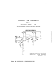


![Powermate P-WLE-1639-[E] User's Manual](http://vs1.manualzilla.com/store/data/006990483_1-9a9892bf0fafc5b84d77a1712d729228-150x150.png)