1
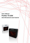
user’s manual
Scantech Nexus N-3030
Bar code laser scanner
User’s Manual
Scantech Nexus N-3030
Copyright © 2003, Scantech-ID BV.
This manual is copyrighted, with all rights reserved. Under the copyright laws, this manual may not, in
whole or in part, be copied, photocopied, reproduced, translated or converted to any electronic medium or
machine readable form without prior written consent of Scantech-ID BV.
Limited Warranty
Under all circumstances this manual should be read attentively, before installing and/or using the pro-duct.
In no event shall Scantech-ID BV be liable for any direct, indirect, special, consequential or incidental
damages arising out of the use or inability to use this documentation or product, even if advised of the
possibility of such damages. In particular, Scantech-ID BV shall not be liable for any hardware, software, or
data that is stored or used with the product, including the cost of repairing, replacing or recovering the
above. Scantech-ID BV reserves the right to change parts of the device at any time without preceding or
direct announcement to the client.
Scantech-ID BV reserves the right to revise this manual, and to make changes in the contents without
obligation to notify any person or entity of the revision or change. A serial number appears on the product.
Make sure that this official registration number has not been removed. It should be used whenever
servicing by Scantech-ID BV or an authorized Scantech dealer is necessary.
Important
This equipment has been tested and found to comply with the limits for a Class B digital device, pursuant to
EN55022, and with the limits for a class A digital device, pursuant to part 15 of the FCC rules. These limits
are designed to provide reasonable protection against harmful interference when the equipment is operated
in a commercial environment. This equipment generates, uses, and can radiate radio frequency energy
and, if not installed and used in accordance with the user’s manual, may cause harmful interference to radio
communications. Operation of the equipment in a residential area is likely to cause harmful interference in
which case the user will be required to correct the interference at his own expense. Any unauthorized
changes or modifications to this equipment could void the user’s authority to operate this equipment.
For CE-countries:
- The Nexus is in conformity with the CE standards. Please note that a Scantech CE-marked power supply
unit should be used to conform to these standards.
For USA & Canada
- To be used with UL listed and CSA certified computers/POS systems.
- A utiliser avec des ordinateurs/systèmes POS registrés UL/certifiés CSA.
- This scanner should only be powered by a UL listed or CUL Certified Power Supply having limited power
source of Class 2 outputs, rated +5.2 Vdc / minimum 0,64 A, minimum 40 °C or the scanner should be
directly powered by a UL listed and CSA certified computer/POS system, having limited power source
of Class 2 outputs, rated 8 Vdc to 16 Vdc / minimum 0,55 A, minimum 40 °C.
Radio and television interference
Operation of this equipment in a residential area can cause interference with radio or television reception.
This can be determined by turning the equipment off and on. The user is encouraged to try to correct the
interference by one or more of the following measures:
• Re-orientate the receiving antenna
• Relocate the devices with respect to the receiver
• Move the device away from the receiver
• Plug the device into a different outlet in order to have the device and receiver on
different branch circuits
If necessary, the user should consult the manufacturer, an authorized Scantech dealer or experienced
radio/television technician for additional suggestions. The booklet "How to Identify and Resolve Radio-TV
Interference Problems", prepared by the Federal Communications Commission, can be of help. It can be
obtained from the U.S. Government Printing Office, Washington, DC 20402, Stock No. 004000003454.
P/N A1020014 November 2003
Table of contents
Preface
...................................................................................................i
1.1 Unpacking the Nexus N-3030................................................. 2
1.2 Scanning bar codes with the Nexus N-3030 ............................ 4
1.3 Scanner labelling .................................................................. 5
1.4 Maintaining the scanner......................................................... 8
1.5 Controlling the scanner from the POS system ......................... 9
2.1 Connecting the scanner....................................................... 12
2.2 Installing the scanner on a counter surface ........................... 14
2.3 Installing the scanner using the flexible scanner stand............ 16
2.4 Removing the scanner from the end cover ............................ 20
Appendices ............................................................................................... 21
A
Connector types and pin definitions ...................................... 22
B
Technical specifications....................................................... 25
C
Troubleshooting.................................................................. 27
Preface
The Nexus N-3030 is a new presentation laser scanner which allows handsfree
bar code scanning, based on proven Scantech-ID technologies which form the
basis of all our omni-directional scanners. Bar code labels are read by
presenting the labels towards the scanner. Scanning labels with the Nexus N3030 hardly requires any arm movement. As a result only little free space on the
counter top is necessary.
The Nexus can either be fixed on a counter surface or on a flexible stand. The
flexible stand allows you to direct the scan pattern in a way that is optimal for
your application.
The Nexus N-3030 reads all popular bar code symbologies. An important
feature of the Nexus N-3030 is its programmable sleep mode. If the scanner is
not used within a programmable period of time, the scanner switches off
automatically. The scanner can be re-activated by pressing the switch on top of
the scanner.
The Nexus N-3030 is available in two versions. Each version features a specific
multiple interface for communication with the host system. The multiple interface
versions are: RS232C/OCIA and IBM RS485/Keyboard Wedge/USB versions.
This manual contains two chapters and three appendices. The first chapter
describes the Nexus and its general features. The description for installation can
be found in the second chapter. Precisely follow the instructions for the
installation of the scanner. Default settings can be changed with the bar code
labels from the Configuration Guide that came with the scanner.
Appendix A gives the pin definition for the Data ports of the scanner. The pin
definition may be required when you want to make a new cable for
communication with the POS/computer. Technical specifications of the Nexus N3030 can be found in Appendix B. Refer to Appendix C for troubleshooting if the
scanner is not working properly.
Chapter 1 The Nexus N-3030
The Nexus N-3030
2
1.1
UNPACKING THE NEXUS N-3030
Remove the scanner and its accessories from the box and packing material.
Refer to the packing list to make sure you have received all the items ordered.
Visually inspect the scanner and accessories for any evidence of physical
damage. Refer to the upper figure on page 5 to locate the interface label and
make sure that the scanner interface corresponds with the host system
interface. Immediately contact your supplier if anything appears to be damaged,
or if the supported interface does not correspond with the host system
interface.
The Nexus N-3030
3
The specific parts of the Nexus N-3030 are:
Sleep mode button
-
When a sleep mode time-out is programmed,
the scanner can be re-activated by pressing this
switch. The sleep mode feature is
programmable with the menu labels from the
Configuration guide.
NOTE:
The default value for the sleep
mode time-out is set to 30 minutes. When the
scanner is in sleep mode, the LED is
intermittently flashing red.
LED
-
A red LED indicates that the scanner is ready to
read a bar code. A green LED indicates a good
read.
Good read buzzer
-
The buzzer is heard whenever data has been
read correctly. The frequency and volume can
be adjusted
Optional parts & accessories:
Flexible scanner
stand
-
The rotary and flexible stand allows you to
direct the scan pattern in a way that is optimal
for your application (a mounting kit with screws
and tapes is included).
End cover
-
This part serves to fix the scanner to the
counter or to the stand.
Interface cable
-
One of various types of cable to connect to
your host computer / POS system.
Power supply
-
If your scanner is not directly powered
(optional)
Mains cable
-
To connect your power supply (optional)
User’s manual
-
This manual in print
Configuration guide
-
Booklet containing barcodes for configuration
of your scanner
The Nexus N-3030
4
1.2
SCANNING BAR CODES WITH THE NEXUS N-3030
The Nexus N-3030 is an omni-directional presentation scanner featuring a 7
directional scan field with a 24 lines scan pattern. Bar code labels can easily be
read by presenting them to the scanner.
The scanner's scan volume is illustrated in the figure below. The optimal reading
zone lies between 2 and 15 cm from the scanner window, but bar codes can be
read up to 30 cm (11.8 in.) from the scanner window.
If a scanner with flexible stand is purchased, the stand allows you to direct the
optimal reading zone in a way that suits your application most.
Scanning a bar code label with a presentation scanner is very simple: present
the product’s bar code label to the scanner as illustrated in the figure below.
1
2
The Nexus N-3030
1.3
5
SCANNER LABELLING
Two labels are present on the housing of the Nexus N-3030 as indicated in the
figure below (for IBM validated scanners these two labels are also present at the
exterior of the scanner). Two labels are also visible through the scanner window.
All labels are attached by the manufacturer and should not be removed.
Scantech-ID BV
Amersfoortsestr. 124 3769 AN
Soesterberg
Netherlands
The scanner’s serial number is found underneath the bar code label as depicted
in the figure above. This official registration number is strictly related to the
device. The supplier may ask for this number when the scanner needs servicing.
The Nexus N-3030
6
Laser safety
German:
Der Strichcode-Scanner N-3030 entspricht den Sicherheitsvorschriften nach IEC 825-1 (1993) für ein
Laserprodukt der Klasse I. Er entspricht auch U.S. 21CFR1040, anwendbar auf ein Laserprodukt der
Klasse IIa. Vermeiden Sie langzeitiges Hineinblicken in direktes Laserlicht.
Dutch:
De N-3030 scanner voldoet aan de veiligheidsnormen IEC 825-1 (1993) voor een Klasse I
laserproduct. Tevens voldoet de scanner aan U.S. 21CFR1040, van toepassing op een Klasse IIa
laserproduct. Vermijd langdurig kijken in direct laserlicht.
French:
Le scanner N-3030 est conforme aux normes de sécurité IEC 825-1 (1993) s’appliquant à un produit
laser de la classe I. Il est également conforme à la U.S. 21CFR1040 telle qu’elle s’applique à un
produit laser de la classe IIa. Eviter de rester exposé longtemps à la lumière directe du laser.
Danish:
N-3030 skanneren er i overensstemmelse med sikkerhedsstandarden IEC 825-1 (1993) for
laserprodukter i klasse I. Den er også i overensstemmelse med U.S. 21CFR1040, der gælder for
laserprodukter i klasse IIa. Undgå at se direkte på laserlys i længere perioder.
Finnish:
N-3030-skanneri täyttää luokan I lasertuotteelle IEC 825-1:ssä (1993) asetetut turvavaatimukset. Se
täyttää myös U.S. 21CFR1040:ssa asetetut vaatimukset siltä osin kuin ne koskevat luokan IIa
lasertuotetta. Vältä pitkäaikaista suoraan laservaloon katsomista.
Swedish:
Avsökaren N-3030 uppfyller säkerhetsnormen IEC 825-1 (1993) för laserprodukter av klass 1. Den
uppfyller dessutom U.S. 21CFR1040 som gäller för laserprodukter av klass IIa. Undvik att titta i
direkt laserljus under längre perioder.
Norwegian:
N-3030 skanneren er i samsvar med sikkerhetsstandarden IEC 825-1 (1993) for laserprodukter i
klasse I. Den er også i samvar med U.S. 21CFR1040 for laserprodukter i klasse IIa. Unngå å se
langvarig på direkte laserlys.
Italian:
Lo scanner N-3030 è conforme alle norme di sicurezza IEC 825-1 (1993) relative ad un prodotto
laser di Classe 1. È inoltre conforme alla norma U.S. 21CFR1040 relativa ad un prodotto laser di
Classe IIa. Evitare l'esposizione prolungata all'emissione diretta di luce laser.
Portuguese:
O scanner N-3030 está conforme as normas de segurança IEC 825-1 (1993) para a Classe 1 dos
produtos laser. Também está conforme a norma U.S. 21CFR1040 aplicada nos produtos laser da
Classe IIa. Evite expor os olhos directa e prolongadamente aos raios laser.
The Nexus N-3030
7
Spanish:
El scanner N-3030 reune las normas de seguridad IEC 825-1 (1993) para un producto laser de
Clase 1. Y también reune las normas U.S. 21CFR1040 que se aplican a un producto laser de Clase
IIa. Se debe evitar mirar muy fijo en luz lasérica directa.
English:
The N-3030 scanner complies with safety standard IEC 825-1 (1993) for a Class I laser product. It
also complies with U.S. 21CFR1040 as applicable to a Class IIa laser product. Avoid long term
viewing of direct laser light.
Optical:
The use of optical instruments with this product will increase eye hazard. Optical instruments include
binoculars, microscopes and magnifying glasses but do not include eye glasses worn by the user.
Radiant Energy:
The N-3030 uses a low-power laser diode operating at 630…670 nm in an opto-mechanical scanner
resulting in less than 0.6 mW peak output power. Laser light observed at 13 cm (5.1 in.) above the
window through a 7 mm (0.28 in.) aperture and averaged over 1000 seconds is less than 3.9 µW
per CDRH Class IIa specification. Do not attempt to remove the protective housing of the scanner,
as unscanned laser light with a peak output up to 0.8 mW could be accessible inside.
Laser Light Viewer:
The scanner window is the only aperture through which laser light may be observed on this product.
A failure of the scanner motor, while the laser diode continues to emit a laser beam, may cause
emission levels to exceed those for safe operation. The scanner has safeguards to prevent this
occurrence. If, however, a stationary laser beam is emitted, the failing scanner should be
disconnected from its power source immediately.
Adjustments:
Do not attempt any adjustments to or alteration of this product. Do not remove the scanner’s
protective housing. There are no user-serviceable parts inside.
CAUTION: Use of controls or adjustments or performance of procedures
other than those specified herein may result in hazardous laser light
exposure.
The Nexus N-3030
8
1.4
MAINTAINING THE SCANNER
The Nexus N-3030 scanner requires little maintenance. Only occasional cleaning
of the scanner window is necessary to remove dirt and fingerprints. Cleaning
can be performed during operation with a non-abrasive glass spray cleaner and
a soft lint-free cloth.
The Nexus N-3030
1.5
9
CONTROLLING THE SCANNER FROM THE POS
SYSTEM
The Nexus N-3030 can be controlled from the POS system via the RS232C
interface. Control is achieved by transmitting the following single byte
commands to the scanner. In the Scantech default setting the following
commands are available (more details upon request):
ASCII code
05 Hex
OE Hex
OF Hex
12 Hex
14 Hex
Function
power-up re-initialization
enable (cancels disable)
Disable
sleep
wake (cancels sleep)
byte is also called:
ENQ or <Ctrl-E>
Shift Out or <Ctrl-N>
Shift In or <Ctrl-O>
DC2 or <Ctrl-R>
DC4 or <Ctrl-T>
When the scanner is disabled, the motor of the scanner will stay on until the
scanner goes into sleep mode.
Chapter 2 Installing the Nexus N-3030
Installing the Nexus N-3030
12
Depending on the way you want to use the Nexus N-3030, the scanner can be
installed in two different ways: fixed on a counter surface or on a flexible stand.
Instructions for installation on a counter surface are given in Section 2.1.
Instructions for installation on the flexible stand are given in Section 2.2.
Due to many POS systems on the market, a large number of communication
cables is available. Make sure that you have the right cable to connect the
scanner to your POS or computer.
NOTE
The scanner and the host system must be switched off before
starting the installation of the scanner. By following this precaution
you prevent any electrical damage.
You are advised to install the scanner in an air circulated place out
of direct sunlight
2.1
CONNECTING THE SCANNER
Before you connect any cables to the scanner, check whether you should guide
them through the foot or counter surface!
The Nexus N-3030 is available in two different interface versions:
Dual interface: RS232 and OCIA
Triple interface: RS485, Keyboard Wedge (KBW) and USB/USB plus power.
Each version also provides:
Auxiliary port for additional scanner
EAS connector
Power connector
If you use “direct powering”, power is supplied by the host and you do not need
to connect an external power supply to the Power Input entry.
Installing the Nexus N-3030
13
Use the illustration below to see where to connect your cable(s) to the scanner.
Check whether you have to use Port 1 or Port 2 for your type of data-interface.
Before closing the end cover later on (see mounting instructions in chapter 2.2
and 2.3) guide the cables through the scanner as shown in the illustration below.
Installing the Nexus N-3030
14
IMPORTANT
If the host system is an IBM 4683/4684 POS, the scanner with
IBM RS-485 interface should be connected to PORT 17 of the
host only.
If the host system is an IBM 4693/4694 POS, the scanner with
IBM RS-485 interface should be connected to PORT 9E of the
host only.
2.2
INSTALLING THE SCANNER ON A COUNTER SURFACE
To install the scanner without the flexible scanner stand, follow the instructions
below.
1.
Remove the two rubber feet from the end cover. Lead the communication
cable and power supply cable through the slit. Fasten the end cover to the
surface with two screws as illustrated in the figure.
NOTE
You can use the end cover as a template to mark the places for
the mounting holes at the counter surface and drill two holes.
If you do not want to drill holes in the counter top, the scanner
can be installed without fixing it to the surface. In this case the
rubber feet will prevent the scanner from sliding.
Installing the Nexus N-3030
15
2.
Position the scanner as indicated in the figure below and rotate the scanner
around the cover. Make sure that connectors and cables are placed as
indicated in the figures, to allow easy attachment of the scanner to the end
cover. Press the scanner until a "click" is heard.
3.
Plug the remote ends of all cables into the appropriate connections of your
host POS-system.
4.
If you are using an external power supply, power on the scanner by
connecting the IEC power cord to the AC/DC power supply and plugging the
AC power cord into an AC power outlet. Switch on the host system.
IMPORTANT
To activate Data port 2 (OCIA or KBW interface) scan the following
codes from the Configuration Guide:
1. open the scanner Programming Mode by scanning code 1.1
2. return to factory default settings by scanning code 1.3
Once the scanner is installed, you can start scanning bar code labels. If you
want to change the default settings of the scanner, proceed to the Configuration
Guide which came with the scanner.
Installing the Nexus N-3030
16
2.3
INSTALLING THE SCANNER USING THE FLEXIBLE
SCANNER STAND
To install the scanner on the flexible scanner stand, lead the cables through the
stand to be connected to the scanner. Furthermore the stand should be
fastened to the counter top. Finally, the scanner should be fastened to the
stand.
You are advised to precisely follow the next steps:
1.
Remove the cover disk (center cap) from the stand and remove the bottom
plate from the stand.
2.
Place the bottom plate on the counter and mark the places for the mounting
holes on the counter top and mark the hole to lead the cables through.
3.
Drill the mounting holes and the lead-through hole.
NOTE
If you prefer not to drill in your counter, you can mount the stand
using the provided double-sided tape and have the cables leave the
foot at the rear, just above the circular basis.
4.
Fix the bottom plate on the counter top using the screws or tape from the
mounting kit.
5.
Lead the cables from the bottom upwards through the hole in the counter,
through the bottom plate and through the scanner stand.
Installing the Nexus N-3030
17
6.
Click the stand on the bottom plate.
7.
Connect the cables to the scanner. Refer (for the data cable in particular) to
chapter 2.1 for the correct connections.
8.
Place the scanner onto the flexible stand and rotate the scanner as
indicated in the figure. Make sure that connectors and cables are properly
placed to allow easy attachment. Press the scanner until a "click" is heard.
Installing the Nexus N-3030
18
9.
Click the cover disk on the foot of the stand.
10. Connect the data cable to the host.
(For IBM POS systems, see note in chapter 2.1)
11. Place the scanner in the desired angle.
In case you have an external power supply, connect the IEC power cord to
the AC/DC power supply and plug the AC power cord into an AC power
outlet.
12. Switch on the host system
IMPORTANT
To activate Data port 2 (OCIA or KBW interface) scan the
following codes from the Configuration Guide:
1. open the scanner Programming Mode by scanning code 1.1
2. return to factory default settings by scanning code 1.3
Installing the Nexus N-3030
19
Once the scanner is installed, you can start scanning bar code labels. If you
want to change the default settings of the scanner, proceed to the Configuration
Guide which came with the scanner.
Installing the Nexus N-3030
20
2.4
REMOVING THE SCANNER FROM THE END COVER
To remove the scanner from the end cover, that is either attached on the
counter or on the scanner stand:
1.
Locate the small hole at the end cover of the scanner.
2.
Remove the end cover by pressing it with the tip of a stick as indicated in
the figure.
Appendices
A. Connector types and pin definitions
B. Technical Specifications
C. Troubleshooting
Appendices
22
A
CONNECTOR TYPES AND PIN DEFINITIONS
There are two multiple interface versions of the Nexus available: RS232C/OCIA
and IBM RS485/Keyboard Wedge/USB. The various pin definitions for the
applicable Data port are given on page 20 and 21. The connector to be used for
the port is indicated below.
IMPORTANT
To activate Data port 2 (OCIA or KBW interface), follow this
sequence:
1. Plug in the appropriate interface cable and then power up the
scanner.
2. Scan the following codes from the Configuration Guide:
- Open the scanner Programming Mode by scanning code 1.1
- Return to factory default settings by scanning code 1.3
Appendices
23
Pin definition for dual interface version RS232C / OCIA
Pin
1
2
3
4
5
6
7
8
R232C interface
Data port 1
Description Direction
CTS
input
RXD
input
TXD
output
RTS
output
GND
DC-power
input
Do not
(reserved)
connect
Do not
(reserved)
connect
Pin
1
2
3
4
5
6
OCIA interface
Data port 2
Description Direction
IFID 1
input
DATA
output
DATA-RTN
output
CLK-IN
input
GND
CLK-IN-RTN
input
7
RESET
input
8
RESET-RTN
input
Note: Connect pin 1 to 3
Pin definition for triple interface version RS485 / KBW / USB
Pin
1
RS485 interface
Data port 1
Description
Direction
Do not
connect
Pin
1
USB interface
Data port 1
Description Direction
D+
Do not
connect
Do not
connect
input/output
2
IO-A
input/output
2
3
IO-B
input/output
3
-
4
D-
input/output
input
5
6
Input 8-16V
(reserved)
7
GND
DC-POWER
Do not
connect
(reserved)
8
IFID2
input
4
5
6
7
8
Do not
connect
GND
DC-POWER
Do not
connect
Do not
connect
-
(reserved)
Note: for standard USB connection
(with additional power supply)
connect pin 6 to pin 8 only.
Appendices
24
KBW interface
Data port 2
Pin
Description Direction
1
IFID 1
input
2
KB-DATA
output
3
KB-CLK
output
4
PC-DATA
input
5
PC-GND
6
PC-CLK
input
7
PC-5V
input
8
IFID 2
input
Note: connect pin 1 to 8
Pin definition for all scanner versions:
Pin
1
2
3
4
AUX
Port Aux
Description Direction
+5 VDC
output
CTS
input
RXD
input
(reserved)
-
5
RTS
output
6
7
8
9
10
GND
(reserved)
(reserved)
(reserved)
(reserved)
-
EAS
Pin
1
2
Description
(-)
(+)
Direction
-
POWER
Pin
1
2
Description
GND
(+)
Direction
input
Appendices
B
25
TECHNICAL SPECIFICATIONS
Electrical
Power supply voltage
DC input to scanner
Interfaces
100 – 240 V ac 50/60 Hz (adapter)
5.2 V dc 450 mA (at dc-jack) or
8 – 16 V dc 3 Watt (direct power)
Depending on scanner version:
RS232 and OCIA or
RS485, KBW and USB/USB plus power
Optical
Light source
Depth of field
Scan pattern
Scan rate
Visible laser diode (630 - 670 nm)
300 mm
7 directions scan field, 24 lines scan pattern
2480 scans / second
Decoding
Bar code types
EAN/UPC/JAN + Add-on, code 32 (Ital. Pharmacode)
Code 128, EAN 128, Code 39 (+ full ASCII), Codabar,
Interleaved 2/5
Physical
Weight
Weight with stand
Dimensions
Dimensions with stand
500 g
675 g
HxWxD :
:
HxWxD :
:
146 x 135 x 61 mm
5.75 x 5.35 x 2.40 inch
215-237 x 135 x 135 mm
8.47 – 9.34 x 5.35 x 5.31 inch
Appendices
26
Environmental
Operating temperature
Humidity
0° C ~ 40° C
20% ~ 95% RH (non-condensing)
Safety
Laser safety
Electrical safety
Flammability rate
IEC 825-1 (1993) Class I, U.S. CDRH: 21CFR1040
Class II a
EN 60950 second edition
UL1950, c-UL (according CSA22.2.950)
94V-0
EM Compatibility
Radio and TV interference
Harmonic current emissions
EM-immunity
EN 55022 Class B (1998) + A1 (2000), FCC part 15
Class A (1992)
EN 61000-3-2 (1995) + A1 (1998) + A2 (1998)
EMC Directive 89/336/EEC
EN 55024 (1998) + A1 (2001)
Appendices
C
27
TROUBLESHOOTING
This section contains information on solving problems you may encounter when
using the scanner. If troubles occur, take a moment to read the information in
this section. However, before referring to the diagnostic tips make sure that the
scanner is installed as described in Chapter 2 and that all cables are properly
connected.
Problem
The scanner is on but a bar code
cannot be read. The LED is red.
The scanner is on, but the motor is not
rotating. A bar code cannot be read.
The LED is intermittently flashing red.
The LED is alternating red/green
The LED is alternating red/green and
beeps are heard.
The scanner does not accept more
than two or three bar codes
Diagnostic Tips
The scanner window is dirty. Clean
the scanner window as described in
the Maintenance section.
The presented bar code type is not
enabled. Select the bar code type
with the Configuration Guide.
The scanner is disabled by the host.
Refer to Section 1.5.
The bar code type you presented to
the scanner is not supported by the
Nexus.
The scanner is in sleep mode. Press
the switch on top of the scanner to
reactivate the scanner (or use the
wake protocol. Refer to section
1.5).
Mirror motor is defective and must
be replaced (Authorized personnel
only).
Possible failure of the scanning
safeguard circuit. Immediately
disconnect the scanner from its
power source. Contact your
supplier.
There is no proper handshaking with
the host system. Switch the host
system on and check connection
and communication settings.
28
Problem
The LED is orange.
The LED is blinking orange.
The LED remains green
A bar code is read by the scanner but
not accepted by the host system.
Appendices
Diagnostic Tips
The laser is not functioning. The
laser is defective. Contact your
supplier.
The ambient temperature is too
high. Make sure the scanner has
enough air ventilation and is not
placed in direct sunlight.
The scanner is continuously seeing
a bar code. Remove all bar code
labels from the scan volume of the
scanner and try again.
The scanner cannot send the data
to the host system. There is no
proper handshaking between the
scanner and the host. Scanner
buffer is full. Make sure that all
cables are connected and your host
system is ready to receive data.
The communication cable is not
connected to the serial port of your
host system. Refer to the manual of
your host system to locate the serial
port.
The communication settings of the
host and scanner do not match.
Ensure that the setting value for
both devices are the same. For
proper adjustment values see the
Configuration Guide.
The communication cable does not
suit your host system. Contact your
supplier for the correct
communication cable.
The data format is not supported by
the software running on the host
system.
Appendices
Problem
USB is not working
29
Diagnostic Tips
Unless you use USB plus power, you
need a separate power connection
to the scanner like the external
power supply.
Restart the scanner by temporarily
disconnecting the power. This may
help the POS system to detect the
scanner. The very first time the PC
might install some general drivers,
possibly from your computer setup
CD.
In case of KB emulation you can
select various ‘keyboard languages’
or the universal ‘Alt-input-method’.
In a windows environment verify with
the device manager that a HID
(Human Interface Device) is installed
for the scanner.
Check that scanner and POS-system
or Computer both expect the same
USB protocol (KB emulation, RS-232
emulation or IBM POS protocol).
See Configuration Manual for setup
codes and reset (re-power) the
scanner after making any changes.
Scantech-ID BV
Amersfoortsestraat 124
3769 AN Soesterberg
The Netherlands
Phone:
Fax:
E-mail:
Internet:
+31 (0)33 469 84 00
+31 (0)33 465 06 15
[email protected]
www.scantech-id.com