1
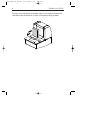
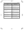
Scant9802_dl1_lp.qxd
03-11-2000 11:06
Pagina a
User's manual
Intermec MaxiScan 2500 DP
Scant9802_dl1_lp.qxd
03-11-2000 11:06
Pagina b
Regulatory Statements
CE
Intermec hereby declares that the MaxiScan 2500 DP has been tested and found compliant with
the below listed standards as required by the EMC Directive 89/336EEC as amended by 92/31/EEC
and by the Low Voltage Directive 73/23/EEC as amended by 93/68/EEC:
EN 55022 (1992)
EN 50082 (1998)
EN 60950 (1993)
USA: This device complies with Part 15 of the FCC Rules. Operation is subject to the following two
conditions: (1) this device may not cause harmful interference, and (2) this device must accept any
interference received, including interference that may cause undesired operation.
This equipment has been tested and found to comply with the limits for a Class B digital device,
pursuant to part 15 of the FCC Rules. It generates, uses and can radiate radio frequency energy. If not
installed and used in accordance with the instructions, it may cause interference to radio
communications. If this equipment causes interference, the user will be required to correct the
interference at the user’s own expense.
This equipment complies with the UL 1950 standard.
Canada: This Class B digital apparatus meets all requirements of the Canadian Interference Causing
Equipment Regulations.
Cet appareil numerique de la classe B respect toutes les exigences du Reglement sur le materiel
brouilleur du Canada.
This equipment complies with the UL 1950 standard.
Cet equipment ext conforme a la norme UL 1950.
Mexico: Este equipo cumple con la certification NOM.
Australia –New Zealand: This equipment has been tested and found to conform to the Australian EMC
framework concerning Class B digital devices, prescribed by the Australian and New-Zealand standard
AS/NZS 3548.
The information contained in this document is for informational purposes only and is subject to change
without notice. No part of this document may be copied or reproduced in any manner without the prior
written permission of Intermec Technologies Corporation.
The word Intermec, the Intermec logo, Scanplus and EasySet are either trademarks or registered
trademarks of Intermec.
Throughout this document, trademarked names may be used. Rather than put a trademark (tm or R)
symbol in every occurrence of a trademarked name, we state that we are using the names only in an
editorial fashion, an do the benefit of the trademark owner, with no intention of infringement.
P/N 3-453049-01 October
Scant9802_dl1_lp.qxd
03-11-2000 11:06
Pagina c
Table of contents
Preface
Chapter 1
Chapter 2
Appendices
i
The MaxiScan 2500 DP
1
1.1 Unpacking the MaxiScan 2500 DP
1.2 Scanning bar codes with the MaxiScan 2500 DP
1.3 Scanner labelling
1.4 Maintaining the scanner
1.5 Changing the scanner windows
1.6 Controlling the scanner from the POS system
2
4
7
10
11
12
Installing the MaxiScan 2500 DP
13
Installing the scanner into a counter surface
14
A. Connector types and pin definitions
20
B. Technical specifications
22
C. Troubleshooting
23
Scant9802_dl1_lp.qxd
03-11-2000 11:06
Pagina d
Preface
The MaxiScan 2500 DP is an innovative high-performance Bi-optic scanning
solution to provide hypermarket and supermarket retailers with the outstanding
benefits of dual plane scanning. Ergonomically designed for retailers with small
counter space but a high throughput, the scanner provides exceptional scanning
capabilities from any direction, including from the top - improving speed at
checkout and reducing operator fatigue.
The MaxiScan 2500 DP is also ideally suited for a range of retailers including:
pharmacies, department stores, petrol stations, convenience stores,
newsagents and drugstores.
With an exceptionally small footprint the MaxiScan is less than 11 cm deep incounter and 22cm wide, giving maximum room for peripherals such as cash
drawers - as well as providing extra space under the counter for the cashiers
legs. The scanner also features a stainless steel sapphire top deck as standard
with a rubber suspension system for maximum durability. This manual contains
two chapters and three appendices. The first chapter describes the MaxiScan
2500 DP scanner, its general features as well as the way in which it can be
used. The precise instructions for installing the scanner are listed in the second
chapter. Default settings can be changed using the bar code labels in the
Configuration Guide supplied with the scanner. Appendix A shows all connectors
of the scanner. Technical specifications of the MaxiScan can be found in
Appendix B. Refer to Appendix C for troubleshooting if the scanner is not
working properly.
Scant9802_dl1_lp.qxd
03-11-2000 11:06
Pagina e
Chapter 1
The MaxiScan 2500 DP
Scant9802_dl1_lp.qxd
03-11-2000 11:06
Pagina 2
2
1.1
The MaxiScan 2500 DP
UNPACKING THE MAXISCAN 2500 DP
Take the scanner and its accessories out of the box and remove all packing
materials. Refer to the packing list in order to ensure that you have received all
the items ordered. Visually inspect the scanner and accessories for any visible
traces of damage. Refer to the figure on page 7 to locate the interface label and
verify if the scanner interface corresponds with the host system interface.
Immediately contact your supplier if anything appears to be damaged, or if the
supported interface does not correspond with the host system interface.
Good read
speaker
LED
Sleep mode switch
Product flow
indicators
Top deck
Scant9802_dl1_lp.qxd
03-11-2000 11:06
Pagina 3
The MaxiScan 2500 DP
3
The various parts of the MaxiScan 2500 DP are:
Sleep mode switch
If a sleep mode time-out has been programmed, the
scanner can be reactivated by pressing this switch.
The sleep-mode feature can be programmed by
means of the menu labels in the Configuration Guide.
NOTE: The default value for the sleep mode time-out
is set to 30 minutes. When the scanner is in
sleep mode, the LED is intermittently flashing
red.
LED
A red LED indicates that the scanner is ready to read
a bar code. A green LED indicates a good read.
Good read speaker
The speaker sounds whenever data has been
correctly read. Both frequency and volume can be
adjusted by means of the menu labels from the
Configuration Guide.
Top deck
The top deck, or horizontal scanner window can be
changed for a different type. Just sligthly lift the deck
at the front side and pull it towards you.
Product flow indicators The product flow indicators (two embossed arrows on
the stainless-steel top deck frame) indicate the
direction in which the products must be passed along
the scanner windows.
Scant9802_dl1_lp.qxd
03-11-2000 11:06
Pagina 4
4
1.2
The MaxiScan 2500 DP
SCANNING BAR CODES WITH THE MAXISCAN 2500 DP
Sweet spot
Scan volume
The MaxiScan 2500 DP is an omnidirectional scanner featuring a 14-directional
scan field with a 28-lines scan pattern. Its scan volume is illustrated by the
larger light-coloured cube in the figure above. The optimal reading zone is
indicated by the smaller dark-coloured cube, the so-called ‘sweet spot’.
Scant9802_dl1_lp.qxd
03-11-2000 11:06
The MaxiScan 2500 DP
Pagina 5
5
It does not matter how you present the product to the scanner. The scanner will
read the bar code in any position and from any direction, for example:
Scanning a bar code label in fly-by mode is simply done by passing the bar code
label on the product along the scanner as illustrated in the figure below. You can
either pass the product from left to right or vice versa.
Scant9802_dl1_lp.qxd
6
03-11-2000 11:06
Pagina 6
The MaxiScan 2500 DP
Scanning a bar code label in presentation mode is also simple: present the bar
code label on the product to the scanner as illustrated in the figure below.
Scant9802_dl1_lp.qxd
03-11-2000 11:06
Pagina 7
The MaxiScan 2500 DP
1.3
7
SCANNER LABELLING
There are five labels on the scanner. The first three labels can be found on the
housing of the MaxiScan 2500 DP, as indicated in the figure below. The
remaining two labels are visible through the scanner window.
All the labels have been attached by the manufacturer and should in no case be
removed.
- - - - - - - - - - - - - - - - - - - - - - - - - - - - - - - - -
World wide
Patents Pending
12V....
600mA
U
R
-12V.... 5V....
25mA
L
ACCESORY
4F10
I.T.E.
Part No: <partnr>
350mA
LISTED
U
R
L
C
Software
<software number>
WO1:<workordernr.>
R
R
Serial no. 1
<serial number>
AUX. INTERFACE
PORT 2
model <model>
Manufactured
Port1 <IF type>
<date>
Port2 <IF type>
INTERFACE POWER
PORT 1
The scanner’s serial number can be found under the bar code label, as
depicted in the figure above. This official registration number is strictly related
to the device. The supplier may ask for this number when the scanner needs
servicing.
IEC825 class
1 laser product
Complies with 21CFR1040 as
applicable to a class IIa laser
product. Avoid long term viewing
of direct laser light
CAUTION-Laser light when open
Do not stare into beam
Scant9802_dl1_lp.qxd
8
03-11-2000 11:06
Pagina 8
The MaxiScan 2500 DP
Laser safety
English:
The M2500 DP scanner complies with safety standard IEC 825-1 (1993) for a
Class 1 laser product. It also complies with U.S. 21CFR1040 as applicable to a
Class IIa laser product. Avoid long term viewing of direct laser light.
German:
Der Strichcode-Scanner M2500 DP entspricht den Sicherheitsvorschriften nach
IEC 825-1 (1993) für ein Laserprodukt der Klasse 1. Er entspricht auch U.S.
21CFR1040, anwendbar auf ein Laserprodukt der Klasse IIa. Vermeiden Sie
langzeitiges Hineinblicken in direktes Laserlicht.
Dutch:
De M2500 DP scanner voldoet aan de veiligheidsnormen IEC 825-1 (1993) voor
een Klasse 1 laserprodukt. Tevens voldoet de scanner aan U.S. 21CFR1040,
van toepassing op een Klasse IIa laserprodukt. Vermijd langdurig kijken in direkt
laserlicht.
French:
Le scanner M2500 DP est conforme aux normes de sécurité IEC 825-1 (1993)
s’appliquant à un produit laser de la classe 1. Il est également conforme à la
U.S. 21CFR1040 telle qu’elle s’applique à un produit laser de la classe IIa. Eviter
de rester exposé longtemps à la lumière directe du laser.
Danish:
M2500 DP skanneren er i overensstemmelse med sikkerhedsstandarden IEC
825-1 (1993) for laserprodukter i klasse 1. Den er også i overensstemmelse
med U.S. 21CFR1040, der gælder for laserprodukter i klasse IIa. Undgå at se
direkte på laserlys i længere perioder.
Finnish:
M2500 DP-skanneri täyttää luokan 1 lasertuotteelle IEC 825-1:ssä (1993)
asetetut turvavaatimukset. Se täyttää myös U.S. 21CFR1040:ssa asetetut
vaatimukset siltä osin kuin ne koskevat luokan IIa lasertuotetta. Vältä
pitkäaikaista suoraan laservaloon katsomista.
Swedish:
Avsökaren M2500 DP uppfyller säkerhetsnormen IEC 825-1 (1993)
för laserprodukter av klass 1. Den uppfyller dessutom U.S. 21CFR1040 som
gäller för laserprodukter av klass IIa. Undvik att titta i direkt laserljus under
längre perioder.
Scant9802_dl1_lp.qxd
03-11-2000 11:06
Pagina 9
The MaxiScan 2500 DP
9
Norwegian:
M2500 DP skanneren er i samsvar med sikkerhetsstandarden IEC 825-1 (1993)
for laserprodukter i klasse 1. Den er også i samvar med U.S. 21CFR1040 for
laserprodukter i klasse IIa. Unngå å se langvarig på direkte laserlys.
Italian:
Lo scanner M2500 DP è conforme alle norme di sicurezza IEC 825-1 (1993)
relative ad un prodotto laser di Classe 1. È inoltre conforme alla norma U.S.
21CFR1040 relativa ad un prodotto laser di Classe IIa. Evitare l'esposizione
prolungata all'emissione diretta di luce laser.
Portuguese:
O scanner M2500 DP está conforme as normas de segurança IEC 825-1
(1993) para a Classe 1 dos produtos laser. Também está conforme a norma
U.S. 21CFR1040 aplicada nos produtos laser da Classe IIa. Evite expor os olhos
directa e prolongadamente aos raios laser.
Spanish:
El scanner M2500 DP reune las normas de seguridad IEC 825-1 (1993) para un
producto laser de Clase 1. Y también reune las normas U.S. 21CFR1040 que se
aplican a un producto laser de Clase IIa. Se debe evitar mirar muy fijo en luz
lasérica directa.
Optical: The use of optical instruments with this product will increase eye hazard. Optical instruments include binoculars, microscopes and magnifying glasses but do not include eye glasses worn by the user.
Radiant Energy: The M2500 DP uses a low-power laser diode operating at
670 nm in an opto-mechanical scanner resulting in less than 0.96 mW peak
output power. Laser light observed on or above the window through a 7 mm
(0.28 in.) aperture and averaged over 1000 seconds is less than 3.9 µW per
CDRH Class IIa specification. Do not attempt to remove the protective housing
of the scanner, as unscanned laser light with a peak output up to 1.75 mW
could be accessible inside.
Laser Light Viewer: The scanner window is the only aperture through which
laser light may be observed on this product.
A failure of the scanner motor, while the laser diode continues to emit a laser
beam, may cause emission levels to exceed those for safe operation. The
scanner has safeguards to prevent this occurrence. If, however, a stationary
laser beam is emitted, the failing scanner should be disconnected from its
power source immediately.
Scant9802_dl1_lp.qxd
03-11-2000 11:06
10
Pagina 10
The MaxiScan 2500 DP
Adjustments: Do not attempt to make any adjustments to or alteration of this
product. Do not remove the scanner’s protective housing. There are no userserviceable parts inside.
CAUTION: Use of controls or adjustments or performance of procedures
other than those specified herein may result in hazardous laser light
exposure.
1.4
MAINTAINING THE SCANNER
The MaxiScan 2500 DP scanner requires little maintenance. Only occasional
cleaning of the scanner window is necessary in order to remove dirt and
fingerprints. The scanner can be cleaned during operation. To this end use a
non-abrasive glass spray cleaner and a soft lint-free cloth only.
Scant9802_dl1_lp.qxd
03-11-2000 11:06
Pagina 11
The MaxiScan 2500 DP
1.5
11
CHANGING THE SCANNER WINDOWS
The vertical scanner window can be replaced by lifting the top of the scanner
and vertically sliding out the window (see the figure below).
1
2
The horizontal window can be taken off by holding the edges and pulling the
window up (see the figure below).
1
2
Scant9802_dl1_lp.qxd
03-11-2000 11:06
Pagina 12
12
1.6
The MaxiScan 2500 DP
CONTROLLING THE SCANNER FROM THE POS SYSTEM
The MaxiScan 2500 DP can be controlled from the POS system via the RS232C
interface. Controlling is accomplished by transmitting the following single-byte
commands to the scanner. In the Intermec default setting the following
commands are available (more details upon request):
ASCII code
function
byte is also called:
05 Hex
power-up re-initialization
ENQ or <Ctrl-E>
0E Hex
enable (cancels disable)
Shift Out or <Ctrl-N>
0F Hex
disable
Shift In or <Ctrl-O>
12 Hex
sleep
14 Hex
DC2 or <Ctrl-R>
wake (cancels sleep)
DC4 or <Ctrl-T>
When the scanner is disabled, the scanner motor of the will remain switched-on
until the scanner goes into sleep mode.
POS system
Maxiscan 2500 DP
Scanner control
+12V dc
- 12V dc
+ 5V dc
Scant9802_dl1_lp.qxd
03-11-2000 11:06
Pagina 13
Chapter 2
Installing the MaxiScan 2500 DP
Scant9802_dl1_lp.qxd
03-11-2000 11:07
Pagina 14
14
Installing the MaxiScan 2500 DP
INSTALLING THE SCANNER INTO A COUNTER SURFACE
This chapter describes the instructions and measures necessary for installing
the MaxiScan 2500 DP scanner.
Due to many POS systems on the market, a large number of communication
cables is available. Make sure that you have the right cable to connect the
scanner to your POS or computer.
NOTES
■ The scanner and the host system must be switched off before starting the
installation of the scanner. By following this precaution you prevent any
electrical damage.
■ You are advised to install the scanner in an air circulated place out of direct
sunlight.
Follow these steps carefully in order to install the scanner at an exact level with
the counter surface.
1. Locate the optimal scanner position in relation to the counter surface. Pay
attention to the product flow, the distance to the counter edge and
convenience for the operator.
2. You have two options for mounting the scanner into the counter. Either:
A) The scanner bottom is supported by a shelf
- Cut out a hole in the counter surface according to the measures
indicated in the illustration below.
- Fit a supporting shelf for the scanner following the instructions below.
290.0
108.0
221.0
Scant9802_dl1_lp.qxd
03-11-2000 11:07
Pagina 15
Installing the MaxiScan 2500 DP
15
B) The scanner rests on a cut-out edge in the counter surface
- Cut out a hole in the counter surface according to the measures
indicated in the illustration below.
- Cut out the edges according to the indicated measures.
221.0
207.0
283.0
290.0
108.0
20.0
10.0
221.0
207.0
supporting surface for Maxiscan
Ensure that the opening and the edges in the counter surface are cut out
correctly. Both scanner top deck and counter surface must be exactly at
the same level, leaving no clearances between them.
3. After cutting the hole in the counter, lead both power supply and
communication cables through the opening.
4. Plug the communication cable with the 8 pin modular jack into Data port 1 if
the host system features the RS232C or IBM RS485 interface, or into Data
port 2 if the host system features the OCIA or KBW interface. Plug the other
connector end of the cable into the appropriate serial port of your POS or
computer. Connect the Intermec universal power supply unit to the power
supply port.
Scant9802_dl1_lp.qxd
03-11-2000 11:07
16
Pagina 16
Installing the MaxiScan 2500 DP
5. To prevent possible strain, lead both power supply and communication
cables along the backside of the scanner and attach them to the cut-out slot
in the housing by means of a tie-wrap (see illustration below).
R
ground pin
EAS connector
(more details
upon request)
R
Scant9802_dl1_lp.qxd
03-11-2000 11:07
Pagina 17
Installing the MaxiScan 2500 DP
17
6. Insert the scanner into the opening (rear end first!) as depicted in the drawing
below. Ensure that both scanner and counter surface are exactly at the same
level and that there are no clearances between both parts.
7. Power on the scanner by connecting the IEC power cord to the AC/DC power
supply and plugging the AC power cord into an AC power outlet. Switch on
the host system.
IMPORTANT
■ To activate Data port 2 (OCIA or KBW interface) scan the following codes
from the Configuration Guide:
1. open the scanner Programming Mode by scanning code 1.1
2. return to factory default settings by scanning code 1.3
Once the scanner has been installed, you can start scanning bar code labels.
If you want to change the default settings of the scanner, proceed to the
Configuration Guide supplied with the scanner.
Scant9802_dl1_lp.qxd
18
03-11-2000 11:07
Pagina 18
Installing the MaxiScan 2500 DP
Scant9802_dl2_lp.qxd
02-11-2000 16:41
Pagina 1
Appendices
A. Connector types and pin definitions
B. Technical Specifications
C. Troubleshooting
Scant9802_dl2_lp.qxd
02-11-2000 16:41
Pagina 20
20
Appendices
A. CONNECTOR TYPES AND PIN DEFINITIONS
There are two dual interface versions of the MaxiScan 2500 DP available:
RS232C/OCIA and IBM RS485/Keyboard Wedge. The various pin definitions for
the applicable Data port are given on page 21. The connector to be used for the
port is indicated below.
POWER SUPPLY PORT
GROUND PIN
IINTERFACE PORT 1
AUX PORT
EAS CONNECTOR
(more details
upon request)
AMP 5-554169-1
male connector
front view:
pin 1
pin 8
pin 1
pin 8
pin 1
pin 10
Stewart 940SP301010RK2
male connector
front view:
pin 1
INTERFACE PORT 2
AMP 5-554170-1
male connector
front view:
pin 10
Aux port
Pin
Description
1
+5VDC (250 mA max.)
2
CTS
3
RXD
4
Reserved
5
RTS
6
GND
7-10
Reserved
pin 8
pin 1
pin 1
pin 8
IMPORTANT
■ To activate Data port 2 (OCIA or KBW interface) scan the following codes
from the Configuration Guide:
1. open the scanner Programming Mode by scanning code 1.1
2. return to factory default settings by scanning code 1.3
Scant9802_dl2_lp.qxd
02-11-2000 16:41
Pagina 21
Appendices
21
Pin definition for dual interface version RS232C-OCIA
RS232C interface
Data port 1
OCIA interface
Data port 2
Pin
Description
Direction
Pin
Description
Direction
1
CTS
input
1
IFID
input
2
RXD
input
2
DATA
output
3
TXD
output
3
DATA RTN
output
4
RTS
output
4
CLOCK IN
input
5
GND
-
5
GND
-
6
Not Con.
-
6
CLOCK IN RTN
input
7
RESET
input
8
RESET RTN
input
7
Reserved
8
Pin definition for dual interface version IBM RS485-Keyboard Wedge
IBM RS485 interface
Data port 1
Pin Description
KBW interface
Data port 2
Direction
Pin
Description
Direction
1
Not Con.
-
1
IFID1
input
2
IO-A
input/output
2
KB_DATA
output
3
IO-B
input/output
3
KB_CLCK
output
4
Not Con.
-
4
PC_DATA
input
5
GND
-
5
PC_GND
input
6
Not Con.
-
6
PC_CLCK
input
7
PC_5V
input
8
IFID2
input
7
8
Reserved
Scant9802_dl2_lp.qxd
02-11-2000 16:41
Pagina 22
22
Appendices
B. TECHNICAL SPECIFICATIONS
Electrical
Power supply voltage
DC input to scanner
100 - 250 V ac, 50/60 Hz
+ 12 V dc, 600 mA
- 12 V dc, 25 mA
+ 5 V dc, 350 mA
Depending on scanner version
Interface port 1: RS232 or IBM RS485
Interface port 2: OCIA or KBW
Secondary scanner (250 mA max.)
Interfaces
Auxiliary port
Optical
Light source
Depth of field
Scan pattern
Scan rate
Visible laser diode (670nm)
300 mm
14 directions scan field, 28 lines scan pattern
2300 scans / second
Decoding
Bar code types
EAN/UPC/JAN + Add-on
Code 128, EAN 128, Code 39, Code 32, Codabar, ITF
Physical
3.9 kg
L x W x D: 288 x 220 x 294 mm
: 11.3 x 8.6 x 11.5 inch
107.2
186.3
Weight
Dimensions
288.3
157.2
205.0
220.0
Scant9802_dl2_lp.qxd
02-11-2000 16:41
Pagina 23
Appendices
23
Environmental
Operating temperature
Humidity
0° C ~ 40° C
0% ~ 95% RH (non-condensing)
Safety
Laser safety
Electrical safety
Flammability rate
IEC 825-1 (1993) Class 1, U.S. 21CFR1040 Class IIa
EN 60950 second edition
UL1950 (third edition), c-UL (according CSA22.2.950-95)
94V-0
EM Compatibility
Radio and TV interference
Harmonic current emissions
EM-immunity
ElectroStatic Discharge (ESD)
Radio frequency immunity
Electrical fast transient
EN 55022 Class B (1994), FCC part 15 Class A (1992)
EN 61000-3-2 (1995)
EN 50082-1 (1992) based on:
IEC 801-2 (1991)
IEC 801-3 (1984) / ENV 50140 (1993)
IEC 801-4 (1988)
C. TROUBLESHOOTING
This section contains information on solving problems you may encounter when
using the scanner. If troubles occur, take a moment to read the information in
this section. However, before referring to the diagnostic tips make sure that the
scanner is installed as described in Chapter 2 and that all cables are properly
connected.
Problem
The scanner is on but a bar code cannot
be read. The LED is red.
Diagnostic Tips
■ The scanner window is dirty. Clean the
■ scanner window as described in the
■ Maintenance section.
■ The presented bar code type is not
■ enabled. Select the bar code type with
■ the Configuration Guide.
■ The scanner is disabled by the host.
■ Refer to Section 1.5.
■ The bar code type you presented to the
■ scanner is not supported by the Galaxy.
Scant9802_dl2_lp.qxd
02-11-2000 16:41
Pagina 24
24
Appendices
Problem
Diagnostic Tips
The scanner is on, but the motor is not
rotating. A bar code cannot be read.
The LED is intermittently flashing red.
■ The scanner is in sleep mode. Press the
The LED is alternating red/green.
■ Mirror motor is defective and must be
switch on top of the scanner to reactivate
the scanner (or use the wake protocol.
Refer to section 1.5).
replaced (Authorized personnel only).
The LED is alternating red/green and
beeps are heard.
■ Possible failure of the scanning safeguard
The scanner does not accept more than
two or three bar codes.
■ There is no proper handshaking with the
The LED is red and green.
■ The laser is not functioning. The laser is
circuit. Immediately disconnect the scanner
from its power source. Contact your
supplier.
host system. Switch the host system on
and check connection and communication
settings.
defect. Contact your supplier.
The LED is blinking red and green.
■ The ambient temperature is too high. Make
sure the scanner has enough air ventilation
and is not placed in direct sunlight.
Scant9802_dl2_lp.qxd
02-11-2000 16:41
Pagina 25
Appendices
25
Problem
The LED remains green.
Diagnostic Tips
■ The scanner is continuously seeing a bar
code. Remove all bar code labels from the
scan volume of the scanner and try again.
■ The scanner cannot send the data to the
host system. There is no proper
handshaking between the scanner and the
host. Scanner buffer is full. Make sure that
all cables are connected and your host
system is ready to receive data.
■ The scanner is in test mode.
Power off and on the scanner.
A bar code is read by the scanner but
not accepted by the host system.
■ The communication cable is not connected
to the serial port of your host system.
Refer to the manual of your host system
to locate the serial port.
■ The communication settings of the host
and scanner do not match. Ensure that the
setting value for both devices are the same.
For proper adjustment values see the
Configuration Guide.
■ The communication cable does not suit
your host system. Contact your supplier for
the correct communication cable.
■ The data format is not supported by the
software running on the host system.
Scant9802_dl2_lp.qxd
26
02-11-2000 16:41
Pagina 26
Appendices