1
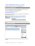
drive.web
smarty
Contents! !
!
!
dw115 - Installation &
Operation Manual
!
!
Page
Warnings, Introduction, Features ! !
!
smarty yf7 Options !!
!
!
!
Winder specials, Physical Installation!
!
Ethernet, savvy Intro & Upgrades ! !
!
smarty yf7 Terminals !
!
!
!
Option 03 - Analog & Logic I/O!
!
!
Options 07, 08 & 11 Encoder Inputs & Control!
Appendices - Function Blocks, Products !
!
1
2
3
3-5
5
5,6
7
8
Warning!
It is essential that you read and understand this entire manual, the entire Yaskawa F7 User Guide and
the entire contents of the savvy software “Help” menu before proceeding with your installation and
product configuration. For more information and to download product manuals and software, go to
www.driveweb.com.
Warning!
Your use of savvy software, drive.web devices and drives may cause motors and machinery to power
up with high voltages or start or operate in an unexpected, dangerous or lethal way. It is essential that
you are completely familiar with savvy and all of the equipment and the system design you are working with before attempting to program or edit a program or connect to any live device.
Warning!
You are entirely responsible for the configuration or use of any drive.web product. By configuring or
using these products you agree to indemnify and hold harmless Bardac Corporation, its’ employees,
directors, officers, distributors and resellers against the consequences of your configuration or use of the
products.
dw115 smarty yf7
Introduction
Take control of your Yaskawa F7, expand your interface and add computation power with this rugged, versatile, and easy to use, process and
drives management system. Create large integrated systems where
processing bandwidths are not affected by system size.
smarty yf7 Features
drive.web Distributed Process Control over Ethernet
Modbus TCP/IP over Ethernet with option 04.
Internet accessible configuration, monitoring & control.
“Drag ‘n drop,” easy connections with graphical documentation.
Automated, on-line upgrades with savvy software.
System libraries Basic, Process Control, Winders, Math & Encoder.
Function Blocks; Extensive drive parameter control and monitoring.
Arithmetic, logic, PID, comparator, filter, latch, timer, counter,
ramps, winder diameter, taper tension, torque compensator, more.
I/O options; Universal In, Analog Out, Digital I/O, Two Encoders, and Ethernet.
dw115 smarty yf7 HG502253 v. 1.0!
www.driveweb.com !
!
!
Page 1/8
smarty yf7 Available Options
smarty yf7 models include drive.web over Ethernet, Distributed Process
Control, comprehensive Yaskawa F7 interface via 19.2 kbps, EIA485 serial connection, Basic Control Function Block Library with arithmetic,
logic, PI, clamps, data switches and more. Please see Appendix A for a
complete listing of function blocks by library and option.
03 I/O Package - UIP’s (7), AOP’s (2), DIO’s(3), 10V Ref. 10mA max.
Seven Universal Inputs multi-range analog, digital, differential
Two Analog Outputs 0 to 10V, 10mA max. 10 bit resolution
Three configurable Digital Inputs or Outputs. 24V, 50mA output.
04 ModbusTCP/IP. Ethernet, 10baseT enabled Modbus slave/server.
05 Process Control. Function Block Library 1 - Math, Logic, PID,
Switches, Comparators, User data log, Profiler, Presets, Latch, Filters,
Counters, Timers and more, see Appendix A.
06 Winder Control Function Block Library 2 - Diameter Calculator,
Taper Tension, Torque Compensator.
07 and 08 Encoder 1 and 2 Inputs. Bi-directional with marker, EIA 422/
485, 24V, 300kHz With encoder logic, position, speed functions.
09 Real time clock-battery backup, calendar, and event time-stamp.
10 Advanced Math Function Block Library 3 - Trig, Polynomials, Log,
Exponent, more, see Appendix A.
11 Encoder Control Function Block Library 4 - Speed Lock, Registration, Position (Requires Option 07 and 08)
smarty yf7 Options Important Notes:
Options 04, 05, 06, 10 and 11 are software options, easily field installed.
Option 08 includes an isolated serial port with green and yellow LEDs that
indicate EIA485 data being received and transmitted.
!
Modbus Option 04 enables communication with a wide range of industrial
devices from drives to operator stations, PLCs and SCADA systems. It is
essential that you read and understand the entire drive.web Modbus
Installation and Operation Manual, HG502421, included with this options before using it.
!
smarty yf7 Winder Specials
Include options 05 and 06, pre-installed generic winder
system configuration and a wiring diagram drawing for
fast commissioning of a wide range of winder applications.
1101 smarty winder 1 Open Loop Constant Tension Center Winder.
1
2
A
SP EED
DEMAND
(0-10 VDC)
-
+
3
4
-
A
24 VDC
SUPP LY
BY OTHER
TORQUE
DEMAND
(0-10 VDC)
+
+
J OG
STRT
TENS
LOAD
-
HLD
B
1102 smarty winder 2 Closed Loop Dancer Control Center Winder.
B
C4
0V
COM
C2
S PEED
DEMAND
C3
TOR QUE
DEMAND
D6
JOG
C5
S TAR T
C6
C7
D7
+24V DC 0VDC
TENS ION LOA D DIAMETE R S UP PL Y S UP PL Y
ENA BLE DIAMETE R HOLD
COM
DEVICE: SM ART Y
SP ECIAL MODI FICATIONS: NONE
MODE L: DW110-1101
OPTIONS: AV AILA BLE -02, -04, -07, -08, -09, -10
0V
COM
D8
WEB
S PEED
D1
R EEL
S PEED
D2
SM 1
TENS ION TA PER EX TER NA L
S ETPOINT S ETPOINT DIAMETE R
D3
D4
D5
+10 VDC
R EF
C1
0V
COM
C8
P3
DIAM ETER
10K,1T
C
C
P2
TAP ER SP
10K,1T
1103 smarty winder 3 Closed Loop Loadcell Control Center Winder.
IS S
A
DATE
12 JAN 0 7
www.driveweb.com !
+
REEL
SP EED
(0-10 VDC)
P1
TENSI ON SP
10K,1T
T. COUR NOW
26 JAN 0 7
T. COUR NOW
07 FEB 07
T. COUR NOW
D
Bardac
40 Lo g Cano e C ircle, Ste ve nsvill e, MD 21 666
ph one (410 ) 6 04-34 00 fax: (4 10) 604 -3500
emai l: i nfo @barda c.com
for m: e ngr/ cad/cad lib /form /asize
dw115 smarty yf7 HG502253 v. 1.0!
+
WEB
SP EED
(0-10 VDC)
APPROVED
B
C
D
!
!
1
SHT. TITLE
DWG. TYPE
JOB TITLE
OPEN LOOP WIN DER
CU ST.
CIRC UIT DIAGRAM
DIST.
SMARTY WIND ER 1: D W1 10-1 101
SAVVY DRIVE.WEB USER
N/A
P.O.
N/A
LOC ATION
DR N.
T. COUR NOW
DESIGN
T. COUR NOW
SCA LE
SIZE
2
3
NONE
SIZE
DWG. NO.
HF50 209 6U0 01
DWG. ISS.
C
JOB NO.
SHT.
4
Page 2/8
N/A
1
OF
1
smarty yf7 Physical Installation
Mount on DIN rail in an electrical enclosure that provides the required environmental protection. You can mount with zero clearance on the side of the drive
but provide at least 5” space if mounting directly above or below the drive.
smarty yf7 Dimensions and Weight: 2.3”w, 4.5”h, 4.7”d (59, 115, 120mm) 1.0 lb (0.45 Kg)
smarty yf7 Power Requirements: Regulated 24VDC ±15%, 50mA plus loads.
smarty is fitted with a 1A auto reset fuse
smarty yf7 Storage and Operation Environment: Temperature range; 0 to 50C.
Humidity less than 95% non-condensing.
smarty yf7 Ethernet Port Standard RJ45 8P8C, 10BaseT, Link and Activity LED’s
Set up Your Yaskawa F7, WARNING!
You must read and understand the entire Yaskawa F7 User Manual before proceeding! Dangerous,
high voltages will exist that may cause injury or death! Only qualified personnel should proceed!
Check parameter U1-14, Flash ID = 3020. This is currently the only supported software.
You will need to connect the terminals, S- and R-, together for EIA485- or A. S+ and R+
connected together make the EIA485+ or B connection. 1G may be connected directly to C.
Set the baud rate at parameter H5-02 to 4 for 19.2 kbps.
Check the Modbus Unit address, Parity and Delay times are at default settings:
H5-01 = 1F = Address, decimal 31
H5-03 = 00 No Parity
H5-06 = 05 Minimum delay, 5ms
Based on your application, set H5-04, Stopping Method and H5-05, Serial Fault Detect.
These parameters determine how the drive will respond to a serial connection loss.
Important Note: You must cycle the YF7 drive’s power, waiting for the screen to blank
before repowering, in order for the changes to take effect.
smarty yf7 Ethernet Networking & Programming
It is important to have a basic understanding of Ethernet TCP/IP networks. smarty yf7 uses
the same IP address format as computers and may disrupt a local network or function improperly
if it is not set up with a unique IP address. smarty yf7s are all shipped with the IP address,
10.189.189.189. Consult your company’s IT department for an appropriate, unique address.
Set up Your Physical Ethernet Network - You Will Need:
A standard Category 5e cable (with 8P8C/RJ-45 connectors on both
ends) for each drive.web device and your computer.
An Ethernet switch with sufficient ports to support all your drive.web
devices and your computer.
Set up Your Computer - Get savvy
The free drive.web savvy software allows you to easily program and monitor your smarty yf7 and create distributed control systems.
You can find useful networking information in the Basic Network Administration Section in the savvy user manual under the, “Help,” menu.
To download the latest version of savvy and to view the savvy user manual, go to www.driveweb.com and click on, “get savvy.”
dw115 smarty yf7 HG502253 v. 1.0!
www.driveweb.com !
!
!
Page 3/8
Windows users will need to have Java Runtime Environment installed to
run savvy. There is a link on this page to download Java for free.
Get started with savvy
Before proceeding with your systems designs it is very important to familiarize yourself with savvy, the configuration software.
!
We strongly recommend that you read the introductory guides, “Getting
Started with savvy,” “Getting Started with savvy-SFD,” and , “savvySFD and the PL series drive.” Find these guides under the Help menu.
!
Use the unique, “ Create Phantom,” feature to practice your design and configuration techniques. Design a system in any Phantom drive.web device
and export it for use in your devices.
We also strongly recommend that you attend one of our regular on-line
training seminars. Contact us at [email protected] or call 410604-3400 to register.
Under the Directory menu, click on, “Discover All Local Devices.” If your
smarty yf7 is powered up and physically connected to the same local network as your computer, an icon should appear on the screen.
If the red padlock icon shown above appears, your computer’s subnet mask is preventing proper communication with the smarty. Under the File menu, click on,
“Administrate - Set IP Addresses for System.” A list will appear with a serial number
that should match the serial number label on the bottom of your smarty.
Enter an IP address within your computer’s subnet mask. A YF7 icon should appear.
The icon with question mark indicates no communication has been made. The clear
icon indicates a good serial connection. The double arrow and yellow triangle instantly warns you if serial communication with the drive is interrupted.
If a red warning triangle is superimposed on the icon, your computer has lost
Ethernet communication with your smarty. Check your Ethernet connections and that your smarty still has 24VDC power.
Right click on the icon and choose, “Change Name,” to name your smarty.
Left click to view the first level, device overview screen. You can access the drive
control and monitoring parameters, the Function Block Engine and if you have
option 04, a Modbus icon. Left click to view the next level.
Left click on function blocks to view and adjust parameters.
Left click on parameters to open the setter box unless they show a crossed-out
pen meaning that they are read-only. You can adjust the parameter value
with mouse or keys.
Right click on parameters to get info, add to a dock, copy, start or end connections, rename, and rescale.
drive.web works with 16 bit words allowing raw decimal integer values 0 to
65535 or ±32767. These raw values are limited and/or scaled depending
on the parameter. This prevents illegal values and presents numbers in the
most useful formats. Right click to adjust scaling to fit your needs. Check
scaling when making connections.
dw115 smarty yf7 HG502253 v. 1.0!
www.driveweb.com !
!
!
Page 4/8
Upgrade savvy with Signal Flow Diagram Option - SFD
With savvy-SFD, implement your systems in a graphical manner and create professional quality engineering drawings that are stored in your smarty.
A
B
C
D
E
User Logger@5067
Linear Ramp@5051
tag
2-In Switch@5047
Watchdog@5071
1
another smarty
data
DIO1 Encoder Select.5109) Output
Set borders, “Drag n’ Drop,” connections, zoom, pan and see your system
clearly. Multi-page drawings with cross-referencing are easy to create.
device log
1
another smarty
Holding Register [email protected]) Last Error
another smarty
another smarty
store
DIO1 Encoder Select.5109) Output
DIO1 Encoder Select.5109) Output
5065) Lay Diameter
0.00 %
Output Scaler
Drum Speed Demand
Output Offset
Comparator@5058
2
2
Integrator@5112
UIP1 Analog Line Speed Input
Drum Speed Demand AOP1
Actual Diameter of Material
Line Speed Input
Material Thickness
100% = 10V
Square Root@5110
C2
D1
dt
Get the savvy-SFD upgrade on-line under the Commerce menu. Select, “Upgrade savvy,” and process a Voucher, coupon or credit card.
x
0% = 0V
SR Latch@5089
Comparator@5100
S
IN / OUT
Q
R
3
3
Drawing Number
Find a guide to this upgrade, “Getting Started with savvy-SFD,” under the help menu.
smarty yf7 Terminals
4
Title
B
C
4
Date
Your smarty
A
Issue
Designed By
Drum Winder App
D
Page
of
1
E
24VDC power supply input
+24V 0V
Serial port with option 08 is isolated.
Includes LEDs, green, data received,
and yellow, data sent.
A B C
Terminal Block A
Encoder 2 Input (Option 08)
10base T Ethernet port, RJ45
with LEDs. Green, link & yellow, activity
for easy programming and networking.
A1 2 3 4 5 6 7 8A
B1 2 3 4 5 6 7 8B
Terminal Block B
Encoder 1 Input (Option 07)
Terminal block C C 1 2 3 4 5 6 7 8 C
10V Ref., Analog Out & Digital Input/Outputs
D1 2 3 4 5 6 7 8D
Terminal Block D
Universal Input/Outputs, 0V Ref.
smarty yf7 Option 03 AOP, DIO & UIP
+24V 0V
Terminal Function
C1 !
+10V Ref.
C2 !
AOUT1
C3 !
AOUT2
C4 !
0V
C5 !
DIO1
C6 !
DIO2
C7 !
DIO3
C8 !
0V
Terminal Function
D1 !
UIP1
D2 !
UIP2
D3 !
UIP3
D4 !
UIP4
D5 !
UIP5
D6 !
UIP6
D7 !
UIP7
D8 !
0V
C1 2 3 4 5 6 7 8C
D1 2 3 4 5 6 7 8D
dw115 smarty yf7 HG502253 v. 1.0!
www.driveweb.com !
!
!
Page 5/8
1
Terminal Block C ~ 10V, Analog Outputs and Digital I/O
smarty + option 03
AOP1@5118
C1, 10V Reference. Supplies 10mA max current.
5119) Monitor
0.00 V
C2, C3, Two Analog Outputs. 0V to 10V, 10mA source,10 bit res.
Input parameter 0% to 100% translates to 0V to 10V output.
100% = 10V
5118) Input
C2
0.00 %
0% = 0V
C5, C6, C7, Three Digital I/O Terminals. Click on the, “Output Enable,” parameter to change from input to output or connect to
dynamically configure. Connect, 0 = Input and 1 = Output.
smarty + option 03
DIO1@5115
5116) Output Enable
Output
Output Configuration; 24V with 50mA max. source current
is output to the terminal when the function block’s input parameter
is set to, “High” or " 1
5115) Input
High
C5
5117) Output
Input Configuration: Input parameter is ignored and output
parameter follows 24V logic at the terminal. High = 1 and Low =
0. Threshold is ~8V with 4V hysteresis. 12V logic may NOT function properly.
High
! 8V
hysteresis ! 4V
smarty + option 03
UIP1 Logic@5107
Terminal Block D ~ Universal Analog/Logic Inputs
5107) Monitor
0.0 V
D1 - D7, Seven UIP’s 100K" input impedance, 12-bit resolution.
D1
5109) Output
Low
You may monitor a terminal as an analog, logic, or differential
input in separate function blocks.
5108) Range
You may dynamically configure logic and analog ranges by connecting to the Range parameter.
24V Logic
UIP Logic Block
Range Parameter!
!
0!
!
!
1!
!
!
2!
!
Set the Differential Block Range to the maximum expected voltage difference between the two input terminals. The output is the
percentage difference between the terminals over this range.
smarty + option 03
smarty + option 03
UIP1 Analog@5110
5110) Monitor
5113) Offset
0.00 V
100.00 %
Logic Range
5V Logic
12V Logic
24V Logic
UIP1&2 Differential@5105
5108) Offset
100.00 %
5105) Monitor
0.00 V
D1
5112) Output
D1
5107) Output
100.0 %
100.0 %
D2
5111) Range
5114) Scaler
±200V
1.000
UIP Analog Block
Range Parameter!
#
0#
#
#
1#
#
#
2#
#
#
3#
#
#
4#
#
Analog Range
± 100 mV
±5V
± 10 V
± 100 V
± 200 V
dw115 smarty yf7 HG502253 v. 1.0!
5106) Range
5109) Scaler
10V
1.000
UIP Differential Block
Range Parameter!
Input Ranges
!
0!
!
100 mV
!
1!
!
5V
!
2!
!
10 V
www.driveweb.com !
!
!
Page 6/8
smarty Option 07 and 08, Encoder Inputs
smarty w/ encoder
ENC1 Speed@5106
5107) Pulses Per Revolution
1024 ppr
B1
Encoder inputs are EIA422/EIA485 receivers, 24V, 300KHz max. freq.
A
5108) Speed
0 RPM
B2
Two function block types provide bidirectional speed and logic information.
5110) Output
0.00 %
B3
Notice that EIA422/485 signals should be complementing differential-type.
The, “+,” line must swing negative with respect to the, “-,” line for proper
operation. A single ended 0 to 24V logic signal may NOT register correctly.
B
5109) Base Speed
B4
1800 RPM
5106) Status
OK
smarty w/ encoder
ENC1 Logic@5111
Option 08 requires option 07.
B1
5111) Output A
High
Speed block includes a status parameter that indicates fault conditions on A
and/or B. Use this parameter to verify your EIA422 signals and connections.
B2
max voltage: ±25V
common-mode:
-10V to +13.2V
B3
5112) Output B
Encoder Terminals:
Enc.1 Opt. 07 !
B1 !
!
B2 !
!
B3!
!
B4 !
!
B5!
!
B6 !
!
B7!
!
B8 !
!
High
B4
Enc.2 Opt. 08
A1!
!
A2!
!
A3!
!
A4!
!
A5!
!
A6!
!
A7!
!
A8!
!
threshold:
0V ± 200mV
Description
Encoder A+
Encoder AEncoder B+
Encoder BEncoder Marker Z+
Encoder Marker Z+24VDC encoder power supply, 200mA max.
0V
hysteresis: ! 45mV
B5
5113) Output Z
High
B6
smarty Option 11 Encoder Control F. B. Library 4
Option 11 requires option 07 and 08 and provides position, speed-lock and registration function blocks.
smarty w/2 encoders+11
ENC1 Position@5115
Encoder Position Function Block
Set up this block for absolute position measurement:
1. Choose mechanical positions for 0 and 100%.
2. Enter number of encoder revolutions required to move from 0 to 100%
3. You may dynamically update your 0% position with a zero-position
signal input connected to the, “Reset,” parameter.
5116) Pulses Per Revolution
5118) Base Revs
60 ppr
10 revs
B1
A
B2
5119) Output
0.04 %
B3
5115) Status
B
OK
B4
5117) Reset
Inactive
Encoder Speed Lock Function Block
smarty w/2 encoders+11
ENC Speed Lock@5109
5111) ENC1 Ratio
Use this block to provide a numerical speed error signal.
Check savvy User Manual, Appendix A for detailed information on the
following system implementations:
1
B1
A
B2
5109) ENC1 Status
OK
B3
B
Create a Master speed follower system:
Condition the error signal through a PID function block and
output a speed reference to a follower drive.
B4
5114) Error
0
A1
A
A2
5110) ENC2 Status
Fault on A and B
A3
B
Create a Phase Lock system:
Condition the error signal through an integrator and PI function
blocks and output to drive.
A4
5112) ENC2 Ratio
5113) Scaler
1
1
smarty w/2 encoders+11
Registration@5102
Encoder Registration Function Block
5103) Master Edge
5105) Measurement
Rising Edge
Time ("s)
C5
DIO1
Use this block to measure time or pulse delay between markers.
! 8V
hysteresis ! 4V
5107) Output
0
C6
Choose whether the registration markers are signals on Digital I/O inputs 1 and 2, Encoder markers Z or combinations of DIO’s and Z’s.
dw115 smarty yf7 HG502253 v. 1.0!
www.driveweb.com !
!
DIO2
! 8V
hysteresis ! 4V
!
5102) Configuration
5104) Slave Edge
5106) Scaler
DIO1 & DIO2
Rising Edge
1
Page 7/8
smarty Appendix A Function Blocks by Library and Option
Bold header indicates function block category. Precursor number is # of parameters inside each block.
Basic smarty
Arithmetic
Control
3 Adder
15 PI
3 Divider
Drive Helper
3 Multiplier
11 Optidrive Helper
3 Subtracter
Logic Gates
Clamps
3 AND
4 Clamp
2 NOT
Process Control Library Option 05
Arithmetic
15 PI
20 PID
3 Differential Splitter
8 Profiler
4 Multiplier-Divider
Counters
3 Sign And Value
3 Sign Changer
17 Up/Down Counter
Clamps
Drive Helper
5 Clamp with Monitor
11 Optidrive Helper
4 Deadband
Filters
4 Skipband
4 Low Pass Filter
Comparators
5 Moving Average Filter
4 Comparator
Latches
5 Equality Comparator
4 D Latch
3 Maximum
5 D Latch with Reset
3 Minimum
5 D Latch with Set
6 Window Comparator
6 D Latch w/Set, Reset
Control
3 SR Latch
6 Differentiator
4 T Latch
8 Integrator
Option 02, 04
Option 06
Utility
Winder
4 Modbus Indirect
18 Diameter Calculator
7 Taper Tension
30 Torque Compensator
Option 03
I/O
2 AOP’s
Options 07,08
3 DIO’s
I/O
5 UIP Differential
3 ENC Logic
5 UIP Analog
5 ENC Speed
3 UIP Logic
3 OR
Switches
4 2-In Switch
4 2-Out Switch
Utility
1 Dev. Comms Monitor
1 Indicator
4 Parameter Block
6 Watchdog
1 Watchdog Driver
Logic
17 16-Bit Binary Encod.
17 16-Bit Binarty Decod.
5 4-Bit Binary Encoder
16 4-Bit Priority Encod.
3 Bitwise AND
2 Bitwise NOT
3 Bitwise OR
3 Bitwise Shift
3 Bitwise XOR
Logic Gates
3 NAND
3 NOR
3 XNOR
3 XOR
Ramps
7 Linear Ramp
11 MOP
17 S Ramp
Switches
18 16-In Switch
18 16-Out Switch
6 4-In Switch
6 4-Out Switch
10 8-In Switch
10 8-Out Switch
3 Track and Hold
Timers
5 Delay-Off Timer
5 Delay-On Timer
3 One Shot
5 Oscillator
8 Underlap
Utility
4 User Logger
Option 10
Math
2 ArcCosine
2 ArcSine
2 ArcTangent
2 Cosine
2 Cube
2 Cube Root
2 Exponential
2 Logarithm
2 Reciprocal
2 Sine
2 Square
2 Square Root
2 Tangent
Option 11
I/O
5 ENC Position
6 ENC Speed Lock
7 Registration
Option 12
ModbusRTU Master
7 Comms Port
48EurothermERCFW09
6 Holding Reg. INT16
6 Holding Reg. UINT16
54 Optidrive Plus
54 Optidrive VTC
48 WEG CFW09
Appendix B drive.web Product Line Overview
smarty Full featured DPC that simultaneously manages many varied process components and drives.
speedy sp and speedy485 Processing power, tailored for your drive or generic, Ethernet, EIA485
savvy Signal Flow Diagram Option Easily implement your systems designs. “Drag n’ Drop,”
connections with complete, graphical documentation created in one step and stored in your device.
drive.web Training Courses-an essential component in your drive.web system. On-line and factory
courses are available at all technical levels. Sign up to get the most out of your drive.web technologies.
drive.web 40 Log Canoe Circle, Stevensville, MD 21666 USA.
Ph. 410-604-3400, Fax 410-604-3500, www.driveweb.com
dw115 smarty yf7 HG502253 v. 1.0!
www.driveweb.com !
!
!
Page 8/8