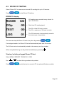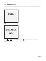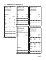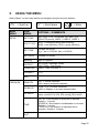
1
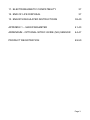
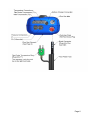
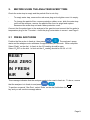
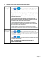
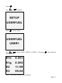
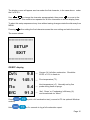
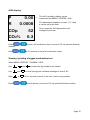
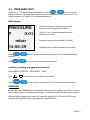
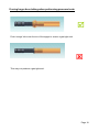
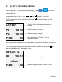
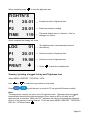
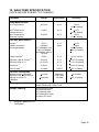
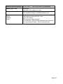
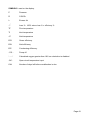
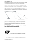
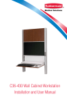
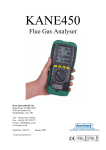
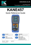
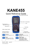
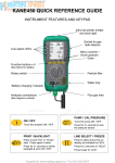
KANE451plus Flue Gas Analyser with direct CO2 measurement Stock No: 19500-2 © Kane International Ltd August 2014 CONTENTS Page No: KANE451plus Overview ANALYSER LAYOUT & FEATURES 1. BATTERIES 2. BEFORE USING THE ANALYSER EVERY TIME 2.1 2.2 FRESH AIR PURGE STATUS DISPLAY 4 5-6 7 8-9 8 9 3. USING THE FOUR FUNCTION BUTTONS 10-12 4. USING THE ANALYSER 13-24 4.1 4.2 4.3 4.4 4.5 4.6 4.7 COMBUSTION TESTS PRESSURE TEST LET-BY & TIGHTNESS TESTING DIFFERENTIAL TEMPERATURE ROOM CO TESTING MEMORY FULL KANE451plus PRINTOUTS 13-16 17-18 19-20 21 22 23 24 5. USING THE MENU 25-26 6. USING THE KANE451plus AS A THERMOMETER OR PRESSURE METER 27-28 7. MEASURING FLUE GASES 29 8. ANALYSER PROBLEM SOLVING 30 9. ANALYSER ANNUAL SERVICE & RE-CERTIFY 9.1 RETURNING YOUR ANALYSER TO KANE 9.2 SERVICE RETURNS 31-33 32 33 10. ANALYSER SPECIFICATION 35-36 Page 2 11. ELECTROMAGNETIC COMPATIBILITY 37 12. END OF LIFE DISPOSAL 37 13. EN50379 REGULATED INSTRUCTIONS 38-40 APPENDIX 1 – MAIN PARAMETER 41-43 ADDENDUM - OPTIONAL NITRIC OXIDE (NO) SENSOR 44-47 PRODUCT REGISTRATION 49-50 Page 3 KANE451plus Overview The KANE451plus Combustion Analyser measures carbon dioxide (CO2), carbon monoxide (CO), differential temperature and differential pressure. The direct measurement of CO2 is achieved using a Kane designed infra-red sensing system. CO2 is set to zero in fresh air automatically after the initial countdown. If “RESET GAS ZERO” is indicated ensure that the unit is in fresh air before pressing the button with an “Enter” symbol. It calculates oxygen (O2), CO/CO2 ratio, losses, combustion efficiency (Nett, Gross or Condensing) & excess air. The KANE451plus Combustion Analyser can also measure CO levels in ambient air useful when a CO Alarm is triggered. It can also perform a Room CO Test for up to 30 minutes duration. The analyser has a protective rubber cover with a magnet for “hands–free” operation and is supplied with a flue probe with integral temperature sensor. The large display shows 4 readings at a time and all data can be printed via an optional infrared printer. The printed data can be 'live' data or ‘stored’ data. The memory can store up to: 99 combustion tests 20 pressure tests 20 let-by/tightness tests 20 temperature tests 20 room CO tests Two lines of 20 characters can be added to the header of printouts. The analyser is controlled using 4 function buttons and a rotary dial. The four buttons (from left to right) switch on and off the analyser, switch on and off the backlight and task light, switch on and off the pump and send data to a printer or to the memory. The buttons with UP, DOWN and ENTER arrows also change settings such as date, time, fuel, etc. when in MENU mode. Page 4 ANALYSER LAYOUT & FEATURES Tasklight and infra-red emitter Menu controls Scroll up/down Function buttons x 4 Enter Particle Filter Rotary Switch Battery Compartment (behind rubber sleeve) Water Trap “Battery Charging” indicator Temp and pressure connections Flue Gas Inlet Page 5 Page 6 1. BATTERIES Battery Type This analyser has been designed for use with disposable alkaline batteries or rechargeable Nickel Metal Hydride (NiMH) batteries. No other battery types are recommended. WARNING The battery charger unit must only be used when NiMH batteries are fitted. Do not mix NiMh cells of different capacities or from different manufacturers. All four cells must be identical. Replacing Batteries Turn over the analyser, remove its protective rubber cover and fit 4 “AA” batteries in the battery compartment. Take great care to ensure they are fitted with the correct battery polarity. Replace the battery cover and protective rubber cover. Switch the analyser on and check that the analyser’s time and date are correct. To reset see USING THE MENU, Section 5. Charging NiMH Batteries Ensure that you use the correct charger. The part number is 19278. To fully charge NiMH batteries: Switch the KANE451plus on. The charger must then be connected and switched on. When charging, the red Battery Charging Indicator will illuminate. Now switch the KANE451plus off. The display will show “BATTERY CHARGING” The first charge should be for 12 hours continuously. NiMH batteries are suitable for top up charging at any time, even for short periods. An in-vehicle charger can be used to top up the analyser's batteries from a 12 volt vehicle battery. The part number is KMCU450/12. Battery Disposal Always dispose of depleted batteries using approved disposal methods that protect the environment Page 7 2. BEFORE USING THE ANALYSER EVERY TIME: Check the water trap is empty and the particle filter is not dirty: - To empty water trap, unscrew the red screw plug and re-tighten once it is empty. - To change the particle filter, remove protective rubber cover, slide the water trap unit from the analyser, remove the particle filter from its spigot and replace. Reconnect the water trap unit and rubber protective cover. Connect the flue probe hose to the analyser’s flue gas inlet and connect the flue probe’s temperature plug to the T1 socket – check the plug’s orientation is correct - see Page 6. 2.1 FRESH AIR PURGE Position the flue probe in fresh air, then press / . The analyser’s pump starts and the analyser auto-calibrates for approximately 90 seconds. When complete: Select “Ratio” on the dial. In fresh air the CO reading should be zero. Select “O2/Eff” on the dial. In fresh air the O2 reading should be 20.9% ± 0.1%. RESET GAS ZERO IN FRESH AIR This message indicates that the analyser needs to be reset in fresh air. To do so, ensure that the analyser is in fresh air and press / . To perform a manual ‘Gas Zero’, select ‘Ratio’ on the dial, hold down the key and you will see the message above. Page 8 2.2 STATUS DISPLAY Select “Status” on the dial to view the following: Replace alkaline batteries if less than 1 bar BAT → Recharge NiMH batteries if less than 2 bars 14:56:29 → Current time. Can be re-set via the “Menu”. 11/03/06 → Current date. Can be re-set via the “Menu”. CAL → re-certification is due. 283 Shows number of days until next SAFETY WARNING This analyser extracts combustion gases that may be toxic in relatively low concentrations. These gases are exhausted from the back of the instrument. This analyser must only be used in well-ventilated locations by trained and competent persons after due consideration of all the potential hazards. Users of portable gas detectors are recommended to conduct a “bump” check before relying on the unit to verify an atmosphere is free from hazard. A “bump” test is a means of verifying that an instrument is working within acceptable limits by briefly exposing to a known gas mixture formulated to change the output of all the sensors present. (This is different from a calibration where the instrument is also exposed to a known gas mixture but is allowed to settle to a steady figure and the reading adjusted to the stated gas concentration of the test gas). Page 9 3. USING THE FOUR FUNCTION BUTTONS: Switching ON the Analyser Press / button to switch the unit ON. This must be done in fresh air to ensure that the analyser auto calibrates its sensors properly. When switched on, the analyser beeps and briefly displays battery %, fuel and pressure units. Its bottom line counts down from 90 until the sensors are ready to use. If the analyser will not auto calibrate, its sensors need to be replaced or recalibrated by an authorised repair centre. If an inlet temperature probe (optional) is connected into the T2 socket during its countdown, the measured temperature from the inlet probe will be used as the inlet temperature. If an inlet temperature probe is not connected to the analyser during countdown the measured temperature from the flue probe will be used as the inlet temperature. If neither probe is connected during countdown the analyser’s internal ambient temperature will be used as the inlet temperature. Switching OFF Press / button to switch the analyser OFF. The the Analyser display counts down from 30 with the pump on to clear the sensors with fresh air – If the probe is still connected, make sure analyser and probe are in fresh air. Press / if you want to stop the countdown and return to making measurements. Note: The analyser will not switch off unless the CO reading is below 20ppm. Page 10 Backlight & Tasklight Press / tasklight on and off. to switch the display's backlight and NOTE: Use of the backlight/tasklight significantly increases the current drain on the batteries. Switching PUMP on / off The analyser normally operates with the pump on. Press / to switch the pump off and on. When the pump is switched off “-PO-" is displayed instead of the O2, CO & CO2 readings. The analyser also displays "PUMP OFF" on the top line approx every 40 seconds. NOTES: 1) The pump will not switch off if the CO reading is above 20ppm . This helps to protect the CO sensor from damage. 2) The pump will automatically switch itself off when the rotary switch is set to Menu, Status, Pressure, Tightness or Differential Temperature. Zeroing the pressure sensor Printing Data To re-zero the pressure sensor when “Prs” is selected on the dial, press and hold CAL ZERO. / until the top line display shows Press and quickly release / to start the analyser printing. The analyser displays a series of bars until this is completed. Press and release the key again to abort printing. Make sure the printer is switched on, ready to accept data and its infrared receiver is in line with the analyser’s emitter (on top of the analyser). Page 11 Storing a set of readings Press and hold / for approx. 2 seconds. The top line briefly displays the log number. Note: This STORE function is inhibited in normal operation if the pump is switched off. Using / Buttons / / / are used The function buttons below the symbols to navigate through the menu when the rotary switch is set to MENU – See USING THE MENU, Section 5. Page 12 4. USING THE ANALYSER: 4.1 COMBUSTION TESTS: Insert the tip of the flue probe into the centre of the flue. The readings will stabilise within 60 seconds assuming the boiler conditions are stable. The rotary switch can be used to display the following information: RATIO Display NAT GAS → Fuel type can be changed via “Menu”. R → CO/CO2 ratio. 0.0008 COp 52 → Carbon monoxide (ppm). CO2% 6.3 Press module). to print a full combustion test, (or send to PC via optional Wireless Hold / / → Carbon dioxide (%). for 2+ seconds to log a full combustion report. SETTING USERFUEL Rotate dial to MENU, screen shows MENU SETUP Page 13 Press Use or to display: SETUP USERFUEL Press , screen shows: USERFUEL USER1 Use or typically show: to select USER 1, USER 2 or USER 3. Then press K1n 0.351 K1g 0.393 K2 11.89 K3 09.83 , the screen will NOTE: The actual numbers may be different. Page 14 The display cursor will appear as a bar under the first character, in the case above: under the 0 of 0.351. Use / to change the character as appropriate, then press to move to the next character. This needs to be repeated for all four characters on all four display lines. To abort this setup sequence at any time without saving changes rotate the dial away from MENU. Pressing after setting the final character saves the user setting and exits the routine. The screen shows: ----------------SETUP EXIT ----------------O2/EFF display O2% 9.8 TFc 145.1 TIc 5.4 EfC 91.3 Press module). Hold / / Oxygen (%) left after combustion. Should be → 20.9% ± 0.1% in fresh air. o → Flue temperature ( C). → Inlet temperature (oC). Normally set by flue probe during fresh air purge. ‘Net’, ‘Gross’ or ‘Condensing’ efficiency (%) → can be selected via “Menu”. to print a full combustion test, (or send to PC via optional Wireless for 2+ seconds to log a full combustion report. Page 15 AUX display P 0.00 R 0.0008 COp 52 → The AUX (auxillary) display can be customised via MENU / SCREEN / AUX. The parameters displayed on lines 1, 2, 3 and 4 can be set by the user. They remain the AUX parameters until changed by the user. CO2% 6.3 Press module). to print a full combustion test, (or send to PC via optional Wireless / Hold / for 2+ seconds to log a full combustion report. Viewing / printing a logged combustion test Select MENU / REPORT / COMB’N / VIEW Use , and to select the log number to be viewed. Use and to scroll through the individual readings on lines 2 & 3. Hold or for 2+ seconds to scroll to the next / previous log number. Press / to print the test, (or send to PC via optional Wireless module). Page 16 4.2 PRESSURE TEST Select “Prs”. The pump stops automatically. Press / to auto-zero the pressure sensor. Using the black connectors and manometer hose, connect to P1 for single pressure or P1 and P2 for differential pressure. PRS display Normal response or smoothed (damped) PRESSURE → response can be selected via “Menu”. P → selected via “Menu”. 0.01 mbar 14:56:29 Press module). / / Hold ‘High’ or ‘Low’ resolution readings can be → Pressure units can be selected via “Menu”. → Displays time to enable manually timed tests. to print a full pressure test, (or send to PC via optional Wireless for 2+ seconds to log a pressure report. Viewing / printing a logged pressure test Select MENU / REPORT / PRESSURE / VIEW Use or Press to select the log number to be printed. / to print the test, (or send to PC via optional Wireless module). WARNING Before using the KANE451plus to measure the pressure of a gas/air ratio valve, read the boiler manufacturer’s instructions thoroughly. If in doubt contact the boiler manufacturer. After adjusting a gas/air ratio valve it is essential that the CO, CO2 and CO/CO2 ratio readings are within the boiler manufacturer’s specified limits. Page 17 If using larger bore tubing when performing pressure tests: Push ‘orange’ tube over the rim of the spigot to ensure a gas tight seal. This may not produce a gas tight seal. Page 18 4.3 LET-BY & TIGHTNESS TESTING Select “Tightness”. The pump stops automatically. Press / to auto-zero the pressure sensor. Connect from the test point to P1 using a black connector and manometer hose. The display shows “LET BY?”. Use , and If YES is selected set the let-by pressure then press display shows: to select YES or NO. to start the let-by test. The The let-by test is automatically stored in the LET BY → memory. P1 10.15 → Pressure at start of let-by test. P2 10.15 → Real time pressure reading. TIME 59 Let-by default time is 1 minute. Can be → changed via “Menu”. If the let-by test fails simply move the rotary switch to any position other than “tightness” to abort the test. If the let-by test passes adjust the gas pressure for the tightness test and press start the stabilisation test. The display shows: to STABIL’N P1 20.01 mbar TIME → Real time pressure reading. → Pressure units. 59 Stabilisation default time is 1 minute. Can be → changed via “Menu”. Page 19 When complete press to start the tightness test: TIGHTN’S P1 20.01 → Pressure at start of tightness test. P2 20.01 → Real time pressure reading. TIME 119 Tightness default time is 2 minutes. Can be → changed via “Menu”. When complete the display will show: LOG 01 The tightness test is automatically stored in → the memory. P1 20.01 → Pressure at start of tightness test. P2 19.98 → Pressure at end of tightness test. PRINT → Press to print the complete test. Viewing / printing a logged Let-by and Tightness test Select MENU / REPORT / TIGHTN’S / VIEW Use Press or to select the log number to be printed. / to print the test, (or send to PC via optional Wireless module). Note: The analysers’s memory can store up to 20 tightness tests. Tightness tests are logged automatically therefore the tightness section of the memory will be full after the 20th tightness test is complete. Before the 21st tightness test can be performed the tightness section of the memory must be cleared. To do this select MENU / REPORT / TIGHTN’S / DEL ALL / YES then press . Page 20 4.4 DIFFERENTIAL TEMPERATURE Select “Diff Temp” to measure flow, return and differential temperatures DIFF TEMP display Pump stops automatically when dial is moved TEMP → to Diff Temp. Use the T1 connection for the flow T1c 60.4 → temperature sensor. T2c 55.2 → temperature sensor. ∆Tc 5.2 Press / Wireless module). to print a differential temperature test, (or send to PC via optional Hold / Use the T2 connection for the return → Real time temperature difference. for 2+ seconds to log a differential temperature report. Viewing / printing a differential temperature test Select MENU / REPORT / TEMP / VIEW Use Press or to select the log number to be printed. / to print the test, (or send to PC via optional Wireless module). Page 21 4.5 ROOM CO TESTING Select “Room CO” to measure and record CO readings for up to 30 minutes. Press / to start Room CO testing. ROOM CO display ROOM CO CO readings are recorded every minute for up to 30 minutes. COp 00 → Real time CO reading (ppm). TEST 00 → Test 30 = maximum of 30 tests in series. LOG 01 → The CO test series is automatically stored in Test 00 = initial CO test in series. the memory as a log number. The user can stop the Room CO test at any time by pressing / . If not stopped earlier, the Room CO test will automatically end after 30 minutes. The CO test series is automatically stored in the memory as a log number. When completed the log can be printed immediately by pressing . Viewing / printing a logged Room CO test Select MENU / REPORT / ROOM CO / VIEW Use Press or to select the log number to be printed. / to print the test, (or send to PC via optional Wireless module). Page 22 4.6 MEMORY FULL When test sequences are stored, if the memory capacity is exceeded, the display shows: FULL then DEL ALL? NO Use or to select YES, then press to delete that memory section. NOTE: Be sure to print any data that you need first. Page 23 4.7 KANE451plus PRINTOUTS KANE451plus V 1.00B KANE451plus V 1.00B KANE451plus V 1.00B YOUR COMPANY NAME & PHONE NUMBER HERE YOUR COMPANY NAME & PHONE NUMBER HERE YOUR COMPANY NAME & PHONE NUMBER HERE SERIAL NO. 000000000 SERIAL NO. 000000000 SERIAL NO. 000000000 PRESSURE DIFF TEMP DATE TIME 01/07/14 12:00:08 DATE TIME COMBUSTION FUEL O2 CO2 CO FLUE INLT NETT % % ppm o C o C o C NAT GAS 5.4 8.8 12 55.1 17.2 37.9 EFF (C) 98.3 LOSSES 1.7 XAIR % 34.8 ----------------------------------------------------Cal. due on 01/07/15 ----------------------------------------------------CO/CO2 0.0001 PRS 01/07/14 12:00:08 mbar -0.037 DATE TIME T1 T2 ∆T 01.07/14 12:00:08 o C C o C o Customer Appliance Customer Ref. Appliance Ref. KANE451plus V 1.00B YOUR COMPANY NAME & PHONE NUMBER HERE KANE451plus SERIAL NO. 000000000 YOUR COMPANY NAME & PHONE NUMBER HERE Customer ROOM CO TEST SERIAL NO. 000000000 Appliance LOG DATE TIME PRS Ref. mbar 0.00 60.1 47.0 13.1 TEST 0 1 2 3 4 5 6 7 8 9 01 01/07/14 12:00:08 CO ppm LOG DATE TIME 04 01/07/14 12:00:08 LET BY TEST PRS-1 PRS-2 LET-BY mbar mbar MINS 10.12 10.11 1:00 TIGHTNESS TEST 30 MAXIMUM CO V 1.00B PRS-1 PRS-2 ∆PRS mbar mbar mbar 20.12 20.10 -0.02 STABIL’N TIGHTN’S MINS MINS 1:00 2:00 11 Customer Customer Appliance Appliance Ref. Ref. Page 24 5. USING THE MENU Select “Menu” on the rotary switch and navigate using the function buttons: = Scroll up = Scroll down = Enter MAIN MENU SUB MENU OPTIONS / COMMENTS SETUP SET FUEL NAT GAS, L OIL, PROPANE, BUTANE, LPG, PELLETS (wood), USER 1, USER 2, USER 3 NCG Ef(C) = condensing boiler nett efficiency Ef(N) = nett efficiency, Ef(G) = gross efficiency SET TIME HH:MM:SS format e.g. 7 am = 07:00:00, 7pm = 19:00:00 SET DATE DD/MM/YY format ppm/mg ppm or mg/kWh OUTPUT STD PRN = Standard Printer FAST PRN = Fast Printer USERFUEL User 1, User 2 or User 3 PASSKEY 1111 EXIT PRESSURE SMOOTH OFF = normal response. ON = slower (damped) response RESOLVE LOW = e.g. 0.01mbar resolution. HIGH = displays to an extra decimal place PS UNITS mbar, mmH2O, Pa, kPa, PSI, mmHg, hPa, InH2O TIME LET BY = Set duration of let-by test in minutes. Default = 1 minute STABIL’N = Set duration of stabilisation in minutes. Default = 1 minute TIGHTN’S = Set duration of tightness test in minutes. Default = 2 minute EXIT Page 25 MAIN MENU SUB MENU OPTIONS / COMMENTS REPORT COMB’N Stored combustion tests: VIEW, DEL ALL, EXIT PRESSURE Stored pressure tests: VIEW, DEL ALL, EXIT TIGHTN’S Stored tightness tests: VIEW, DEL ALL, EXIT TEMP Stored differential temperature tests: VIEW, DEL ALL, EXIT ROOM CO Stored room CO tests: VIEW, DEL ALL, EXIT EXIT SCREEN CONTRAST Factory setting is 04 AUX Enables users to customise the parameters on the AUX display: LINE 1, LINE 2, LINE 3, LINE 4, EXIT HEADER Printout header, 2 lines, 20 characters per line: HEADER 1, HEADER 2, EXIT EXIT SERVICE NOTE: CODE Password protected for authorised service agents only. Leave set to 0000. To EXIT the MENU at any time simply move the rotary switch to any position other than “Menu”. Any changes that have not been “entered” will be ignored. Page 26 6. USING THE KANE451plus AS A THERMOMETER OR PRESSURE METER With the KANE451plus switched off, press and hold down the / then press and release displayed on top line. . Release / / button and after MANO_MOD is The KANE451plus will now operate as a fixed display thermometer/pressure meter with the pump off and inhibited. The readings can be printed but not stored. The display will show: P 0.00 → Real time pressure reading. T1 21.3 → temperature sensor. T2 21.3 → temperature sensor. ∆T 0.0 Use the T1 connection for the flow Use the T2 connection for the return → Real time temperature difference. The standard printout for this mode is as follows: K451plus V1.00B YOUR COMPANY NAME & PHONE NUMBER HERE SERIAL NO. 000000000 DATE TIME 15/05/07 13:00:47 …………….………………………… T1 T2 ∆T o C C o C o 21.3 21.3 0.0 PRS mbar 0.00 ……………………………………… ……. Ref. ……………………………………… ……. Exit ‘Mano-Mod’ by switching the KANE451plus off. The ‘Menu’ and ‘Tighness’ positions still operate normally in ‘Mano-Mod’ Page 27 If using larger bore tubing when performing pressure tests: Push ‘orange’ tube over the rim of the spigot to ensure a gas tight seal. This may not produce a gas tight seal. Page 28 7. MEASURING FLUE GASES After the countdown is finished and the analyser is correctly set up, put its flue probe into the appliance’s sampling point. The tip of the probe should be at the centre of the flue. Use the flue probe’s depth stop cone to set the position. With balanced flues, make sure the probe is positioned far enough into the flue so no air can ‘back flush’ into the probe. NOTE: Ensure that the flue probe handle does not get hot! Make sure you do not exceed the analyser’s operating specifications. In particular: Do not exceed the flue probe’s maximum temperature (600oC) Do not exceed the analyser’s internal temperature operating range Do not put the analyser on a hot surface Do not exceed the water trap’s levels Do not let the analyser’s particle filter become dirty and blocked View the displayed data to ensure that stable operating conditions have been achieved and the readings are within the expected range. / to start the analyser printing. The analyser Press and quickly release displays a series of bars until this is completed. Press and release the key again to abort printing. Make sure the printer is switched on, ready to accept data and its infrared receiver is in line with the analyser’s emitter (on top of the analyser). Page 29 8. ANALYSER PROBLEM SOLVING If any problems are not solved with these solutions, contact us or an authorized repair center. Fault symptom Causes / Solutions Oxygen too high Air leaking into probe, tubing, water trap, connectors or internal to analyser. CO2 too low CO reading (- - - -) Analyser was stored in a cold environment and is not at normal working temperature. CO sensor needs replacing. Batteries not holding charge Batteries exhausted. Analyser not running on mains adapter. AC charger not giving correct output. Analyser does not respond to flue gas Particle filter blocked. Fuse blown in charger plug. Probe or tubing blocked. Pump not working or damaged with contaminants. Net temperature or Efficiency calculation incorrect. Ambient temperature set wrong during Automatic Calibration. Flue temperature readings erratic Temperature plug reversed in socket. Faulty connection or break in cable or plug. T flue or T nett displays (-OC-) Probe not connected. Faulty connection or break in cable or plug. Ratio, EFF, X-Air all display (- - - -) CO2 reading is below 2%. Analyser just continually beeps Turn dial back to MENU and press ENTER Turn dial back to Tightness and press ENTER Page 30 9. ANALYSER ANNUAL SERVICE & RE-CERTIFY Although sensor life is typically more than five years, the analyser should be serviced and re-certified annually to counter any long-term sensor or electronics drift or accidental damage. Local regulations may require more frequent re-certification. Kane International has service facilities at Atherton near Manchester Tel: 01942-873434 (the primary service centre for UK customers) and at Welwyn Garden City in Hertfordshire Tel: 01707-375550 (the primary service centre for non-UK customers). By sending your analyser back to Kane for an annual fixed price service (check www.kane.co.uk for details) you have the opportunity to extend the warranty on your analyser to 5 years. Page 31 9.1 RETURNING YOUR ANALYSER TO KANE When returning your KANE451plus, please always ensure that you enclose: Your full contact details A daytime telephone number Details of faults you might have experienced Packing your analyser When returning your analyser, please pack it appropriately to prevent any damage during transit. Before sealing your package, please ensure that you have enclosed the items listed above and that it is clearly marked for the attention of: Northern Service Centre Kane International Ltd Gibfield Park Avenue Atherton Manchester M46 0SY Southern Service Centre Kane International Ltd Kane House, Swallowfield Welwyn Garden City Hertfordshire AL7 1JG Sending your analyser Once the analyser has been securely packed then your package is ready for shipment back to Kane. If you do not have an account with a courier company you can take your package to your local Post Office. It is advisable to send the package by Special Delivery so that it is insured and traceable while in transit. When we receive your analyser On receipt of your package, our Service Engineers will inspect the analyser and any accessories and confirm to you the total service cost. Once you have accepted this the work will be carried out, and upon completion the analyser returned to you. If you have any questions that we haven’t answered, please feel free to contact our Northern Service Centre: Tel: 01942 873434 Fax: 01942 873558 Email: [email protected] Tel: 01707 384834 Fax: 01707 384833 Email: [email protected] Page 32 9.2 Service Returns (Simply cut out and attach to your package) Northern Service Department Kane International Ltd Gibfield Park Avenue Atherton Manchester M46 0SY Southern Service Department Kane International Ltd Kane House, Swallowfield Welwyn Garden City Hertfordshire AL7 1JG Northern Service Department Kane International Ltd Gibfield Park Avenue Atherton Manchester M46 0SY Page 33 Page 34 10. ANALYSER SPECIFICATION (NOTE: MAY BE SUBJECT TO CHANGE) Parameter Range Resolution Accuracy Flue Temperature 0-600oC 0.1oC +2.0oC +0.3% reading Inlet Temperature (Internal sensor) 0-50oC 0.1oC +1.0oC +0.3% reading Inlet Temperature (External sensor) 0-600oC 0.1oC +2.0oC +0.3% reading 0-21% 0.1% +0.3% 0-20ppm 21-4,000ppm nom 4,001-10,000ppm 20,000ppm max for 15 mins 1ppm +3ppm +5% of reading +10% of reading 0-20% 0.1% +0.3% volume 0-99.9% 0.1% +1.0% of reading 0-119.9% 0.1% +1.0% of reading 0-250% 0.1% +0.2% of reading 0-0.999 0.0001 +5% of reading +1 mbar Maximum 0.001 mbar <25mbar +0.05 mbar Temp Measurement Flue Gas Measurement Oxygen *2 Carbon monoxide (H2 compensated) *1 Carbon dioxide *1 Efficiency (Net or Gross) Efficiency High (C) *2 *2 Excess Air *2 CO/CO2 ratio *2 Pressure (differential) Nominal range +1600mbar Maximum over range without damage to sensor is +800mbar +160 mbar +3% of reading Pre-programmed Fuels Natural gas, Propane, Butane, LPG, Light Oils (28/35 sec), Wood Pellets plus 3 User Fuels Storage Capacity 99 Combustion tests 20 Pressure tests 20 Tightness tests 20 Temperature tests 20 Room CO tests *1 *2 Using dry gases at STP Calculated Page 35 Ambient Operating Range 0oC to +45oC Battery Type / Life 4 AA cells >8 hours using Alkaline AA cells Chargers (optional) 220v charger, for NiMH batteries only 12v in vehicle charger, for NiMH batteries only Dimensions Weight: Handset: Probe: 10% to 90% RH non-condensing 0.8kg handset with protective cover 200 x 45 x 90mm 300mm long including handle. 6mm diameter x 240mm long stainless steel shaft with 3m long neoprene hose. Type K thermocouple Page 36 11. ELECTROMAGNETIC COMPATIBILITY European Council Directive 89/336/EEC requires electronic equipment not to generate electromagnetic disturbances exceeding defined levels and have adequate immunity levels for normal operation. Specific standards applicable to this analyser are stated below. As there are electrical products in use pre-dating this Directive, they may emit excess electromagnetic radiation levels and, occasionally, it may be appropriate to check the analyser before use by: Use the normal start up sequence in the location where the analyser will be used. Switch on all localized electrical equipment capable of causing interference. Check all readings are as expected. A level of disturbance is acceptable. If not acceptable, adjust the analyser’s position to minimize interference or switch off, if possible, the offending equipment during your test. At the time of writing this manual (June 2014) Kane International Ltd are not aware of any field based situation where such interference has occurred and this advice is only given to satisfy the requirements of the Directive. This product has been tested for compliance with the following generic standards: EN 61000-6-3 : 2011 EN 61000-6-1 : 2007 and is certified to be compliant Specification EC/EMC/KI/KANE451plus details the specific test configuration, performance and conditions of use. 12. END OF LIFE DISPOSAL The Waste Electrical or Electronic Equipment (WEEE) Directive requires countries in the EU to maximise collection and environmentally responsible processing of these items. Products are now labelled with a crossed out wheeled bin symbol to remind you that they can be recycled. Please Note: Batteries used in this instrument should be disposed of in accordance with current legislation and local guidelines. Page 37 13. EN 50379 REGULATED INSTRUCTIONS EN 50379 Section 4.3.2 “Instructions” defines a number of specific points that must be included in the relevant instruction manuals. The paragraph numbering below relates to that section of EN 50379. a) The KANE451plus is compliant the EN 50379 Part 2 and Part 3 as detailed in the third party approvals issued by TUV. b) The KANE451plus is intended to be used with the following fuels: Natural gas Light oil (28/35 sec) Propane LPG Wood pellets Butane c) The KANE451plus is designed for use with either non-rechargeable alkaline AA cells or rechargeable NiMh AA cells. Four cells are needed. Types cannot be mixed. Under no circumstances should any attempt be made to recharge alkaline cells. The battery charger supplied with the KANE451plus is rated for indoor use only. Its voltage input must be in the range 100 – 240 V ac at 50 – 60 Hz with a current capability of 0.3 A. The chargers output voltage is 9 V dc at a maximum of 0.66A. The charger has no user serviceable components. Only a correctly specified and rated charger must be used with the KANE451plus. d) The KANE451plus is not designed for continuous use and is not suitable for use as a fixed safety alarm. e) An explanation of all the symbols used on the analyser’s display is given in Appendix 1 of this manual. f) The recommended minimum time required to perform one complete measurement cycle and achieve correct indication of the measured values in EN 50379 Part 2 is 110 seconds. This is based on the T90 times defined in the standard, always assuming that parameters being measured have reached stability. This time is the summation of the times for a draught test (10 secs) and a combustion test (90 secs) plus the time to move the hose connection from the pressure input to the water trap (10 secs) g) The recommended minimum time required to perform one checking procedure in EN 50379 Part 3 is 110 seconds as described in section f) above. Page 38 h) Some commonly occurring materials, vapour or gases may affect the operation of the KANE451plus in the long or the short term though in normal use Kane International Ltd is not aware of any specific issues that have affected the product. The following list is included to satisfy the stated requirements of EN 50379: Solvents Cleaning fluids Polishes Paints Petrochemicals Corrosive gases i) The KANE451plus is fitted with an electrochemical CO sensor and an infra-red CO2 sensor which have an expected life of more than 5 years. The calibration of these sensors must be confirmed on an annual basis. The batteries have an expected operational life of more than 500 re-charge cycles. j) The KANE451plus is designed to operate at ambient temperatures in the range 0oC to +45oC with relative humidity of 10% to 90% non-condensing. Whilst it is recommended that the analyser is given the protection of a carry case during transportation it is not required for normal operation. k) The KANE451plus has an initial start up delay following switch on of approx. 90 seconds. There is no additional delay after battery replacement. l) Most sensors used in combustion analysers give a zero output when they fail and it is widely recommended that analysers are regularly checked (also known as a bump test) using either a can of test gas or a known source of combustion products. The KANE451plus must have its calibration checked on an annual basis and be issued with a traceable Certificate of Calibration. The sensor within the KANE451plus can only be replaced by Kane International Ltd or one of its trained and approved service partners. The water trap should be checked on a regular basis whilst the analyser is in use (every few minutes) as the amount of condensate generated varies with the fuel type, atmospheric conditions and the appliances operating characteristics. The particle filter should be checked at least on a daily basis when using ‘clean’ fuels and more often when using liquid or solid fuels. Page 39 Detailed instructions regarding the changing of the filter and the emptying of the water trap are given in Section 2 of this manual. m) WARNING! When using a KANE451plus to test an appliance a full visual inspection of the appliance, in accordance with its manufacturer’s instructions, must also be carried out. Page 40 APPENDIX 1 – MAIN PARAMETER: Here are the legends used and what they mean: O2 : Oxygen (Calculated) reading in percentage (%) CO : Carbon monoxide (Measured) reading displayed in ppm (parts per million). If ‘- - - -’ is displayed there is a fault with the CO sensor or the instrument has not set to zero correctly. Switch off instrument and try again. CO2 : Carbon dioxide (Measured) reading in percentage (%). TF : Temperature measured by the flue gas probe in centigrade (oC). It displays ‘- OC -’ if the flue probe is disconnected or faulty. TI : If an inlet temperature probe (optional) is connected into the T2 socket during its countdown, the measured temperature from the inlet probe will be used as the inlet temperature. If an inlet temperature probe is not connected to the analyser during countdown the measured temperature from the flue probe will be used as the inlet temperature. If neither probe is connected during countdown the analyser’s internal ambient temperature will be used as the inlet temperature. T Nett : Nett temperature calculated by deducting the INLET temperature from the measured FLUE temperature. It displays ‘- OC -’ if the flue probe is not connected or broken. EFF : Combustion efficiency calculation displayed in percentage either as Gross Ef(G) or Nett Ef(N) or Condensing Nett Ef(C) - Use MENU to change. The calculation is determined by fuel type and uses the calculation in British Standard BS845. The efficiency is displayed during a combustion test, ‘- - -’ is displayed while in fresh air. Loss : Losses calculated from oxygen and type of fuel. Displays reading during a combustion test. ‘- - - -’ is displayed while in fresh air. X - AIR : Excess air calculated from the calculated oxygen and type of fuel. Displays reading during a combustion test. ‘- - - -’ is displayed while in fresh air. CO/CO2: CO/CO2 Ratio: measured CO (ppm) divided by (CO2 (%) x 10,000). PRS : Pressure reading, either single point or differential. Page 41 BAT : Displays the Battery power available. Replace alkaline batteries if reading is less than 1 bar Recharge NiMH batteries if reading is less than 2 bars DATE : Date shown as day, month and year, DD/MM/YY. Date is recorded when each combustion test is printed or stored. TIME : The time shown is expressed in “Military” time HH:MM:SS. Time is recorded when each test is printed or stored. Note! When changing the batteries on the instrument the memory will store the date and time for up to one minute, if outside this time it may be necessary to re-enter the details. Date and time may also need to be reset if re-chargeable batteries are allowed to totally discharge. FULL : The maximum number of tests have been stored in the memory. To delete the stored memory, Select Reports then select the tests to be deleted (see Page 23). Page 42 SYMBOLS used on the display P Pressure R CO/CO2 λ Excess Air Loss %: 100% minus loss % = efficiency % TF Flue temperature TI Inlet temperature ∆T Nett temperature EfG Gross efficiency EfN Nett efficiency EfC Condensing efficiency - PO - Pump off ‘- - - -’ Calculated oxygen greater than 18% so calculation is disabled -OC- Open circuit temperature input CAL Number of days left before recalibration is due Page 43 ADDENDUM Instructions for KANE451plus analysers fitted with optional Nitric Oxide (NO) sensors Page 44 DISPLAYING THE NO READING Select “Menu” on the rotary switch and navigate using the function buttons: = Scroll up = Scroll down = Enter The MENU main structure is as follows: MAIN MENU SUB MENU OPTIONS / COMMENTS SETUP PRESSURE REPORT SCREEN CONTRAST AUX Enables users to customise the parameters on the AUX display: LINE 1, LINE 2, LINE 3, LINE 4, EXIT HEADER EXIT SERVICE NOTE: To EXIT the MENU at any time simply move the rotary switch to any position other than MENU. Any changes that have not been “entered” will be ignored. Page 45 Use or Press Use to navigate to the main menu option SCREEN. . or Press to navigate to the sub menu option AUX. . The display will show AUX LINE 1 Press Use and a third line will appear. or to navigate to the desired parameter to be displayed on line 1. Press to select the parameter for Line 1 and repeat the process to select the display parameter for all four lines and then EXIT Rotate the dial from MENU to AUX to display all your chosen settings. PRINTING and STORING The NO reading are printed and stored in the same way as the other combustion gas readings. On the printouts the NO readings appear directly below the flue CO readings. Note the rotor needs to be in the AUX, O2/Eff or Ratio positions to print or store flue combustion readings Page 46 NITRIC OXIDE SENSOR SPECIFICATION Gas Measurement Resolution Accuracy Range Nitric Oxide (NO) (low range) 1 ppm + 2ppm <30ppm*1 +5 ppm > 30ppm 0 to 100 ppm Nitric Oxide (NO) (high range) 1ppm +5ppm <100ppm*1 +5% reading >100ppm 0 to 1000 ppm *1 Using dry gases at STP Page 47 Thank you for reading this data sheet. For pricing or for further information, please contact us at our UK Office, using the details below. UK Office Keison Products, P.O. Box 2124, Chelmsford, Essex, CM1 3UP, England. Tel: +44 (0)1245 600560 Fax: +44 (0)1245 808399 Email: [email protected] Please note - Product designs and specifications are subject to change without notice. The user is responsible for determining the suitability of this product.