1
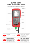
KANE450 QUICK REFERENCE GUIDE
INSTRUMENT FEATURES AND KEYPAD
Infra-red printer emitter
and torch light
Socket for gas
leak detector
Line select LED’s
Menu controls ~
Scroll up/down
Enter
Function buttons x 4
(See below for details)
Rotary switch
Particle filter
Water trap
“Battery charging” indicator
Analyser connections
Flue gas inlet
(See diagram overleaf)
PUMP / CAL PRESSURE
ON / OFF
Turns the pump ON / OFF
Turns the analyser ON / OFF
Press for 2+ seconds to zero
the pressure sensor
PRINT / BACKLIGHT
LINE SELECT / FREEZE
Press to print “live” or “frozen”
data. Press again to abort.
Press to select active line on
display as indicated by LED’s
Press for 2+ seconds to switch
backlight & torch ON / OFF
Press for 2 seconds to “HOLD”
Press longer to “LOG”
Supplied By www.heating spares.co Tel. 0161 620 6677
Temperature connections ~
Flue probe temperature (T1)
Inlet temperature (T2)
Battery charger connection
Flue gas inlet
Pressure connections ~
P1
P2 (differential)
Water trap drain
with rubber plug
BEFORE USING ANY ANALYSER CHECK THAT:
-
Calibration date has not expired
Particle filter is not dirty inside
Water trap and flue probe hose are empty of water
Water trap is fitted correctly to the instrument including the drain plug
Flue probe hose is connected properly to the flue gas inlet
Flue probe temperature plug is connected into T1 connection
Please read the Safety Warnings in the User Manual
USING THE ANALYSER
With the flue probe in fresh air at the same temperature as the boiler inlet air
. The analyser will auto-calibrate for 20 to 30 seconds and then a
press
set of readings will be displayed. In fresh air the O2 reading should be
20.9% + 0.1% and the CO reading should be zero. Check the battery status
by selecting “Bat” on the rotary switch and select the correct fuel via the
“menu” – See Using the Menu.
Insert the tip of the probe into the centre of the flue. After approximately 60
seconds the readings should stabilise. A printout can be produced if required
.
by pressing
SETTING UP THE DISPLAY
to move
Any four parameters can be displayed simultaneously. Press
the line select LED to the line you wish to change, then use the rotary switch
to select the new parameter you require. To change other lines just repeat
the procedure.
Supplied By www.heating spares.co Tel. 0161 620 6677
USING THE MENU
Select “Menu” on the rotary switch and navigate using the function buttons…
= Scroll up
= Scroll down
= Enter
MAIN MENU
SUB MENU
OPTIONS / COMMENTS
SETUP
SET FUEL
NAT GAS, L OIL, PROPANE, BUTANE, LPG, PELLETS
N
C
G
STORE
Uses “Military” time. 7am = 07:00, 7pm = 19:00
SET DATE
UK users, select DD-MM-YY then set the date
C
°C, °F
F
MG
SERVICE
PPM, MG/M3 (UK users should set to PPM)
O2 REF
NO, YES (UK users should set to NO)
LANGUAGE
various languages
SMOOTH
OFF = fast response. ON = slow response
RESOLVE
HIGH, LOW, selects the number of decimal places
PS UNITS
mBar, mmH2O, Pa, kPa, PSI, mmHg, hPa, InH2O
VIEW
View logged readings
AUTO STO
See KANE 450 REPORTS page
DEL ALL
NO, YES
REPORT
SCREEN
N = nett eff, G = gross eff, C = for condensing boilers
SET TIME
PPM
PRESSURE
Select the combustion efficiency calculation required ~
See KANE 450 REPORTS page
CONTRAST
Factory setting is 04
AUX
UK users normally set to display the current fuel type
HEADER
Sets printout header, 2lines, 20 characters per line
CODE
Leave set at “0000”
To EXIT the MENU at any time simply move the rotary switch to any position
other than “Menu”. Any changes that have not been “entered” will be ignored.
Supplied By www.heating spares.co Tel. 0161 620 6677
KANE450 REPORTS
TEST
11
DATE
TIME
03/08/05
16:27:32
AUTO STORE ~ (stores up to 255 tests)
FUEL
From the menu select STORE, AUTO STORE, YES.
Set the time interval (in seconds) between logs.
The analyser starts logging as soon as you exit the menu
and stops when you select STORE, AUTO STORE, NO.
O2 %
CO2 %
CO ppm
FLUE °C
INLT
°C
NETT °C
9.3
6.6
21
148.6
-OC125.8
EFF (N)
PRS mBAR
LOSSES %
XAIR %
92.5
0.001
7.5
80.1
CO/CO2
0.003
To view the results select STORE, VIEW, then enter the
log number required. Use the rotary dial and line selector
to view the readings as normal. Use scroll up/down to
view other log numbers.
To delete select DEL ALL, YES
NATU GAS
etc.
PRESSURE ~ (stores up to 8 tests)
TIGHTNESS TEST
From the menu select REPORT, PRESSURE, TEST.
LOG 05
TIME 15:40 03/08/05
Press the “Pump” key to zero the pressure sensor.
CONNECT the pressure hose to pressure connection P1.
Press “Enter” to start the 1 minute stabilization period.
Press “Enter” again to start the 2 minute tightness test.
To view the results select REPORT, PRESSURE, VIEW.
Use scroll up/down to view other log numbers.
PRS_1 mBAR
20.110
PRS_2 mBAR
19.998
DURATION MINS 3:00
…………………………………..
Customer
To exit press “Enter”. To delete select DEL ALL, YES
…………………………………..
Appliance
etc.
TEMPERATURE ~ (stores up to 8 tests)
TEMP TEST
From the menu select REPORT, TEMP, TEST.
CONNECT the thermocouples, “flow” to Tf, “return” to Ti.
Press “Enter” once to view readings and once more to log.
LOG 02
TIME 16:37 03/08/05
To view the results select REPORT, TEMP, VIEW.
Use scroll up/down to view other log numbers.
FLOW
°C
RETURN °C
NETT
°C
48.3
39.7
8.6
etc.
To exit press “Enter”. To delete select DEL ALL, YES
ROOM CO ~ (stores up to 8 tests)
ROOM CO TEST
From the menu select REPORT, ROOM CO, TEST.
The pump will run and the analyser will log the CO reading
every minute for 15 minutes.
LOG 01
TIME 09:20 04/08/05
To view the results select REPORT, ROOM CO, VIEW.
Use scroll up/down to view other log numbers.
Use “Enter” to view each reading within the ROOM CO
TEST
TEST
CO ppm
0
00
1
02
14
02
15
01
MAXIMUM CO
02
etc.
To exit use rotary switch. To delete select DEL ALL, YES
To print a displayed REPORT hold the “Print” key for 2+ seconds.
Stock No: 18326-2
Supplied By www.heating spares.co Tel. 0161 620 6677