1
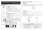
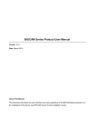
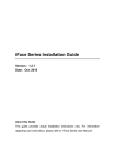
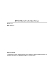
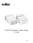
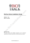
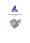
Chapter 1: The Installation of Device BIOCAM Series Product Installation Guide Version: 1.0 Date:2014.3 1. Install Device l Wall Mounting 1. Attach the installation template to the wall where you want to mount the camera and drill holes. (The Mounting Paper is 2.4 Precautions meters off the ground; according to needs, you can adjust it to l DO NOT connect cables when the power is on. 2~2.5 meters) l Working Conditions 2. Fix the camera on the wall using four screws. (The device can be Operating temperature: 10 ºC ~50 ºC. Operating humidity: 10% ~80%. l rotated left to right so that screws can be conveniently fastened.) Communication Distance l Top Mounting When communication distance exceeds 80 meters, please use relay device. 1. Connect the steeve to the device (Rem arks: under the POE[Optional] mode, if transmission distance is greater than 60 meters, 2. Attach the steeve mounting paper onto the wall or ceiling where please use a repeater.) l Keep the lens clean. If the lens is too dirty, use a tidy and soft cloth to clean the lens. l Do not point the camera against an object emitting strong light for a long time. the device will be installed. Drill holes according to marks on the steeve mounting paper 3. Use screws to fix the steeve Otherwise, the image sensor of the camera may malfunction, which leads to absence or 4. Adjust the length of the steeve to ensure that the Face distortion of images. Recognition Camera is 2.4 meters off the ground. (Note: according JTips: The product is applicable only to indoor installation. Do not install the device to needs, you can adjust it to 2~2.5 meters JNote: The steeve is not included in the standard configuration. outdoors; otherwise, the warranty is not granted. l Power Requirement The device supports three types of steeves that are respectively 40 The power must be DC 12V, rated current >= 1.5 A. l All uncovered cable should be less than 5mm, to avoid exceptional device damage. Recommended horizontal distance from the user to face recognition camera is about 3 cm to 60 cm, 60 cm to 80 cm, and 80 cm to 120 cm long. 2. Adjust the camera to the best angle meters. (Applied to height range 1.5~1.9m) After successful installation of the device, adjust the camera to the best l angle to implement face recognition and video surveillance. Detailed Suggest Condition Install the device indoors at least 10 feet (3m) away from windows, and 6.5 feet (2m) away adjustment methods are as follows: from light fixtures. Preferable light intensity should range between 0~800 LUX (1) Press the [F8] key on the Remote Control and the Auto Test interface l appears. The area in which face recognition can be implemented is defined as follows: the lefttoright distance is about 0.35 m, and the fronttorear distance is about 1 m. (For details, (2) The angle adjuster stands with an about 3 meters' horizontal distance see Appendix > Face Recognition Area) from the Face Recognition Cam era. (Note: That the adjuster must be about 1.7 meters high.) l Installing positions that affect the use effect of the device (3) Rotate the device up, down, left, and right to ensure that the facial image display inside the green box on the Auto Test interface (as shown in the figure on the right); that is to adjust the camera to the best angle. ?Note: (1) l Reference luminance of the light source in the installation environment In order not to affect the effects of the device and to prevent repeated disassembly of the device, ensure that you connect the device after the camera angle of the device is adjusted to the opium position. (For details about how to connect cables, see Chapter 2 and 3 in this guide.) (2) Users can adjust the human face parameters of the device according to the actual installation scenario and requirements. These parameters include the 1:1 matching threshold, 1: N matching threshold, exposure, and quality. For details about how to set these parameters, see the BIOCAM Series Product User Manual in the CRROM that is delivered with the device. 10Lux 1200+ Lux 50800Lux ‐1‐ ‐2‐ Chapter 2: Function Connection Diagram 3. Wiegand Input The device has W iegand input function, can connect the external card reader. Device and card reader can be installed respectively inside and outside of the door, control the lock together, control out & in. (1) The distance between device and access controller or card reader Access Control Function Intro: ① When a registered person is verified; the device will output a signal to shouldn’t be over 90 meters (If a longer distance is needed or there is interference in using environment, please use Wiegand signal delay.) open the door. (2) To ensure the stability of the Wiegand signal, the device must share the ② Connect Door Sensor. ③ Can connect an external Exit Button. Convenient to open the door GND with controller or Wiegand reader. from the inside. Chapter 4: Device Communication ④ Can connect an external Card Reader. ⑤ Use the ZKiVision Client software to manage multiple devices via The device has two types of communication methods to communicate with PC software. Exchange data and remotely manage. TCP/IP to network with PC. ① Connection between device and PC via twisted pair cable. ⑥ Can connect a Sound Box for voice play. Chapter 3: Connection Terminal 1. Connect the device to network and power on it. 1. The intro for device terminals 2. Change the IP address for PC to make sure the PC and the device's IP address are in the same network segment. 3. Run the browser. Enter the device's IP address (for example, Power interface: Connected to the standard power adapter. Do not use other power supplies; otherwise, the device may be damaged. http://192.168.1.88) in the address bar, and press Enter key to enter the Login interface. Network interface: It is a 10/100M selfsensing Ethernet interface, through which the device can be connected to various network devices, such as switches, routers, or hubs. 4. Enter the User Name and Password and click [Login] button to enter the Preview interface, then plays the realtime videos collected by the camera. Audio output: Connects with external play devices (such as Sound Box) to realize broadcast function. Reset button: Long press this button for more than 5 seconds when ?Notes: power on for 40 seconds, the camera will recover to default configuration. (1) If you use a browser to access the device for the first time, you need to download and install the ActiveX (ActiveXPlugin.ocx). Enter the device's IP address in the Address Bar and press Enter 2. Connect with Lock key, the ActiveX download window will popup. Then follow instructions displayed on the ActiveX download window to download and install the ActiveX. For details about how to use a The device can connect with NC or NO lock by connecting to the browser for video surveillance, see the Web Server User Manual, corresponding terminal. For the lock is open when power on and close which is available on the disk delivered with the device. when shut down, please use NO terminal. For the lock is close when (2) Configure the IP address before installing the device. For more power on and open when shut down, please use NC terminal. (Note: information, please see the BIOCAM Series Product User Manual Device and lock don’t share power supply.) on the disk delivered with the device. ‐3‐ ‐4‐ ② LAN Connection l Chapter 5: Appendix Enrolling Card (1) On the Add User interface, press [q] key on the Remote Control to move the cursor on the Card button, and then press 1. Instruction of Remote Control keys [OK] key to access the Enroll Card interface, Menu key [F8] key: Press it to enter the (2) The [Punch Card!] interface pops out as shown in Figure 3. Auto Test interface. Swipe your ID card properly in the swiping area. : Shortcut key for Add user p: Up q: Down t: Left u: Right (3) If the card passes the verification, the device displays a prompt message “Read Successfully! Card No.: **********”, as shown in [OK]: Save and Confirm key Return and Cancel key Backspace and Delete key T9 Input Keypad, Numeric Keys (0, 1, [*] key: Input “.”; switch T9 Figure 4, and returns to the Add User interface. 3. Verification Modes l 2, 3, 4, 5, 6, 7, 8, 9) 1: N Facial Verification (1) Compare the facial in a proper way. (Same as enrolling Face) input type. Place the face in the area in which the camera can capture images, [#] key: Press this key to input space. the device automatically distinguishes face verification (2) Comparison of interface display the current image collected by JTips: If the device is in dormant state, you can press any key on the Remote Controll to wake up the device. the camera. If the verification is successful, an interface as shown in Figure 5 will display. 2. Add User l Press 1: 1 Facial Verification key on the Remote Control to enter the Add user interface, shown as Figure 1: (1) Punch a registered ID card on the card reader in the correct Face: Enroll a user’s face. way. User ID: Enter a user ID. 1 to 9digit user IDs are supported by (2) After card authentication is passed, the system enters the 1:1 default. face image authentication mode. At this time, the face image on the ID card: Enroll a user card. interface is highlighted and a prompt "1:1" is displayed, as shown in Role: Set the rights of a user. A user is set to (Ordinary) User Figure 6. by default and can also be set to Administrator. (Ordinary) (3) Compare the facial in a proper way. Comparison of interface Users are only granted the rights of facial verification, while display the current image collected by the camera, as shown in Adm inistrators are granted the access to the main menu for Figure 5. various operations apart from having all the privileges granted to JTips: For details about how to use the device, see the BIOCAM Series Product User Manual, which is (Ordinary) Users. available on the disk delivered with the device. l 4. Product Appearance and Face Recognition Area Enrolling Face (1) On the Add User interface, press [OK] key to enter the Face l l Product Appearance enrollment interface. Surveillance camera (2) According to the prompt appears on the device’s screen (Focus eyes in box, shown as Figure 2). During face registration, you need to move from back to front to adjust the position of eyes. Display the face in the centre of screen as Face Recognition Camera possible. (3) If your facial image is enrolled successfully, the system will display a prompt message and automatically return to the Add Infrared receiver: Receives signals User interface. from the Remote Control. ‐5‐ ‐6‐ Face Recognition Area