1
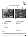
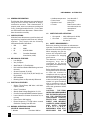
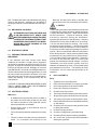
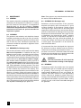
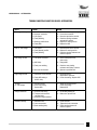
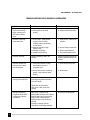
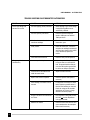
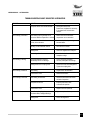
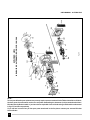
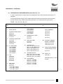
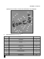
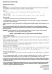
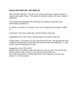
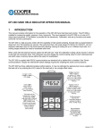
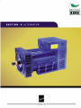
USER MANUAL - ALTERNATOR
SECTION E
INDEX
Alternator Illustrations
3
1.
General Information
4
2.
Safety Requirements
5
3.
Electrical Checks
6
4.
Safety
6
5.
Do’s & Don’ts
6
6.
Voltage Setting
7
7.
Maintenance
8
8.
Brushless - Exploded Illustrations
11
9.
Brushtype - Exploded Illustrations
13
E-3
USER MANUAL - ALTERNATOR
NOTES
.......................................................................................................................................................
.......................................................................................................................................................
.......................................................................................................................................................
.......................................................................................................................................................
.......................................................................................................................................................
.......................................................................................................................................................
.......................................................................................................................................................
.......................................................................................................................................................
.......................................................................................................................................................
.......................................................................................................................................................
.......................................................................................................................................................
.......................................................................................................................................................
.......................................................................................................................................................
.......................................................................................................................................................
.......................................................................................................................................................
.......................................................................................................................................................
.......................................................................................................................................................
.......................................................................................................................................................
.......................................................................................................................................................
.......................................................................................................................................................
.......................................................................................................................................................
.......................................................................................................................................................
.......................................................................................................................................................
.......................................................................................................................................................
.......................................................................................................................................................
E-4
USER MANUAL - ALTERNATOR
KIRLOSKAR GREEN ALTERNATORS
3
4
1
2
5
2
3
1
7
5
8
4
Fig. E-1
Fig. E-2
KG BRUSHLESS ALTERNATOR
KG BRUSH TYPE ALTERNATOR
1
End Cover
1
DE Shield
2
NDE Vent Cover
2
Slotted surround cover
3
Terminal Board and Rectifier Diode Assly.
3
Shaft
4
Terminal Box Cover
4
Fan
5
Compound Assembly of Fan and
Exciter Rotor-Stator
5
Eye bolt
6
Terminal box with LID
7
Excitation (CX) Unit
8
Magnet Frame (Body)
6
NOTE :
Depending on which alternator you have in your KGPI genset (please refer our sales office / service dealer) you
must refer the illustrations of the same shown above. Only the user serviceable parts are illustrated on the
surface of both the alternators above.
E-5
USER MANUAL - ALTERNATOR
1.0
•
•
•
•
GENERAL INFORMATION
The Kirloskar Green Alternators are manufactured
using the most accurate methods of design,
construction and test. Their characteristics, if
properly used, ensure a continuous working and
a very prolonged trouble free life. For the best
use of Kirloskar Green Alternators. Please follow
these instructions carefully.
1.1
SPECIFICATIONS :
Kirloskar Green Alternators are self excited, self
regulated and supplied with Electronic Voltage
regulator. They comply with the following
International/Indian Standards :
1.2
1.3
1.4
E-6
•
ISO
:
9001
•
BS
:
5000
•
IS
:
4722 & 13364
•
CSA
:
Canadian Standard
Association (1995)
MECHANICAL FEATURES
• Low Weight.
• Very Compact.
• Steel Body & C.I. End Shields.
• Life Lubricated Sealed Ball Bearings at both
the ends.
• Screen Protected: IP 20 (S).
• Optional: IP 21 (S), IP 23 (S) & IP 44 (S) can
be provided.
• Self Ventilated.
• Rotating Parts are Dynamically Balanced.
ELECTRICAL FEATURES
• Single / Three Phase, 240 Volts / 415 Volts
output at 50 Hz.
• Class ‘F’ Insulation.
• Steady State Voltage Regulation of ±5%.
• Current Compounded Self Excitation System.
• Lower Harmonic Content of less than 3%, at
no load.
• Power Factor 0.8 Lagging.
• Phase Sequence is U-V-W when rotated
Clockwise viewing from DE side.
NORMAL OPERATING CONDITIONS
(AS PER IS 13364 & IS 4722)
• Altitude
Less than 1000 m.
1.5
Less than 40° C.
0.8 Lagging.
I500 r.p.m.
Rated current value
as mentioned in the
nameplate of
alternator
LIMITS FOR SAFE OPERATION :
•
•
2.0
Ambient temperature
Power factor
Speed on load
Current
Over speed : 20% (1800 rpm for 50 Hz)
Over load
: 110% of rated value
for one Hr.
SAFETY REQUIREMENTS :
Before any cleaning, lubrication or maintenance
operation, ensure that the genset is stationary and
disconnected from the power supply.
While stopping the gen-set,
ensure the compliance with
the procedure for stopping
prime mover.
The alternator, in fact has no
emergency stop, but is
controlled by the device
arranged by the installer to stop
the prime mover.
Before installing the alternator,
arrangements must be made
to earth the machine in
compliance with any relevant
electrical regulations. This is
the reason why installer must
make sure that the grounding
system is in good conditions
and in compliance with the
regulations of the country
where the generators will be
installed.
CAUTION : THE FINAL
INSTALLER IS RESPONSIBLE
FOR THE INSTALLATION OF
ALL THE PROTECTIONS
(SECTIONING DEVICES;
PROTECTION
AGAINST
DIRECT AND INDIRECT
CONTACTS, OVER CURRENT
AND
OVER
VOLTAGE
P R O T E C T I O N S ,
EMERGENCY STOP ETC.)
NECESSARY FOR THE
STOP
USER MANUAL - ALTERNATOR
MACHINE TO COMPLY WITH THE EXISTING INTERNATIONAL SAFETY REGULATIONS.
For handing the unpacked alternators, always use the
special eyebolts only, use
ropes having a suitable
carrying capacity and do not
lift the alternator too much
from the floor (max. 30 cm.)
The operators in charge of
the installations, operation
and maintenance of the gensets must be skilled technicians who know the
characteristics of the gen-sets.
No person must wear fluttering cloths (such as scarves
etc.) near the machine and any such garment must
be fastened with elastic bands at its ends.
Alternator must never and for no reason be run with
following guards removed :
•
•
•
The operator must always wear work gloves and safety
shoes. In case the alternator or whole DG-SET must
be lifted from the floor, the operators must wear a
safety helmet.
Make sure that the gen-set foundations and base frame
are suitable to bear the combined weight of the
alternator and prime mover.
Terminal box cover
Rear cover
Fan ventilation guard
Alternators produce heat proportional to the output.
Therefore do not touch it if you do not wear antiscorch
gloves, and after switching it off, do not touch it until
it has cooled down.
Even if all machine components are protected, keep
away from the gen-set. Do not lean or sit on the
alternator for whatever reason.
2.1
DANGER OF SHORT CIRCUIT
The degree of protection of the alternator is IP21. Short
circuit may occur if liquids (e.g. water etc.) are split
onto areas containing electrical parts.
2.2
The alternator should be securely connected and
perfectly aligned with the prime mover, otherwise
dangerous vibrations may occur resulting in alternator
bearing failure.
All the instrumentation for starting, running and
stopping the system shall be provided by the installer.
THE STARTING, RUNNING AND STOPPING
OPERATIONS MUST BE CARRIED OUT BY SKILLED
PERSONNEL WHO HAVE READ AND UNDERSTOOD
THE SAFETY INSTRUCTIONS AT THE BEGINNING OF
THIS MANUAL.
2.3
The machine has been designed to ensure the rated
output when it is installed in a room having a max.
temperature of 400C and at an altitude not exceeding
1000 meters; in case of deviations please make
reference to our technical leaflets.
STARTING AND STOPPING OPERATIONS:
CLEANING :
Prior to approaching or touching the alternator, ensure
that it is not live and it is at room temperature; at this
stage it is possible to clean it on the out side using
compressed air.
NEVER USE LIQUIDS OR WATER FOR INSIDE
CLEANING.
E-7
USER MANUAL - ALTERNATOR
N.B. : The alternator frame is provided with many fixing
holes so that vibration - damping may be applied in
the proper position to ensure the best trim of the genset.
3.0
MECHANICAL COUPLING :
ALTERNATOR FOOT FIXING ON THE DE SIDE
IS ON END-SHIELD FOOT. HENCE CARE
MUST BE TAKEN WHILE CLOSING THE VENT
COVER AFTER TIGHTENING THE BOLT THAT
NO MATERIAL SHOULD BE LEFT OUT INSIDE,
WHICH MAY CAUSE DAMAGE OF FAN
UNDER OPERATION.
4.0
ELECTRICAL CHECKS
4.1
CHECKING THE INSULATION
RESISTANCE
If the alternator has been stored under damp
conditions or has taken a lengthy time in shipment,
the insulation resistance should be checked. For this
purpose, all external connections and neutral to earth
link if any should be removed. A Megger of not more
than 500 Volts D.C. should be connected between any
one AC output terminal and the magnet frame. In case
the test reveals the insulation resistance to be less
than 2.0 mega ohms (IR value at room temperature),
identify the winding or the component by step by
step isolation.
CAUTION: IF THE INSULATION RESISTANCE IS LESS
THAN 2 MEGA OHMS THEN THE ALTERNATOR
SHOULD NOT BE OPERATED.
4.2
ELECTRICAL CHECKS :
Make sure :
•
A suitable electrical protection device is fitted in
the output circuit for safety reasons (in line with
the codes of practice in force within the country
where the alternator is installed)
•
Ensure before start up that terminal nuts are
properly tightened.
•
The control panel protection equipment is correctly
set.
•
There is no short circuit due to wrong connections
either / or in between the terminals of the
E-8
alternator and the power switch or breaker (this
part of the circuit is not protected by the breaker).
5. SAFETY
• Basic safety precautions should always be followed
to eliminate fire, electric shocks or personal injuries.
• Always remember safety first. • Read and understand
all the instructions. • Follow alt warnings, safety
precautions necessary during the installation,
operation & maintenance of the alternator. • Cleaning
should be done only when the DG set is not running.
• Do not use damp cloths for cleaning. • Do not use
any liquid or aerosol cleansers. • Use only the eyebolt
provided for lifting the alternator. Incorrect lifting or
moving may result in equipment damage or personal
injuries. • Do not overload the cables as it may lead to
fires or electric shocks. • Never insert any objects inside
the alternator as it may lead to fires or electric shocks.
• Do not spill any liquid on the alternator. • Removing
the cover of the alternator while it is running will
expose you to the dangers of high voltages. • Incorrect
reassembly can cause electric shocks when the
alternator is subsequently used. • Ensure that the field
pole fasteners are not loose. • The earthing for body
of alternator and for neutral should always be as
specified.
6.
DO’S and DON’T’S
DO’S
1.
2.
3.
4.
5.
6.
7.
8.
9.
Tighten the foot mounting bolts.
Ensure that the alternator is properly grounded.
Ensure the tightness of the terminal bolts.
Ensure the crimping of lead wires.
Check the fuse if provided.
The body and neutral earthing should be perfect.
All protection gears should be used as required.
The rating of generator should match the load.
Ensure that the brushes are fully bedded centrally
on the slipring.
10. Check the free movement of the generator shaft
by lifting the brushes.
11 . Check the spring pressure.
12. Check the voltage during commissioning.
13. Check the phase sequence during installation.
14. All covers and guards should be fitted before
starting the generator.
USER MANUAL - ALTERNATOR
15.
After servicing the generator, make sure the
connections are as per connection diagrams.
16.
If the lifting of the alternator is necessary then lift
using eye bolts only as shown in the figure.
17.
Maintain and operate the generator correctly.
18.
Run the DG set daily for at least 5-10 minutes on
no load.
7.0
VOLTAGE SETTING AND ROTATING SPEED :
The output voltage of the alternator should be
checked at rated speed 1500 R.P.M.
Usually the alternators are preset at the factory
to supply voltage slightly higher (from 3 to 5%)
than the nominal one at rated speed. In Frame
G2R/160/200/250/280 if one want to regulate the
no load voltage of the alternator at determined
rated speed it is necessary to operate.
7.1
REMOTE REGULATION OF THE VOLTAGE:
(In Frame G2R 160/200/250/280/315)
Remote regulation of the voltage is obtained by
mounting a 100 KΩ potentiometer between the
terminals 5 and 7 permitting a regulation of +
5% of the nominal voltage.
WARNING : FOR THE ALTERNATOR
GOOD WORKING IT IS ADVISABLE NOT
TO DEVIATE FROM THE NOMINAL
VOLTAGE MORE THAN 5%
Fig. E-3
7.2
ELECTRICAL FAILURE TROUBLESHOOTING
DON’T’S
1.
Don’t operate the machine with higher current
than the nameplate current
2.
Don’t operate the machine at less than 0.8 power
factor within deration
3.
Don’t start the machine with load.
4.
Don’t operate the generator without the covers.
5.
Don’t block the air inlet and outlet of the machine.
6.
Don’t have excessive wiring lengths at the
application end.
7.
Don’t expose the generator to moist condition.
8.
Don’t use low grade cables.
9.
Don’t operate the alternator if the IR value is found
to be less than 2 mega ohms.
10.
Don’t apply capacitive loads.
12.
Don’t run the machine with the field pole fasteners
loose.
When an electrical failure occurs, check for
trouble as explained below :
1)
In order to find out if the failure has
happened in the alternator itself or in the
regulation system one has to test the
alternator at no load (at nominal speed)
exciting the exciter stator directly, using an
external dc source.
When applying the voltage to the exciter
stator one has to comply with polarities :
apply the negative polarity of the auxiliary
source to the negative terminal and positive
terminal to the positive terminal of the exciter
fields.
Verify that :
A)
When feeding the winding according
to the excitation data at no load (listed
in the table) the voltage supplied by
the alternator is almost the rated one
B)
After the localization of fault, repair
properly.
E-9
USER MANUAL - ALTERNATOR
8.
MAINTENANCE
8.1
GENERAL
The machine should be completely isolated from all
electrically live wires before any electrical or rotating
part of it is touched. The frequency of maintenance
depends largely on the site conditions. Frequent
maintenance of approximate once a week should be
practiced at first and the period extended as
experience is gained.
8.2
CLEANING
The generator and excitation unit should be cleaned
internally by blowing out with a jet of dry air and by
wiping away any deposits of grease and carbon dust
with a clean dry cloth. All fasteners especially the
connectors should be inspected for tightness at less
frequent intervals.
8.3
BRUSHES (For Brushtype only)
The brushes should be closely examined after every
500 hours of operation to establish that they are
bedded properly and are not sticking in their holders
and that the correct brush pressure is being
maintained. Brushes should be replaced with genuine
spares before they wear down to 10mm in length.
New brushes must be bedded by placing a piece of
fine carborundum cloth between the brushes and the
slipring with the abrasive side towards the brushes
and high application of spring pressure. The cloth
should be drawn forward and backward under tension
so that it follows the curvature of the slipring. This
operation should be finished by several strokes in the
direction of rotation, lifting the brushes during the
return stroke. It is essential that all carbon and abrasive
particles be removed by a jet of dry air and by wiping
with a clean and dry cloth. During bedding the adjacent
winding should be masked to prevent entry of carbon
dust. The pressure on each brush should be checked
and adjusted to 200-250gms per square cm.
E-10
Note: Emery paper or any other abrasive should never
be used to clean bedded brushes.
8.4
SLIPRINGS (For Brushtype only)
Satisfactory electrical operation of the generator
depends principally upon maintenance of good
working condition of the sliprings. During normal
running the rings should have a dark burnished
appearance without grooving or uneven wear. During
periodic maintenance the sliprings and the grooves
between them should be cleaned. If any signs of wear
or blackening are observed the spring pressure
should be checked and readjusted if required. If
blackened badly, the rings should be polished by
running the machine and using a fine carborundum
or emery paper. This operation is to be carried out
with the brushes lifted.
If pronounced flats have developed the rings must
be skimmed, brushes bedded and the machine
cleaned out by blowing compressed air before it is
put back in to service. The brush holders should be
positioned on the spindle so as to let the brushes ride
on the centre of the width of the sliprings.
WARNING :
The field connections Fl & F2 should be
removed before working on the sliprings.
8.5
BEARINGS
The bearings used in the machine are from reputed
manufacturers and are of sealed type thus requiring
no greasing. The bearings are designed for
approximately 40,000 hours of use and should be
replaced after that. However in case high bearing
noise is observed or leakage of grease noticed it is
strongly recommended that the bearing be checked
and replaced immediately to prevent failure during
running as this could cause irreversible damage to
the generator.
USER MANUAL - ALTERNATOR
TROUBLE SHOOTING CHART BRUSHLESS ALTERNATORS
FAULT
CAUSE
REPAIR
No voltage build - up
1)
2)
3)
4)
1)
2)
3)
4)
Insufficient residual voltage
Improper connection
Low speed
Faulty Winding
Excite the rotor using a battery
Correct the connection
Reset the speed to the nominal
Check the winding resistance
and rewind if required
Replace the rotating rectifier
Replace the AVR
5) Rotating rectifier failure
6) Faulty AVR
5)
6)
Low no - load voltage
1) Low speed
2) Faulty Rotating rectifier
3) Faulty Winding
1)
2)
3)
Reset the speed to the nominal
Replace the rotating rectifier
Check the winding resistance and
rewind if required
Low voltage on load
1) Low speed at full load
1)
2) AVR faulty
2)
Set the rated speed of the
prime mover
Change AVR
3) Faulty rotor winding
3)
4) Over load on alternator
4)
1) Capacitors on the load side
1)
2) Faulty AVR setting or
AVR is faulty
2)
Too high
no - load voltage
1) Excessive speed
2) Correct the setting
Replace AVR
1)
Adjust the revolving speed
Correct the setting
Replace AVR
Voltage oscillations
1) Incorrect AVR setting
2) Thyristor load more than
specified limits
3) Insufficient engine flywheel
1)
2)
Set the AVR stability pot
Reduce the Thyristor load
Unbalance Voltage
1) Unbalance load
2) Loose connections
3) Stator winding faulty
1)
2)
3)
Correct the load
Tighten the loose connections
Check winding resistance &
rewind if required
High voltage on load
Check the rotor winding
resistance and if faulty, rewind it
Operate on specified load
Disconnect the PF
improvement capacitors
Correct the setting / Replace AVR
E-11
USER MANUAL - ALTERNATOR
TROUBLE SHOOTING CHART BRUSHLESS ALTERNATORS
FAULT
CAUSE
REPAIR
Excessive overheating
of one or both bearings
(temp. of bearings over
800C) (with or without
noise)
1) Set misalignment
2) Bearing loose in end shield
housing
1) Align the set properly
2) Replace the faulty End shield
Excessive overheating
of alternator frame
1) Air flow (inlet - outlet) partially
clogged or hot air is being
circulated either from alternator
or prime mover
2) Alternator operating at high
Voltage at load
3) Alternator overloaded
4) Load PF less than 0.8 lag
1) Check air inlet - outlets of the
alternator
2) Set the voltage to rated value
3) Operate at specified load
4) correct the load power factor
Excessive vibrations
Defective mounting or play in the
coupling
Replace the coupling & check the
alignment Reset the speed to the
nominal
Excessive vibration and
humming noise coming
from the alternator
1) Three phase alternator is single
phase loaded in excess of
acceptable limits
1) Check and correct the load
2) Start up with no-load : if humming
persists - faulty alternator stator
winding
2) Rewind stator
Short circuit in the external circuit
(including wiring between alternator
and control board)
Stop the set immediately
Smokes, spark or flames
coming from the alternator
Object fallen into the machine
short circuit or flash in the stator
winding
Alternator damaged by
a significant impact which
is followed by humming
and vibration
E-12
Short circuit in external circuit
Faulty parallel connection (out of phase)
Break or deterioration in the coupling
Break or twist in shaft extension
Shifting or short circuit of main field
winding
Bursting or unlocking of the fan
Diode burnt, rectifier bridge damaged
Stop the gen-set immediately
USER MANUAL - ALTERNATOR
TROUBLE SHOOTING CHART BRUSHTYPE ALTERNATORS
FAULT
CAUSE
REPAIR
No voltage from alternator
Open circuit in excitation unit
Check the continuity of excitation
transformer windings
Check rectifier Connections.
Wrong field connections
Check the positive terminal of the
rectifier (red wire) connected to F1
and the negative terminal (black wire)
to F2.
Open circuit in field winding
Check the continuity of the field
winding, if open connected the joint
that have been broken
Loss of residual magnetism
Check the residuaal voltage at the
alternator terminals. This should be
about 10 volts and balanced between
all the three lines.
Fault rectifier
After charging check voltage at the
terminals F1 & F2. If there is no D. C.
Voltage replace the rectifier (if in
doubt)
Faulty surge suppressor unit
Check the connections. F1 to positive
terminal (red) and F2 to negative
terminal (black)
Defective excitation capacitor
Check for short circuit or open circuit
of the capacitor, if faulty replace it.
Short circuit or open curcuit
in armature winding
Armature rewinding is necessary
Brushes not bedding properly
Check if the brushes are sticking in
boxes or if bedding is short proper. If
the brushes are found tight in the box,
just polish the faces of the brush with
emery cloth.
Check if brush holder leavers are in
locked position and the spring
pressure is even.
E-13
USER MANUAL - ALTERNATOR
TROUBLE SHOOTING CHART BRUSHTYPE ALTERNATORS
FAULT
CAUSE
REPAIR
Low or high voltage from
alternator on no load
Incorrect tappings (shunt) connected
Select tappings to get correct voltage
if voltage and regulation are not
satisfactorily obtained.
Incorrect speed of prime mover
Check the speed and adjust the
speed to 1560 rpm on no load and
1500 rpm on load
Unbalanced currents in excitation
transformer windings
Reset the excitation unit as per the
instructions given.
Faulty rectifier
Check the rectifier unit, if current in
excitation unit windings are balanced
and if the input voltage to the rectifier
unit is unbalanced, replace the
rectifier.
Turns shorted in the field coil
Check the faulty coil and replace it.
Incorrect speed of the prime mover
Adjust the speed of the prime mover
to correct value on no load and full
load. The speed should be 1560 rpm
on no load. On load the speed should
be uniform at 1500 rpm (Full load)
Load current are not balanced and
within the rated current
Adjust and reduce the load.
Open or short circuit in capacitor
Check the capacitor and replace if
necessary
Series winding of excitation unit are
reserved
If voltage falls excessively low when
load is applied, a possible reason is
that the series winding are reversed
Check the voltage at the terminals
and slipring unit, if there is a large
difference reconnect properly
Air gap of excitation unit transformer
not correct
If the regulation is marginally outside
the limits + 5% then adjustments
in air gap to be made.
Machine over loaded
Check the load current with the rated
current mentioned on the nameplate.
Reduce load if necessary.
Voltage regulation is
unsatisfactory
E-14
USER MANUAL - ALTERNATOR
TROUBLE SHOOTING CHART BRUSHTYPE ALTERNATORS
FAULT
Over heating of alternator
Over heating of bearing
Over heating of armature
Over heating of field coils
High vibrations
CAUSE
REPAIR
Low power factor of the connected load
Check power of the load.
Power factor equipment is necessary
if the power factor is lower than
rated p.f.
Over heating may be generally due to
excessive ambient temperature or altitude
Reduce load so that allowable
temperature are not exceeded
Re-circulation of hot air in the
vicinity of the alternator
Avoid re-circulation by erecting
external baffles
Blocking of inlet ventilation louvers
Clean for free air intake
Misalignment
Check the alignment and readjust it
Overloading of machine
Check the load and current with
nameplate ratings
Low speed/frequency incorrect,
reassembly of worn out bearings
Correct the speed, assemble
correctly and replace the bearings
Misalignment/Loose coupling bolts
Check and correct the misalignment
Tighten the coupling bolts
Over loading
Adjust load on the alternator
Internal short circuit
Rewind the armature
Over heating of alternators
Check the load current and reduce
the load of capacitors
Load power factor low
Improve power factor with
connection of capacitor
Internal short circuit
Replace field coils (shorted)
Loose/Broken Coupling, Loose
Foundation Bolts, Damaged Bearings
Tighten or replace the component
Misalignment
Correct the alignment
E-15
Fig. E-4
EXPLODED VIEW
BRUSHLESS ALTERNATOR G2R/G1R 160/200
USER MANUAL - ALTERNATOR
NOTE :
To carry out defective part replacement you may require spares mentioned in the Tables 9.0 and 9.1 as follows.
As these parts of an alternator can be seen only after dismantling the alternator (only let trained technicians/
Kirloskar Service Dealer handle it ), we have shown exploded views of the brush type and brushless alternators
in figs. E-5 and E-4 respectively.
If you still are in need of any of the spare parts mentioned in the list please contact your nearest Kirloskar
Service Dealer.
E-16
USER MANUAL - ALTERNATOR
9.0
DESIGNATION OF THE SPARE PARTS (Please Refer Fig. C-4) :
In case of replacements of spare parts use original spare parts only for the best performance of
alternator.
For the replacements of worn parts, carefully follow the maintenance instruction, these operations
must be carried out by skilled and trained technicians or our authorized service personnel.
FRAME : 160 / 200 / 250 / 280 / 315
PART DESCRIPTION
NO.
3
FRAME WITH WND PACK
4
ROTOR (Wound)
7
WOUND EXCITER STATOR
160 Frame
200 Frame
250/280 Frame
315 Frame
8
WOUND EXCITER ROTOR
160 Frame
200 Frame
250/280 Frame
315 Frame
PART DESCRIPTION
NO.
53
54
55
65
10a
47
51
D.E. END SHIELD
G1R 160/SAE3
G1R 160/SAE2
G1R 200/SAE3
G1R 250/SAE3
G1R 280/SAE1
G1R 315/SAE1
FAN
160 Frame
200 Frame
250 Frame
280 Frame
315 Frame
END COVER
160 Frame
200 Frame
T. Box ASBY G1R 250
T. Box ASBY G1R 280
T. Box ASBY G1R 315
66
302
D.E. VENT COVER
G1R 160/SAE 3
G1R 160/SAE 2
G1R 200/SAE 3
G1R 280/SAE 1
G1R 315/SAE 1
PART
NO.
325
COUPLING HUB
SAE 11.5 FOR G1R160 Frame
SAE 11.5 FOR G1R200 Frame
SAE 14 FOR G1R250 Frame
SAE 14 FOR G1R280 Frame
SAE 14 FOR G1R315 Frame
COUPLING DISC SET
SAE11.5 (Set of 2 Nos.) for G1R 160
SAE11.5 (Set of 3 Nos.) for G1R 200
SAE14 (Set of 4 Nos.) for G1R 280/31
N.D.E. BEARING
160 Frame - 6310.2RS
200 Frame - 6310.2RS
250 Frame - 6310.2RS
280 Frame - 6313.2RS
315 Frame - 6314.2RS
MAIN TERMINAL BOARD
WITH 6 TERMINAL
160 Frame
200 Frame
250 Frame
280 Frame
TERMINAL BOX COVER
160 Frame
200 Frame
NDE VENT COVER
160 Frame
200 Frame
DESCRIPTION
315 Frame
359
AUXILIARY TERMINAL
BOARD (3 TERMINAL)
G2R/G1R 160 Frame
G2R/G1R 200 Frame
371
DIODE BOARD ASSEMBLY
160/200/250/280 Frames)
315 Frame
386
AVR SR 7/3
AVR UVR - 6
MOV RDN 440/14 for roating
Rectifier
E-17
USER MANUAL - ALTERNATOR
CONSTRUCTIONAL FEATURES OF THE KIRLOSKAR GREEN BRUSH TYPE ALTERNATORS
Fig. E-5
9.1
PARTS DESCRIPTION (Please refer Fig. C-5)
PART NO.
DESCRIPTION
QTY.
1
MAGNET FRAME (BODY
1
2
POLE BRICKS
4
3
FIELD COILS
1 SET
4
EYE BOLT
1
5
EARTHING SYMBOL PLATE
2
6
ROTOR
1
7
ROTOR COILS
1 SET
8
ROTOR END PLATES
2
9
SHAFT
1
10
FAN KEY
1
11
SLIPRING ASSEMBLY
1
12
BRUSH HOLDER WITH BRUSHES
4 SETS
13
FAN
1
14
EXTENSION KEY
1 NO.
E-18
USER MANUAL - ALTERNATOR
PART NO.
DESCRIPTION
QTY.
15
CIRCLIP
1
16
DE BEARING CAP
1
17
DE BEARING
1
18
DE SHIELD
1
19
SLOTTED SURROUND
1
20
BRUSH HOLDER SPINDLE
4
21
NDE BEARING CAP
1
22
NDE BEARING CAP
1
23
NDE SHIELD
1
24
VENTILATION GIRDS
2
25
TERMINAL BOX WITH LID
1
26
EXCITATION (CX) UNIT
1
E-19
USER MANUAL - ALTERNATOR
NOTES
.......................................................................................................................................................
.......................................................................................................................................................
.......................................................................................................................................................
.......................................................................................................................................................
.......................................................................................................................................................
.......................................................................................................................................................
.......................................................................................................................................................
.......................................................................................................................................................
.......................................................................................................................................................
.......................................................................................................................................................
.......................................................................................................................................................
.......................................................................................................................................................
.......................................................................................................................................................
.......................................................................................................................................................
.......................................................................................................................................................
.......................................................................................................................................................
.......................................................................................................................................................
.......................................................................................................................................................
.......................................................................................................................................................
.......................................................................................................................................................
.......................................................................................................................................................
.......................................................................................................................................................
.......................................................................................................................................................
.......................................................................................................................................................
.......................................................................................................................................................
E-20