1
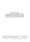
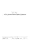
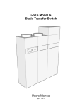
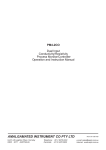
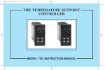
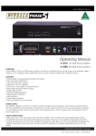
HH4-WT
Hand Held
Digital Load Cell/Pressure Meter
Operation and Instruction Manual
AMALGAMATED INSTRUMENT CO PTY LTD
Unit 5, 28 Leighton Place Hornsby
NSW 2077 Australia
Telephone: +61 2 9476 2244
Facsimile: +61 2 9476 2902
ACN: 001 589 439
e-mail: [email protected]
Internet: www.aicpl.com.au
Table of Contents
1 Introduction
3
2 Electrical connections
4
3 Function tables - summary of setup functions
5
4 Explanation of functions
7
5 External memory
18
6 Serial communications
20
7 Specifications
26
8 Guarantee and service
28
2 of 28
HH4WTMAN-3.3-0
1
Introduction
This manual contains information for the operation of the HH4-WT hand held load cell monitor.
The HH4 is suitable for measuring weight, pressure, force, torque etc. The input required by the
HH4-WT is a 4 wire mV/V output type transducer. 5V excitation is provided for the transducer.
Calibration, and set up functions are easily achieved via front pushbuttons.
The HH4 is a high accuracy meter with the capability of high speed sampling. Sample rate is
programmable in steps from 5 to 100 samples per second. The instrument has a full scale range of
0.5mV/V to 100mV/V. Up to 3 separate calibration sets can be stored internally allowing viewing
of scaling for up to 3 different load cells, or 3 scaling ranges without the need to recalibrate each
time.
When used with the external memory option the HH4 can “read” the calibration scaling values
stored in memory in the load cell connector shell. The instrument can then display the correct
scaling value for each individual load cell which uses a memory device without the need for recalibration.
The HH4 is supplied with RS232 communications as standard but by default this is disabled. See
“Serial communications” chapter for internal DIP switch settings required for enabling the serial
communications.
The HH4-WT has three calibration/scaling method options. It may be calibrated by applying two
know weights to the load cell or by entering the mV/V value for the load cell or via a single offset
value.
HH4WTMAN-3.3-0
3 of 28
2
Electrical connections
Power for the HH4 is provided by a 9VDC (216) battery. The battery cover is located at the
underside of the case. External connections to the HH4 are made via a 9 pin “D” male connector.
The HH4 provides 5VDC excitation for the mV/V output transducer. Electrical connections are
as shown below.
Refer to ”External memory” chapter for details of the optional external memory chip. Refer to
”Serial communications” chapter for details of the RS232 wiring connections.
4 of 28
HH4WTMAN-3.3-0
3
Function tables - summary of setup functions
Functions in this first table are available in FUNC or CAL mode, see page 7.
Display
Function
Range
Default
Your Ref/Page
record
CHNL
Calibration memory selection
CH1, CH2,
CH3 or CH.A1
CH1
4.1 / 8
drnd
Display rounding
1 to 5000
1
4.2 / 8
Unit
Memory chip address
1 to 250
255
4.3 / 8
dCPt
Decimal point place
0 to 0.003
0
4.4 / 9
FLtr
Digital filter
0 to 8
2
4.5 / 9
Functions in this second table are available only in CAL mode, see page 7.
Display
Function
Range
Default
RNGE
mV/V input range
0.5, 1.0, 2.5,
5.0, 10, 20,
40 or 80
2.5
4.6 / 9
RAtE
Sample rate in samples/sec.
5, 10, 15,
20, 30, 40,
50, 60, 80 or
100
10
4.7 / 10
USER
User pushbutton function
NONE, tArE,
d.HLD,
P.HLd, CHNL
or Prnt
NONE
4.8 / 10
CAL1
Live input calibration first point
Any display
value
n/a
4.9 / 11
CAL2
Second point for live input
calibration
Any display
value
n/a
4.10 / 12
ECAL
Alternative mV/V calibration
method
-1.999 or
9.999
1.000
4.11 / 13
CAL
OFSt
Calibration offset
Any display
value
n/a
4.12 / 14
ZERO
RNGE
Zero range limit
0.0 or 100.0
10.0
4.13 / 14
CAL
ZERO
Zero reference
n/a
n/a
4.14 / 15
SEt
ZERO
Display zero
n/a
n/a
4.15 / 15
CLr
ZERO
Clear zero
n/a
n/a
4.16 / 15
P.OFF
Power off time
0 to 300
10
4.17 / 15
HH4WTMAN-3.3-0
Your Ref/Page
record
5 of 28
bAUd
RAtE
Baud rate for serial
communications
300, 600,
1200, 2400,
4800, 9600,
19.2 or 38.4
9600
4.18 / 16
PrtY
Parity for serial input
NONE, EUEN
or Odd
NONE
4.19 / 16
O.Put
Output for serial
communications
dISP, Cont,
POLL or
A.buS
Cont
4.20 / 16
Addr
Instrument address for serial
communications
0 to 31
0
4.21 / 16
6 of 28
HH4WTMAN-3.3-0
4
Explanation of functions
The HH4 setup and calibration functions are configured through a push button sequence.
Two levels of access are provided for setting up and calibrating namely:• FUNC mode (simple push button sequence) allows access to calibration channel selection,
display rounding, decimal point and digital filter settings only.
• CAL mode (power up sequence plus push button sequence) allows access to all functions
including calibration parameters.
Once CAL or FUNC mode has been entered you can step through the functions, by pressing and
releasing the F push button, until the required function is reached. Changes to functions are
made by pressing the ^ or v push button (in some cases both simultaneously) when the required
function is reached. Any changes to a function will not be saved until the F button is pressed to
accept the change.
HH4WTMAN-3.3-0
7 of 28
Explanation of Functions
4.1
Calibration internal memory selection
Display:
Range:
Default Value:
CHNL
CH1, CH2, CH3 or CH.A1
CH1
Selects one of the three possible calibration internal memories (CH1, CH2, CH3, also CH.A1 if
the optional external memory chip is used - see chapter 4.23). The CHNL function allows the
instrument to be calibrated to up to 3 different load cells and hold the calibration values in internal
memory. Alternatively 3 different calibration scaling values may be entered for a single cell, allowing
the same cell to display in different units e.g. Kilonewtons, Kilograms and Tonnes. The user may
select the load cell to be used via this CHNL function or via the User pushbutton if the pushbutton
has been programmed for this purpose (see USER function). To scale any of these independent
calibration memories you may use either the CAL1/SCL1 and CAL2/SCL2 methods or the
ECAL/ESCL method. Simply select the required cell number prior to scaling then scale using
whichever calibration method best suits the application.
The channel selected will always default to CH1 (or CH.A1 if external memory is used) at switch
on. In addition to independent calibration scalings for each channel selected each channel can be
assigned different decimal point (dCPt), digital filter (FLtr), mV/V input range (RNGE) and
sample rate (rAtE) settings.
4.2
Display rounding
Display:
Range:
Default Value:
drnd
1 to 5000
1
Displays and sets the display rounding value. This value may be set to 1 - 5000 displayed units.
Display rounding is useful for reducing the instrument resolution without loss of accuracy in applications where it is undesirable to display to a fine tolerance. To set the display rounding value
go to the drnd function and use the ^ or v push buttons to set the required value then press
F to accept this selection.
Example: If set to 10 the display values will change in multiples of 10 only i.e. display moves
from 10 to 20 to 30 etc.
4.3
Memory chip address
Display:
Range:
Default Value:
Unit
1 to 250
255
This function is only seen when an external memory chip is connected. This function is used to
display or set a unit address to one or more optional external memory devices. For identification
purposes each device should be allocated a different address if more than one external memory is
used. When a sensor with a memory chip is plugged in the Unit function can be used to view
the address of the memory device. The address can be set from 1 to 250. If the default address
255 is seen this indicates that the device has not had yet had an address set. If a memory device
has had an address set then the address can be viewed or altered at this function. The procedure
8 of 28
HH4WTMAN-3.3-0
for setting or altering an address is as follows.
1. The CHNL function must be set to either CH.A1 i.e. a memory device must be connected.
2. With the external memory device connected enter function mode and step through to the
Unit function.
3. Use the ^ or v arrow to select the required address for that chip then press F to accept
the change.
The address selected will now be stored in that memory device. The same address can be allocated
to more than one memory device and the address of a device can be changed at any time by
following steps 1, 2 and 3 above.
4.4
Decimal point place
Display:
Range:
Default Value:
dCPt
0 to 0.003
0
Displays and sets the decimal point place. By pressing the ^ or v pushbuttons the decimal point
position may be set. The display will indicate as follows: 0 (no decimal point), 0.1 (1 decimal
point place), 0.02 (2 decimal point places) or 0.003 (3 decimal point places).
4.5
Digital filter
Display:
Range:
Default Value:
FLtr
0 to 8
2
Displays and sets the digital filter value. Digital filtering uses a weighted average method of
determining the display value and is used for reducing display value variation due to short term
interference. The digital filter range is selectable from 0 to 8, where 0 = none and 8 = most
filtering. Use ^ or v at the FLtr function to alter the filter level if required. Note that the
higher the filter setting the longer the display may take to reach its final value when the input is
changed, similarly the relay operation and any output options will be slowed down when the filter
setting is increased. To set the digital filter value go to the FLtr function and use the ^ or v
push buttons to set the required value then press F to accept this selection.
4.6
mV/V input range
Display:
Range:
Default Value:
RNGE
0.5, 1.0, 2.5, 5.0, 10, 20, 40 or 80
2.5
Displays and sets the mV/V range to suit the transducer useable range. Choose the value equal to
or the next higher value to the mV/V output of the transducer. This selection sets the input range
for the A/D converter. If too low a range is selected a “- - - -” error message will be seen on the
display. If too high a range is selected the full resolution capability will not be used and problems
with calibration can result.
HH4WTMAN-3.3-0
9 of 28
4.7
Sample rate
Display:
Range:
Default Value:
RAtE
5, 10, 15, 20, 30, 40, 50, 60, 80 or 100
10
Sample rate for ADC - Displays and sets the ADC sample rate from 5 to 100 samples per second.
The faster sample rates can be utilised in features such as peak hold and peak/valley memory.
4.8
User pushbutton function
Display:
Range:
Default Value:
USER
NONE, tArE, d.HLD, P.HLd, CHNL or Prnt
NONE
In normal measurement mode the User push button can be programmed to operate in one of the
modes described below. In CAL or FUNC modes pressing the User button will cause the instrument
to immediately return to normal measurement mode. Any changes to the function selected when
the button was pressed will not be saved. This function may be set to any one of the following:
• NONE - Button has no special function.
• tARE (Push button tare) - the pushbutton must be pressed for 2-3 seconds to perform a tare
operation. When tare is selected you can toggle between the nett, tare and gross displays via
the User pushbutton. The message GROS, NEtt or tARE will precede the measurement
value.
• d.HLd (Display hold) - Press the User button momentarily to hold the display, the message
HOLd will flash every few seconds. Press the F button to reset back to normal display. If
the User button is held pressed for 2-3 seconds the held value in memory will be reset and a
the current value will be held. The display will automatically reset to normal measurement
after 20 seconds. Holding the User button pressed in will cause the held value to be reset
and the value on the display after the reset will be held for as long as the button is pressed
down. The held display will only return to normal measurement 20 seconds after the button
is released.
• P.HLd (Peak hold) - Press the User button momentarily to hold the peak value display
the message P.HLd will flash every few seconds. Press the F button to reset back to
normal display. If the User button is held pressed for 2-3 seconds the peak value in memory
will be reset and a the current value will be become the new peak value. The display will
automatically return to normal measurement after 20 seconds. Alternatively if the User
button is held pressed down the peak reading will be held whilst the button is held pressed
down and will only return to normal measurement 20 seconds after the button is released.
• CHNL (Change calibration channel) - Allows toggling between input readings for calibration
channels CH.A1 (if memory chip is used) CH 1, CH 2 and CH 3. If switched off then the
instrument automatically reverts to CH 1 (or CH.A1 if memory chip is used) when switched
on again.
• Print (Output serial string to printer etc.) - The RS232 serial communications must be
enabled to use this function. With the USER function set to Prnt and the O.Put function
set to POLL each time the User button is pressed the display value will be sent from the
RS232 serial port in 8 bit ASCII format.
10 of 28
HH4WTMAN-3.3-0
4.9
First point for live input calibration
Display:
Range:
Default Value:
CAL1
Any display value
n/a
Two point calibration scaling - this is an alternative calibration method to the ECAL method of
scaling, note that only one method needs to be used (See “Use of ECAL and ESCL as reference
values” if using CAL1 and CAL2). The CAL1 and CAL2 functions are used to set two independent calibration/scaling points of the input to the display. This method uses two different live
input values to scale the instrument. The method is as follows:
1. Enter the setup functions via CAL mode and choose the required channel number at the
CHNL function. The channel number selected will be the channel for which this calibration
scaling operation applies.
2. Step through the functions by pressing and releasing the F button until the display indicates
CAL1.
3. Press then release, the ^ and v buttons simultaneously to enter the calibration functions.
4. The display will now indicate CAL1 (1st calibration point) followed by a “live” reading.
5. Apply a known input to the instrument of nominally 0% (this value is not critical and may
be anywhere within the measuring range of the instrument). For example you could arrange
that the load or pressure is zero at this time. When the live reading has stabilised press the
F button.
6. The display will indicate SCL1 (scale 1) followed by the scale value in memory.
7. Use the ^ or v button to obtain the required scale value.
8. Press the F button, the display will now indicate CAL End (indicating that calibration of
the first point is complete).
9. The display will now indicate CAL2 (2nd calibration point). If you do not wish to enter the
second point at this stage then press and release the F button until the FUNC End message
is seen. If you wish to enter the second point at this stage press the ^ and v buttons
simultaneously.
10. The display will now indicate CAL2 (2nd calibration point) followed by a “live” reading.
11. Apply an input of 100% (again this value is not critical, but there must be at least 10% of
rated capacity difference between CAL1 and CAL2 inputs. For best accuracy the difference
between CAL1 and CAL2 inputs should be as large as possible).
12. When the reading has stabilised, press the F button, the display will now read SCL2 (scale
2) followed by the second scale value in memory.
13. Use the ^ or v button to obtain the required scale value.
14. Press the F button, the display will now read CAL End (indicating that calibration of the
second point is complete). The display will now move to the next function.
Two Point calibration graphs
HH4WTMAN-3.3-0
11 of 28
Display value
Display value
SCL2
CAL1
CAL2
SCL1
Input
CAL2
CAL1
Setting CAL1
4.10
Input
Setting CAL2
Second point for live input calibration
Display:
Range:
Default Value:
CAL2
Any display value
n/a
Used to set the second live input calibration point, see CAL1.
12 of 28
HH4WTMAN-3.3-0
4.11
Alternative mV/V calibration method
Display:
Range:
Default Value:
ECAL
-1.999 or 9.999
1.000
This function provides an alternative calibration method to the CAL1 and CAL2 method of
scaling, note that only one of these methods should be used. The ECAL method allows the known
rated mV/V value of the load cell to be entered followed by the maximum capacity of the load
cell in whatever measuring units are required. The mV/V value is entered to 3 decimal places
(3 decimal places will automatically appear up when you enter ECAL). Maximum ECAL value
is 9.999. If an the mV/V figure is greater than the HH4 allows you can divide the ECAL and
ESCL values by the same amount to give the correct scaling e.g. for a display with an 18.000mV/V
input with a full scale reading of 1000 you could enter the ECAL value as 9.000 and the ESCL
value as 500. Note: Steps 1. to 6. which follow can be completed with or without a load cell
being connected, step 7 required the load cell to be connected. The ECAL/ESCL procedure is as
follows:
1. At the ECAL function press, then release, ^ and v simultaneously to enter the ECAL
mode.
2. The display will show the previous mV/V value (or the mV/V value calculated by the HH4 if
its last scaling was via CAL1 and CAL2). Use the ^ or v pushbutton to enter the known
rated mV/V value of your load cell.
3. Press F to store this mV/V value in memory.
4. The display will now show ESCL followed by the previous scale value.
5. Use the ^ or v pushbutton to enter the full scale value of your load cell in the measuring
units you are using e.g. kilograms, tonnes etc.
6. Press F to accept this new value. Note: it is important that the actual full scale value for
the cell, i.e. maximum rated load, is entered and not simply the maximum load it will be
used to in your application.
7. Once the ESCL value has been entered connect the cell to the instrument. With zero load
on the cell use either the SEt ZERO function or operate the Zero button. This operation
is required to give a zero load reference point to the instrument to eliminate any zero offsets
present in the load cell.
Use of ECAL and ESCL as reference values.
Note: do not use this facility if an optional external memory chip is connected. If using the
two point calibration method (CAL1 and CAL2) the mV/V value and scale is automatically
calculated and stored at the ECAL and ESCL functions. After calibration using CAL1 and
CAL2 the ECAL and ESCL values may be viewed and a note taken of their value, ensure that
you do not change either the ECAL or ESCL values whilst they are being viewed. If the instrument
is accidentally recalibrated incorrectly the ECAL and ESCL values recorded can be re-entered to
scale the instrument back to the same load cell. Note that the mV/V reference value stored at the
ECAL function will only match the manufacturers rated mV/V value for the load cell if CAL1 and
CAL2 were carried out at exactly 0% and 100% of rated load. For example if the manufacturer
states that the load cell has a 2.000mV/V output and CAL1 and CAL2 were carried out at 0% and
50% of rated load then the ECAL reference value you would expect to see would be approximately
half of the rated mV/V i.e. approximately 1.000 mV/V.
HH4WTMAN-3.3-0
13 of 28
4.12
Calibration offset
Display:
Range:
Default Value:
CAL OFSt
Any display value
n/a
Allows the instrument calibration to be offset by a single point value. This value is added or
subtracted across equally the range of the instrument. This scaling method is used to correct for
a constant error in the reading. The procedure is as follows:
1. Press then release, ^ and v simultaneously to enter the CAL OFSt function. The display
will show the current display value.
2. Press the F button. The display will show SCLE followed by the previous scale value.
3. Use the ^ or v button to alter this scale value to the required reading for the current input
load.
4. Press F to accept the new scale value. The display will show OFSt End to indicate that
the offset calibration scaling has been completed.
4.13
Zero range limit
Display:
Range:
Default Value:
ZERO RNGE
0.0 or 100.0
10.0
The zero range function is expressed as a percentage of full range (0.0 to 100.0%). The full range
input is calculated by the SCL2 figure minus the SCL1 figure for 2 point calibration or the ESCL
figure if ECAL calibration is used. If the display value (as a percentage of range) is greater than
the percentage selected in the ZERO RNGE function then any attempt to zero the display will be
aborted and a ZERO RNGE Err message will be seen, the beeper will also sound repeatedly. If
the zero operation is successful then the instrument will beep once and the ZERO message will be
seen prior to the display value going to zero.
A zero range setting of 0.0 will mean that no zero operation is possible, a zero range setting of
100.0 will mean that the display can be zeroed at any time no matter what the display value at
the time.
Example: A load cell is calibrated using 2 point calibration the SCL1 figure is 10 and the SCL2
figure is 70. If the ZERO RNGE function is set to 30.0 (30.0 percent) then the display can only
be zeroed if the display is below approximately 18. This is calculated by (SCL2 - SCL1 x 30%)
i.e. (70 - 10) x 0.3 = 18.
Note that the zero operation is cumulative i.e. the zero operations are added in memory. For
example if the display is scaled to read from 0 to 1000 and the zero range is set at 20.0% then the
HH4 will allow multiple zero operations up until a total 200 (20% of 1000 = 200) units have been
zeroed off. So, for example if the HH4 will allow a zero with a reading of 50, a second zero with a
display reading of 100 but a third zero with a display reading of 70 will not be allowed since 50
+ 100 + 70 = 220 which is over the limit of 200 set by the 20.0% zero range selection. The best
solution to allow zeroing beyond this is to set a new calibration zero reference point via the CAL
ZERO function, alternatively the ZERO RNGE setting can be increased.
14 of 28
HH4WTMAN-3.3-0
4.14
Set zero reference point
Display:
Range:
Default Value:
CAL ZERO
n/a
n/a
This function allows the operator to clear the ZERO RNGE limit memory and select a zero reference
point anywhere within the input range. The CAL ZERO function is provided to allow a zero
reference for the ZERO RNGE function only and does not form part of the calibration scaling i.e.
a CAL ZERO operation does not cause the display value to go to zero. The ZERO RNGE function
sets the limit for pusbutton zero operations. If this limit is exceeded no further zero operations can
be undertaken unless the ZERO RNGE value is increased or if the CAL ZERO function is used to
clear the ZERO RNGE range memory and set a new zero point. To clear the memory and set a
new zero reference point press the ^ and v buttons simultaneously to execute this function, a
live reading will be seen. Press the F button to enter this as the new zero reference. The message
ZERO End will be seen to confirm that the operation has been completed. The ZERO RNGE
memory will now be cleared but the display reading will not change.
4.15
Display zero
Display:
Range:
Default Value:
SEt ZERO
n/a
n/a
Used to set the load cell system to display reading of zero. The set zero point is entered when
the load cell is installed and in a no weight condition. To operate the set zero function press,
then release, ^ and v simultaneously, a live reading will be seen. Press the F button to zero the
display. The message ZERO End will be seen to confirm that the operation has been completed. If
the zero point set by this function is lost due to subsequent front pushbutton zero operations then
it can be recovered via the CLR ZERO function (see below). The SEt ZERO function operates in
the same manner as the Zero pushbutton on the instrument. The input at the time of the SEt
ZERO operation will now show as a zero display but the calibration scaling slope is not affected
4.16
Clear zero
Display:
Range:
Default Value:
CLr ZERO
n/a
n/a
Clear zero - the clear zero function allows the zero point to be set back to the position programmed
at the SEt ZERO function. Press the ^ and v buttons simultaneously to execute this function.
The message End will be seen to confirm that the operation has been completed.
4.17
Power off time
Display:
Range:
Default Value:
P.OFF
0 to 300
10
Power off time - selects the automatic power off time in minutes. This function allows the instrument
to conserve battery power by automatically powering down if a button has not been pressed for the
number of minutes selected. Selections allow range from 0 to 300 minutes. If 0 minutes is selected
HH4WTMAN-3.3-0
15 of 28
then the instrument will not automatically power down and must be switched off via the On Off
pushbutton.
4.18
Baud rate for optional serial communications
Display:
Range:
Default Value:
bAUd RAtE
300, 600, 1200, 2400, 4800, 9600, 19.2 or 38.4
9600
Select from 300, 600, 1200, 2400, 4800, 9600, 19.2 or 38.4 baud. This must be set to
match the baud rate selected at the sending device. Refer to chapter 6 for further details.
4.19
Parity for serial input
Display:
Range:
Default Value:
PrtY
NONE, EUEN or Odd
NONE
Select parity check to either NONE, EUEN or Odd. This must be set to match the parity selected
at the sending device. Refer to chapter 6 for further details.
4.20
Output mode for serial communications
Display:
Range:
Default Value:
O.Put
dISP, Cont, POLL or A.buS
Cont
Allows user to select the serial interface operation as follows:
• disP - sends image data from the display without conversion to ASCII.
• Cont - sends ASCII form of display data at a rate typically 90% of the sample rate.
• POLL - controlled by computer or PLC as host. Host sends command via RS232 and
instrument responds as requested.
• A.buS - This is a special communications mode used with Windows compatible optional PC
download software. Refer to the user manual supplied with this optional software.
Refer to chapter 6 for further details.
4.21
Instrument address for optional serial communications
Display:
Range:
Default Value:
Addr
0 to 31
0
Set unit address for polled (POLL) mode (0 to 31). The host computer or PLC may poll each
unit in turn supplying the appropriate address. The unit address ranges from 0 to 31 (DEC) but
is offset by 32 (DEC) to avoid clashing with ASCII special function characters (such as <STX>
and <CR>). Therefore 32 (DEC) or 20 (HEX) is address 0, 42 (DEC) or 2A (HEX) is address 10.
Refer to chapter 6 for further details.
16 of 28
HH4WTMAN-3.3-0
4.22
Returning to normal measure mode
When the calibration has been completed it is advisable to return the instrument to the normal
mode (where calibration functions are less likely to be tampered with). To return to normal mode,
turn off power to the instrument, wait a few seconds and then restore power.
4.23
Error Messages
• “- - - -” This message indicates that the mV input is higher than the HH4 is expecting.
This could be due to an incorrect RNGE function setting or an incorrectly wired or faulty
load cell.
• “-or-” This message indicates that the HH4 is being asked to display a number which is too
large i.e. a number greater than 19999 or less than -19999. Check that the instrument
has been correctly calibrated and that the display range required is not greater than the
number of digits on the display.
• “ZERO RNGE Err” This message means that the ZERO RNGE function setting has stopped
the zero operation. If you wish to proceed with the zero operation then you will find that
either the ZERO RNGE value needs to be changed or a CAL ZERO operation carried out.
• “Adc GAIN Err” This message indicates that the ECAL value selected is higher than the
RNGE setting. Check the settings and adjust either the ECAL or RNGE setting as required.
• “SPAN Err”This message indicates that the change in load between CAL1 and CAL2 was
not enough. The change must be a minimum of 10% of rated capacity of the load cell/pressure
sensor to allow calibration.
• “Lo bAtt” This message indicates a low battery voltage. Fit a new battery. The P.OFF
function can be used to automatically switch the instrument off after a selected time of no
operation to extend the life of the battery.
• “P.OFF” This message indicates that the instrument is about to automatically power down,
see P.OFF function.
• “Auto Err” This message indicates that a memory chip has been detected but that an
error has occurred usually due to a unit address not being assigned to the chip. Check that
the memory chip has been assigned an address - see Unit function for procedure. It may be
necessary to manually change the CHNL function to CH.A1 to be able to view and change
the Unit function.
HH4WTMAN-3.3-0
17 of 28
5
External memory
An external memory option is available for the HH4. The purpose of the external memory is to
allow calibration scaling details for a particular loadcell to be stored, the external memory is then
permanently connected to the load cell. The external memory allows the HH4-WT to be used with
many loadcells, each attached to individual memory chips, without the need to recalibrate every
time the load cell is connected i.e. each load cell requires only one calibration. When the external
memory is connected to the HH4 the calibration scaling data is used by the HH4 to display the
required scale values for that load cell. The external memory will normally be housed inside the 9
pin “D” connector shell connected to the load cell although memory chips can also be used with
switch boxes to allow ease of switching between load cells.
Note: each external memory device should be allocated a unit address, see Unit function. Valid
addresses are 1 to 250. If the Unit function indicates an address of 255 then this indicates that
the memory device has not been given an address. The same address can be allocated to more
than one memory device and the address of a device can be changed at any time. The setting of
individual unit addresses simply allows identification of the load cell by viewing the Unit function. If the error message Auto Err is seen on attaching the external memory this error message
means that the HH4 has recognised that an external memory is connected but cannot read from it.
Usually the cause is that the address of the chip is 255. To overcome this follow the procedure below.
1. Switch on the HH4 by pressing the On Off pushbutton
2. When the unit has powered up press then release F then press the Max (UP) and Min
(DOWN) buttons simultaneously, the display should show the message FUNC momentarily
3. At the CHNL function select CH.A1
4. Go to the Unit function and select an address other than 255
5. Continue pressing and releasing the F button until the FUNC End message is seen
The external memory stores the unit address, calibration slope and zero offset values and these
are read by the HH4 when it is connected to the external memory. The scaling values are used to
18 of 28
HH4WTMAN-3.3-0
display the stored calibration for the load cell to which the external memory is connected. The
external memory does not return ECAL and ESCL values to the HH4-WT therefore the ECAL
and ESCL values in the HH4-WT will be those of the last cell calibrated, not necessarily those of
the cell connected. Do not view the ECAL and ESCL settings when external memory is connected
unless you wish to recalibrate the load cell since the calibration slope information for these settings
will be overwrite the calibration slope in the external memory chip.
See page 4 for details of electrical wiring for the memory device. Calibration and setup with external
memory The calibration and setup procedures are identical those described in the “Explanation of
functions” chapter. If connected to a load cell with an external memory device then you simply
need to ensure that the channel you wish to calibrate (CH.A1) is selected prior to any calibration
or setup. The CH.A1 channel should automatically be selected when the HH4-WT detects that a
memory device is connected. Taking readings with external memory Once the load cell with external
memory is connected to the HH4-WT the instrument will automatically display the calibrated
scaling figures for that load cell. Simply ensure that the required channel (CH.A1) is selected prior
to taking a reading. The CH.A1 channel should automatically be selected when the HH4-WT
detects that a memory device is connected.
HH4WTMAN-3.3-0
19 of 28
6
Serial communications
6.1
DIP switch settings
The RS232 communications can be enabled or disabled via a DIP switch SW7 located at the display
end of the HH4 circuit board. Switch 3 of this DIP switch is used to switch the communications
facility on or off as detailed below. To gain access to the DIP switch remove the four screws at the
rear of the HH4 case and remove the back. The back is connected to the circuit board via a ribbon
cable, there is no need to unplug this cable. Once the back is removed SW7 should be visible at
the top edge of the circuit board.
20 of 28
HH4WTMAN-3.3-0
6.2
Electrical connections
The diagram below shows the electrical connections for a HH4-WT with both serial and load cell
connectors. This dual lead arrangement allows for a convenient connection to the load cell and
RS232 serial port. Note: an adaptor may be required to allow connection directly to a serial port.
HH4WTMAN-3.3-0
21 of 28
6.3
Serial communications function settings and commands
With the communications enabled the following extra functions will be seen, these function should
be set to match the settings on the PC or other device which the HH4 is communicating with.
bAud rAtE (set baud rate) Select from 300, 600, 1200, 2400, 4800, 9600, 19.2 or 38.4
baud.
Prty (set parity) Select parity check bit to either NONE, EUEN or Odd
O.PUt (set RS232 interface mode) Select diSP, Cont POLL or A.buS. Allows user to select
the RS232 interface operation as follows:• disP - Sends image data from the display without conversion to ASCII. This mode is
intended for use only when the HH4 is used to transmit data to a compatible display from
the same manufacturer.
• Cont - Sends ASCII form of display data every time display is updated.
• POLL - Controlled by computer or PLC as host. Host sends command via RS232 and the
instrument responds as requested in ASCII form. See “Poll commands” section which follows.
This mode should be set if the USER function is set to Prnt.
• A.buS - This is a special communications mode used with Windows compatible optional PC
download software. Refer to the user manual supplied with this optional software.
Addr (set unit address for polled (POLL) mode (0 to 31)).
Allows an individual address to be assigned to a number of HH4 instruments. The instrument will
respond with its address proceeding the display reading. The unit address ranges from 0 to 31
(DEC) but is offset by 32 (DEC) to avoid clashing with ASCII special function characters (such as
<STX> and <CR>). Therefore 32 (DEC) or 20 (HEX) or SPACE (ASCII) is address 0 whilst 42
(DEC) or 2A (HEX) or ∗ (ASCII) is address 10. If the host computer or PLC etc. uses address 0
when polling then the HH4 connected to the host will always respond no matter what the Addr
function setting. If the host uses any other address then only instruments with the same address
will respond to a polling command.
Cont commands - Continuous Output Mode:
The standard format for Cont mode is as follows:<STX>XYYYY<CR>
Where:
<STX> is the ASCII Start of text character (2 Dec., 02 Hex.)
X is an ASCII Space character (32 Dec., 20 Hex.) for a positive value or X is the
ASCII character - (45 Dec., 2D Hex) for a negative value
YYYY is the display value in ASCII (number of digits depends on number of display digits
e.g. 4 digits plus decimal point, if used, for a 4 digit display)
<CR> is the ASCII Carriage return character (13 Dec., 0D Hex.)
e.g.: If the display is showing 1234 then the instrument will send 02 31 32 33 34 0D (HEX) to the
host.
22 of 28
HH4WTMAN-3.3-0
Poll commands - Host Controlled Transmit Mode:
This mode requires a host computer or PLC to poll the instrument to obtain display or other
information or reset various setpoint parameters. Communications software often known as a “terminal” program is required when using POLL mode. When polling the HH4 it is essential that the
command characters are sent with less than a 10mS delay between them. This means that each
command line must be sent as a whole string e.g. <STX>PA<CR> is sent as one string rather
than <STX> on one line followed by P etc. If testing using a terminal program this is normally
achieved by allocating a command string to a function key. Whenever the function key is operated
the whole string is sent. The format used is ASCII (8 data bits + 1 stop bit) so, for instance,
if address 1 is used then the string <STX>PA<CR> would typically be put into the terminal
program as: ∧BP!∧M
Where:
∧B is the ASCII character for STX
P is the command line to transmit the primary display value
! is the ASCII character for address 1 (33 Dec of 21 Hex)
∧M is the ASCII character for CR
A typical format for the host command is:- <STX>CA<CR> (Standard read)
Where:
<STX> is Start of Text Character (2 Dec, 02 Hex, ∧B ASCII)
C is the command character (see following commands)
A is the unit address (Range: 32 to 63 Dec, 20 to 3F Hex, “SPACE”
to ? ASCII, the address is offset by 32 Dec, 20 Hex)
<CR> is Carriage Return (13 Dec, 0D Hex, ∧M ASCII)
The POLL commands available and instrument responses are as follows:
1. Transmit Primary Display Value: <STX>PA<CR> e.g. ∧BP!∧M in the terminal program (address 1). Instructs unit to return the primary display value. The primary value is the
main display reading e.g. load or pressure. Format of returned data is:- <ACK>PAXYYYY<CR>
Where:
<ACK> is Acknowledge (6 Dec, 06 Hex)
P is the echo command received “P” (80 Dec, 50 Hex)
A is the responding units address
X is “SPACE” for positive and “-” for negative
YYYY is the display value in ASCII
<CR> is a Carriage Return (13 Dec, 0D Hex)
The number of display characters returned depends on the number of display digits present. If the
decimal point is non zero then it will be sent in the appropriate place as “.” (46 Dec, 2E Hex).
2. Transmit Secondary Display Value: <STX>SA<CR> e.g. ∧BS!∧M in the terminal program (address 1). Instructs the unit to send the secondary display value. The value will equal the
primary display value if the USER function is set to NONE. If the USER function is set to tARE,
d.HLd, P.HLd or CHNL the value for the selected operation will be returned. Format of returned
data is: <ACK>SAYYYY<CR> or <ACK>SAYYYY,YYYY<CR> in the case of HiLo
HH4WTMAN-3.3-0
23 of 28
Where:
<ACK> is Acknowledge (6 Dec, 06 Hex)
S echo command received “S” (83 Dec, 53 Hex)
A is the responding units address
YYYY is the secondary display value in ASCII
<CR> is a Carriage Return (13 Dec, 0D Hex)
For NONE the primary and secondary display values will be identical. If tARE is used then the
primary display value transmitted will be the live input value i.e. the gross value. The secondary
display value transmitted will be the tared value i.e the nett value. For d.HLd and P.HLd the
secondary display will be the held value and the primary display the live input value. For CHNL
the secondary display returned data will be the channel number i.e. 1, 2 or 3.
3. Transmit Instrument Model and Version: <STX>IA<CR> e.g. ∧BI!∧M in the terminal
program (address 1) Instructs unit to return the model and version number of the instrument.
Format of returned data is:- <ACK>IACCX.X<CR>
Where:
<ACK> is Acknowledge (6 Dec, 06 Hex)
I is echo command received “I” (73 Dec, 49 Hex)
A is the responding units address
CC is a 2 character model identifier e.g “Ht”
X.X is the version number (e.g.: “0.1”)
<CR> is a Carriage Return (13 Dec, 0D Hex)
4. Invalid Command. If the command received from the host is not valid then the unit may
return the following:- <ACK>?A<CR>
Where:
<ACK> is Acknowledge (6 Dec, 06 Hex)
? is the character “?” (63 Dec, 3F Hex)
A is the responding units address
<CR> is a Carriage Return (13 Dec, 0D Hex)
If the address received from the host does not match the units address then the unit will not
respond at all.
24 of 28
HH4WTMAN-3.3-0
6.4
Using the HH4 with AIC download software
When using the HH4 with AIC download software the HH4 RS232 serial communications must be
enabled, the splitter cable used to connect to an RS232 serial port and the HH4 O.Put function
should be set to A.buS.
The description below only applies to HH4-WT displays with Ht2.3 version software or above.
With the PC software running go to View then Live Data then Tools then Settings, a window
similar to the one below should appear. If the Live, Max and Min selections do not appear in
the Channel window click on Auto Setup and allow the software to remove the existing channels
and search for the Live, Max and Min channels. These channels can be renamed later if required.
When live logging to hard drive the channels present in the Live Data window will all be logged.
If you do not wish to log all channels click on the channel to be removed and click on the Remove
button in the window below.
The Live selection will allow viewing and logging of the live reading.
The Max selection will allow viewing and logging of the maximum (peak positive) value i.e. until
reset the value cannot fall. To reset the memory either hold the Max button pressed until the
memory resets (typically 2 seconds) or switch the HH4 off.
The Min selection will allow viewing and logging of the minimum (valley) value i.e. until reset
the value cannot rise. To reset the memory either hold the Min button pressed until the memory
resets (typically 2 seconds) or switch the HH4 off.
HH4WTMAN-3.3-0
25 of 28
7
Specifications
7.1
Technical specifications
Input:
Input Sensitivity:
Excitation:
Accuracy:
Sample rate:
ADC Resolution:
Display update:
Conversion Method:
Microprocessor:
Ambient temperature:
Humidity:
Display:
Power supply:
Battery life:
Low battery warning:
Output (standard):
7.2
Options
External memory:
7.3
Memory chip, 9 pin D connector and shell
Physical characteristics
Dimensions:
Connections:
Weight:
26 of 28
Ratiometric 4 wire strain gauge.
80Ω to more than 2000Ω
5VDC
Up to 0.005% of full scale for alarms and display, depending on
sample rate etc., see resolution table which follows.
Using and ESCL calibration method accuracy is 1%
5 to 100 sample per second, selectable.
Up to 22 bits depending on sample rate and mV/V input, see 7.4
Up to 4 per second, apparent update varies with FLtr setting
Sigma delta
HC68HC11F CMOS
0 to 50o C
5 to 95% non condensing
4.5 digit LCD 11.7mm digit height display range -19999 to 19999
Battery 9VDC type 216 (alkaline recommended)
Typically 15 hours when switched on with 350Ω load cell connected
Lo bAtt message plus beeper
RS232 serial communications
80mm (w) x 145mm (l) x 39mm (d)
9 pin “D” connector (female at instrument end)
250gms including battery
HH4WTMAN-3.3-0
7.4
Resolution table
Effective resolution (bits) for HH4-WT over full scale
mV/V input
Samples/sec.
0.5mV/V
1mV/V
2.5mV/V
5mV/V
10mV/V
25mV/V
50mV/V
or
100mV/V
5
15.5
16.5
17.5
18.5
19.5
20.5
20.5
10
15.5
16.5
17.5
18.5
19.0
19.0
19.0
15
15.5
16.5
17.5
18.5
18.5
19.0
19.0
20
15.5
16.5
17.5
18.0
18.5
18.5
18.5
30
15.5
16.5
17.5
18.0
18.5
18.5
18.5
50
15.0
16.0
16.5
17.0
17.5
17.5
17.5
100
14.0
14.0
14.5
14.5
15.0
15.0
14.5
Note: Figures in the table above apply when the digital filter setting is 0. Add 0.5 bits effective
resolution for each step on the digital filter setting e.g. if the digital filter is set at 4 add 2 bits of
effective resolution to each of the figures in the table above.
Resolution in µV can be calculated using the resolution in bits figures above. These µV resolution
values are calculated by the following method:
Resolution (µV) = full signal input voltage range / number of divisions of resolution.
e.g. for 2.5mV/V range, 10V excitation, full signal input voltage is 2.5mV x 10V excitation =
25mV.
For 14.5 bits (100 samples/sec., zero filter) the number of divisions is 214.5 which equals 23170
divisions.
For 21.5 bits (5 to 30 samples/sec, filter setting of 8) the number of divisions is 2965820 (221.5 ).
Resoution (µV) at 14.5 bits = (2.5 mV x 10) / 23170 = 1.08µV
Resolution (µV) at 21.5 bits = (2.5 mV x 10) / 2965820 = 0.0084µV
HH4WTMAN-3.3-0
27 of 28
8
Guarantee and service
The product supplied with this manual is guaranteed against faulty workmanship for a period of
two years from the date of dispatch.
Our obligation assumed under this guarantee is limited to the replacement of parts which, by
our examination, are proved to be defective and have not been misused, carelessly handled, defaced or damaged due to incorrect installation. This guarantee is VOID where the unit has been
opened, tampered with or if repairs have been made or attempted by anyone except an authorised
representative of the manufacturing company.
Products for attention under guarantee (unless otherwise agreed) must be returned to the manufacturer freight paid and, if accepted for free repair, will be returned to the customers address in
Australia free of charge.
When returning the product for service or repair a full description of the fault and the mode of
operation used when the product failed must be given. In any event the manufacturer has no other
obligation or liability beyond replacement or repair of this product.
Modifications may be made to any existing or future models of the unit as it may deem necessary
without incurring any obligation to incorporate such modifications in units previously sold or to
which this guarantee may relate.
This document is the property of the instrument manufacturer and may not be
reproduced in whole or part without the written consent of the manufacturer.
This product is designed and manufactured in Australia.
28 of 28
HH4WTMAN-3.3-0