1
E8a Emulator
3.
Section 4 Example of Emulator Connection
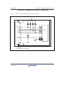
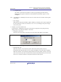
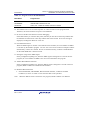
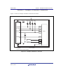
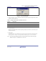
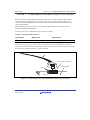
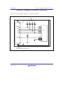
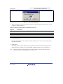
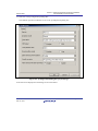
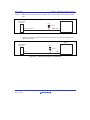
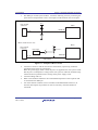
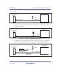
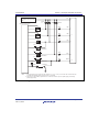
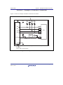
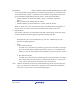
The RES# pin is used by the emulator. Create the following circuit so that reset input
can be accepted from the emulator.
User system
connector
Vcc
MCU
Pin 13
RES# pin
*
Note: For the recommended capacitance of the capacitor that is connected to the RES# pin,
refer to the hardware manual.
Figure 4.4 Example of a Reset Circuit
4.
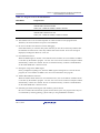
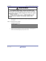
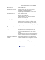
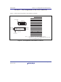
Connect Vss and Vcc with the Vss and Vcc of the MCU, respectively (within the
guaranteed range of the microcomputer).
When the power-supply mode is used, the power is supplied to the user system. Check
that the power consumption or voltage of the user system is within the available range
of E8a and avoid a problem such as closing of the power-supply circuit.
5.
Connect nothing with N.C.
6.
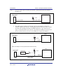
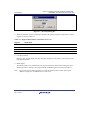
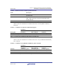
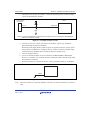
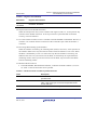
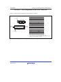
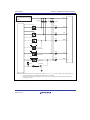
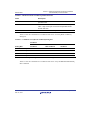
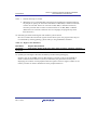
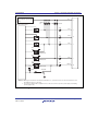
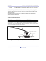
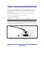
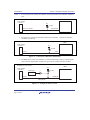
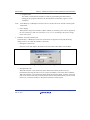
When the emulator is connected to the user system, ground the TEST pin of the MCU.
MCU
TEST
Figure 4.5 Emulator and the TEST Pin
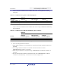
Note: When the emulator is connected, ADTRG#, which is also used as the TEST pin, cannot be
used.
R20UT0637EJ0300 Rev.3.00
Mar 14, 2012
Page 11 of 26