1
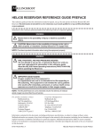
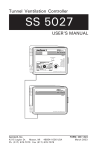
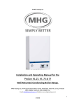
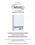
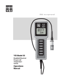
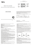
Environment Control
TC4-NVS
USER'S MANUAL
TABLE OF CONTENTS
Page
PRECAUTIONS .............................................................. 3
FEATURES ..................................................................... 4
LOCATION OF THE CONTROLS ................................... 6
FACTORY SETTINGS .................................................... 9
INSTALLATION .............................................................. 10
Mounting Instructions ..................................................... 10
Connections .................................................................. 10
Temperature Probes ..................................................... 11
CONFIGURATIONS ........................................................ 13
CHANGING THE PARAMETER SETTINGS .................. 16
The Meaning of a Flashing Display ................................ 16
Locking the Parameters ................................................ 16
ADJUSTING THE TEMPERATURE ............................... 17
Temperature Units ........................................................ 17
Viewing Temperatures .................................................. 17
Temperature Set Point .................................................. 18
Temperature Curve ....................................................... 19
CURTAINS ...................................................................... 23
Principle of Operation ................................................... 23
Curtain Operating Time Compensation ......................... 25
COOLING AND MIST SETTINGS ................................... 28
Minimum Ventilation Cycle ............................................ 28
Mist Timer ..................................................................... 28
HEATER SETTINGS....................................................... 31
TROUBLESHOOTING GUIDE........................................ 33
ALARM SETTINGS ......................................................... 34
TECHNICAL SPECIFICATIONS .................................... 37
2
TC4-NVS.rev.03
PRECAUTIONS
We strongly recommend installing supplementary natural ventilation as well as a back-up thermostat on stage 2 (refer to
the wiring diagram enclosed with this user's manual to connect
the thermostat) as well as an independent failure alarm system
and a curtain drop or manual winch.
Although fuses at the input and outputs of the controller protect
its circuits in case of an overload or overvoltage, we
recommend installing an additional protection device on the
controller's supply circuit as well as an external relay on stage
2 to prolong the life of the controller.
The room temperature where the controller is located MUST
ALWAYS REMAIN BETWEEN 32°F AND 104°F (0°C TO 40°C).
To avoid exposing the controller to harmful gases or excessive humidity, it is preferable to install it in a corridor.
DO NOT SPRAY WATER ON THE CONTROLLER
FOR CUSTOMER USE
Enter the serial number located on
the side of the controller below for
future reference.
Model number: TC4-NVS
Serial number:
TC4-NVS.rev.03
3
FEATURES
The TC4-NVS is an electronic device used for environmental control in livestock buildings and greenhouses. It allows the user to maintain a specified
target temperature by controlling the operation of ventilation and heating
equipment. One stage of either constant-speed fans, heating units or mist
sprinklers, as well as curtains for natural ventilation, can be connected to
the controller.
The main features of the TC4-NVS are as follows:
THREE-DIGIT DISPLAY
A three-digit display provides a high level of accuracy, allowing the user to
specify a temperature to within one tenth of a degree (in Fahrenheit or Celsius units).
PILOT LIGHTS INDICATING STATE OF OUTPUTS
Pilot lights indicating the state of outputs allow the user to monitor the
operation of the system without having to enter the building.
MINIMUM VENTILATION CYCLE
When ventilation is not required for cooling, the first stage fans can be operated either continously or intermittently to reduce the level of humidity and
supply oxygen to the room.
TEMPERATURE CURVE
The controller can be set to automatically change the temperature set point
over a given period of time in accordance with the user's requirements by
specifying a temperature curve with up to six different points.
FOUR INDEPENDENT TEMPERATURE PROBE INPUTS
Up to four temperature probes can be connected to the controller in order to
obtain a more accurate reading of the average room temperature and a faster
reaction time.
4
TC4-NVS.rev.03
TC4-NVS
HIGH/LOW TEMPERATURE AND POWER FAILURE ALARMS
The controller generates an output signal that will activate any alarm system in case of a rise or fall in temperature beyond a specified limit, a
power failure or a fault in the supply circuit.
ROOM TEMPERATURE COMPENSATION ON CURTAINS
The controller compensates the curtain timer settings proportionally to
room temperature. The lower the temperature, the faster the curtains
close. The higher the temperature, the faster the curtains open.
OVERLOAD AND OVERVOLTAGE PROTECTION
Fuses are installed at the input and outputs of the controller to protect its
circuitry in the case of an overload or overvoltage.
COMPUTER CONTROL
The controller can be connected to a computer, thus making it possible
to centralize the management of information and diversify control strategies.
ADAPTS TO ALL TYPES OF AIR INLET POWER UNITS
TC4-NVS.rev.03
5
6
TC4-NVS.rev.03
LOCKED
ALARM
DEF. PROBE
T CURVE
STAGE 2
CLOS ING
NATURAL
VENTILATIO N
CON TR OLLER
OPENING
LOCATION OF THE CONTROLS
TC4-NVS
1
Three-Digit Display
Displays temperatures and other parameters shown on
the Adjustment Knob.
2
Curtain Opening Pilot Light
Turns on when the curtains open.
3
Curtain Closing Pilot Light
Turns on when the curtains close.
4
Stage 2 Pilot Light
Turns on when Stage 2 fans, heaters or mist units are on.
5
Temperature Curve Pilot Light
Turns on when the temperature curve is activated.
6
Defective Probe Pilot Light
Turns on when a defective probe is detected.
7
Alarm Pilot Light
Turns on when the alarm is activated.
8
Locked Parameter Pilot Light
Turns on when the parameters are locked.
9
Push-Button for Other Functions
Used to access other functions such as specifying the
points of a temperature curve.
10
Parameter Selection Knob
Used to select a parameter.
11
Adjustment Knob
Used to adjust the value of a selected parameter.
TC4-NVS.rev.03
7
TC4-NVS
12
Internal Switches
The internal switches are located on the inside of the front cover and
are defined as follows:
#
1
OFF
ON
UNLOC KED PARAMETERS LOC KED PARAMETERS
2
FAHRENHEIT D EGREES
C ELSIUS D EGREES
3
PROBE 2 D ISABLED
PROBE 2 ENABLED
4
PROBE 3 D ISABLED
PROBE 3 ENABLED
5
PROBE 4 D ISABLED
PROBE 4 ENABLED
6
STAGE 2 C OOLING
STAGE 2 HEATING
7
NORMAL MOD E
PROGRESSIVE MOD E
8
STAGE 2 VENT.
STAGE 2 MIST
NOTE : When the controller is shipped from the factory, all the switches
are set to OFF.
8
TC4-NVS.rev.03
FACTORY SETTINGS
PAR AME T E R
Temperature Set Poi nt
Temperature C urvea
Ti me Openi ng
FAC TORY
SETTIN GS
75
o
F (23.9 oC )
OFF
R AN GE OF VALU ES
-40 to 99.9 oF
(-40 to 37.7 oC )
days < 100
20 seconds
1 to 900 seconds
Ti me C losi ng
20 seconds
Ti me Off
60 seconds
0 to 900 seconds
D i fferenti al
3 oF (1.7 oC )
0.5 to 20 oF
(0.3 to 11.1 oC )
Hi gh offset
12.0oF (6.7oC )
0.5 to 40.0 oF
(0.3 to 22.0 oC )
Low offset
10.0oF (5.6oC )
0.5 to 40.0 oF
(0.3 to 22.0 oC )
Offset
2.0 oF (1.1 oC )
-9.9 to 20 oF
(-5.5 to 11.1 oC )
C urtai ns
Alarm
Ti me On
Stage 2
C ooli ng or
Ti me Off
Heati ng
D i fferenti al
15 seconds
30 seconds
2.0 oF (1.1 oC )
0 to 900 seconds
1 to 60 mi nutes (mi st
only)
0.5 to 20 oF
(0.3 to 11.1 oC )
NOTES :
i) These initial parameter settings will not be retained in the controller's
memory. Each new setting will replace the preceeding one.
ii) If the power supply is cut off, the last parameter settings will be retained in memory until the power is restored.
(a) The range of values for curve temperatures is 35°F to 99.9°F (1.7°C to 37.7°C).
TC4-NVS.rev.03
9
INSTALLATION
MOUNTING INSTRUCTIONS
Remove the four screws on the front cover and lift the cover. Mount the
enclosure on the wall using three screws. Be sure the electrical knockouts
are at the bottom of the enclosure in order to prevent water from entering the
controller. Insert the screws in the mounting holes provided in three corners
of the enclosure and tighten. Fasten the three black caps provided with the
controller onto the three mounting holes.
CONNECTIONS
To connect the controller, refer to the wiring diagram enclosed with this user's
manual.
ð Set the voltage switch to the appropriate voltage.
ð Use the electrical knockouts provided at the bottom of the enclosure. Do not make additional
holes in the enclosure, particularly
on the side of the enclosure when
using a computer communications
module.
ð If Stages 2 is used for heating, it may be
necessary to install a transformer in
order to supply the appropriate voltage to the heating unit.
CONCERNING THE ALARM CONNECTION: There are two types of alarms
in the industry. One type activates when current is cut off at its input, whereas
the other activates when current is supplied at its input. For an alarm of the
first type, use the NO terminal as shown in the wiring diagram. For an alarm
of the second type, use the NC terminal.
10
TC4-NVS.rev.03
TC4-NVS
!
WARNING
ALL WIRING MUST BE DONE BY AN AUTHORIZED ELECTRICIAN
AND MUST COMPLY WITH APPLICABLE CODES, LAWS AND
REGULATIONS. BE SURE POWER IS OFF BEFORE DOING ANY
WIRING TO AVOID ELECTRICAL SHOCKS AND EQUIPMENT DAMAGE.
TEMPERATURE PROBES
1
Connecting the Probes
The controller is supplied with one temperature probe connected to terminal
# 1. Three additional indoor probes can be connected to improve accuracy
and reaction times.
ð
Use terminals # 2, 3 and 4 to connect additional indoor probes, as
shown on the wiring diagram enclosed.
Switches are used to activate or deactivate the additional probes connected
to the controller. Activate each additional probe by setting the appropriate
switch to ON:
ð
ð
ð
Switch # 3 activates the probe connected to terminal # 2.
Switch # 4 activates the probe connected to terminal # 3.
Switch # 5 activates the probe connected to terminal # 4.
CAUTION: Probes operate at low voltage and are insulated from the
supply. Be sure that probe cables remain insulated from all high voltage
sources. In particular, do not route the probe cables through the same
electrical knockout as other cables. Do not connect the shield from the probe
cable to a terminal or a ground.
TC4-NVS.rev.03
11
TC4-NVS
2
Extending the Probes
Each probe can be extended up to 500 feet (150 m):
ð Use a shielded cable of outside diameter between 0.245 and 0.260
in (6.22 and 6.60 mm) to ensure the cable entry is liquid tight
(cable dimensions should not be under 18 AWG). Do not ground
the shielding.
ð It is preferable to solder the cable joint to ensure a proper contact
between the two cables.
CAUTION: Do not run probe cables next to other power cables. When
crossing over other cables, cross at 90o.
3
Detecting Faulty Probes
If a faulty probe is detected, the Defective Probe pilot light turns on. The
room temperature shown on the display is then the average temperature
measured by the probes in working condition. The controller will operate
according to this temperature.
To identify the faulty probe:
ð Set the selection knob to AMBIENT. The room temperature is displayed.
ð Press the push-button. If the probe connected to terminal # 1 is not
faulty, "Pr 1" is displayed, alternating with the temperature measured
by the probe. Otherwise, "Pr 1" alternates with "P".
ð Keep pressing the push-button to view the status of the other probes.
NOTE: If all the probes are defective, the controller operates the cooling
stages in minimum ventilation mode.
12
TC4-NVS.rev.03
CONFIGURATIONS
STAGE 2 — HEATING
ON12345
12345
12345
12345
12345
12345
12345
12345
12345
12345
12345
12345
12345
12345
12345
12345
12345
12345
12345
12345
12345
12345
12345
12345
12345
12345
12345
12345
12345
12345
12345
12345
12345
12345
12345
1
2
3
4
5
6
12345
12345
12345
12345
12345
12345
12345
12345
12345
12345
12345
12345
12345
12345
7
8
Operation
Heater
Heater units
turn on
Heater units
turn off
Diff.
Offset
Temperature
Set Point
Temperature rises: When the temperature rises to Set Point - Offset, the
heater units turn off. At Set Point + Diff. 1, the curtains begin to open
intermittently according to the curtain timer settings.
Temperature falls: When the temperature falls to Set Point - Diff. 1, the
curtains begin to close intermittently according to the curtain timer settings. At Set Point - Offset - Diff., the heater units turn on.
Note: Heating units do not operate with the timer.
TC4-NVS.rev.03
13
TC4-NVS
STAGE 2 — VENTILATION COOLING
12345
ON12345
12345
12345
12345
12345
12345
12345
12345
12345
12345
12345
12345
12345
12345
12345
12345
12345
12345
12345
12345
12345
12345
12345
12345
12345
12345
12345
12345
12345
12345
12345
12345
12345
12345
1
2
3
4
5
12345
12345
12345
12345
12345
12345
12345
6
7
8
Ventilation
Stage 2
Stage 2 fans
stop running
Offset
Stage 2 fans
start running
Diff.
Temperature
Set Point
Temperature rises: When the temperature rises to Set Point + Diff. 1, the
curtains begin to open intermittently according to the curtain timer settings.
At Set Point + Offset + Diff., the Stage 2 fans start to run.
Temperature falls: When the temperature falls Set Point + Offset, the
Stage 2 fans stop running. At Set Point - Diff. 1, the curtains begin to close
intermittently according to the curtain timer settings.
14
TC4-NVS.rev.03
TC4-NVS
STAGE 2 — MIST COOLING
12345
ON12345
12345
12345
12345
12345
12345
12345
12345
12345
12345
12345
12345
12345
12345
12345
12345
12345
12345
12345
12345
12345
12345
12345
12345
12345
12345
12345
12345
12345
12345
12345
12345
12345
12345
1
2
3
4
5
12345
12345
12345
12345
12345
12345
12345
6
7
8
Operation
Stage 2
Stage 2 mist
starts running
Stage 2 mist
stops running
Offset
Diff.
Temperature
Set Point
Temperature rises: When the temperature rises to Set Point + Diff. 1, the
curtains begin to open intermittently according to the curtain timer settings.
At Set Point + Offset + Diff., the Stage 2 mist units start to run according to
the timer 2 settings.
Temperature falls: When the temperature falls to Set Point + Offset, the
Stage 2 mist units stop running. At Set Point - Diff. 1, the curtains begin to
close intermittently according to the curtain timer settings.
NOTE: The mist timer operates in minutes (1 to 60 minutes).
TC4-NVS.rev.03
15
CHANGING THE PARAMETER SETTINGS
THE MEANING OF A FLASHING DISPLAY
The display will flash in certain cases and not in others.
The flashing indicates that the
value shown can be adjusted.
A value that is not flashing
cannot be adjusted.
LOCKING THE PARAMETER SETTINGS
The parameter settings can be locked to prevent accidentally modifying
them. When the settings are locked, only the temperature set point can be
modified (as long as the temperature curve is deactivated).
To lock the parameter settings:
ð Set internal switch # 1 to ON. The Locked Parameter Pilot Light
turns on.
To unlock the parameter settings:
ð Set internal switch # 1 to OFF. The Locked Parameter Pilot Light
turns off.
16
TC4-NVS.rev.03
ADJUSTING THE TEMPERATURE
TEMPERATURE UNITS
Temperatures can be displayed in either Celsius or Fahrenheit units
ð Set internal switch # 2 to the desired position:
ON
• ON to display temperatures in Celsius units.
• OFF to display temperatures in Fahrenheit units.
2
VIEWING TEMPERATURES
The readout can display values from -40.0oF to 120.0oF (-40.0oC to 48.9oC).
When the temperature drops below -9.9 degrees, the negative sign is
displayed separately, alternating with the numerical value.
1
Viewing the Room Temperature
The room temperature is the average value of all temperatures measured by
activated probes in proper operating condition.
ð Set the selection knob to AMBIENT. The room temperature is displayed.
2
Viewing Probe Temperatures
The controller can display probe temperatures individually. Probes can also
be turned on or off to control the temperature in different parts of the building
by using internal switches # 3, 4 and 5.
ð Set the selection knob to AMBIENT. The room temperature is displayed.
ð Press the push-button. "Pr 1" is displayed, alternating with the
temperature measured by the probe connected to terminal # 1 (supplied with the controller).
TC4-NVS.rev.03
17
TC4-NVS
ð Press the push-button once again to display the temperature, etc.
3
Viewing Minimum / Maximum Temperatures
The minimum and maximum temperatures are the lowest and highest temperature values recorded since the last reset. Temperatures values are
averaged over all active probes.
ð Set the selection knob to AMBIENT. The room temperature is displayed.
ð Turn the adjustment knob clockwise by one notch. The minimum
temperature flashes on the display.
ð Turn the adjustment knob counterclockwise one notch. The maximum temperature flashes on the display.
NOTE: If you let the display flash for more than 10 seconds, the controller resets the minimum and maximum temperatures currently in memory
(the display stops flashing to indicate that the reset has been done).
TEMPERATURE SET POINT
The temperature set point is the target room temperature. It can be adjusted between -40.0°F and 99.9°F (-40.0°C and 37.7°C).
1
Adjusting the Temperature Set Point
ð Set the selection knob to SET POINT / TEMP. CURVE.The current
set point flashes on the display.
ð Use the adjustment knob to adjust the set point to the desired value.
18
TC4-NVS.rev.03
TC4-NVS
NOTE: The temperature set point can be adjusted only if the temperature
curve is deactivated (see following section).
TEMPERATURE CURVE
The user can define a temperature curve to adjust the set point automatically
over a given time period.
A curve is defined using six points. Each point specifies a day number and
a set point for that day. Once the points of the curve are defined, the curve
must be activated. The controller will change the temperature set point every
hour in a linear fashion between consecutive points of the curve. When the
last point of the curve is reached, the temperature set point for that day is
maintained until the curve is reactivated.
NOTES :
i) All six points of the curve must be specified. If six points are not needed,
repeat the last temperature value for each unnecessary point.
ii) Certain restrictions apply to reduce the risk of errors:
− The highest possible day number is 99.
− Decreasing day numbers are not allowed.
− Increasing temperatures are not allowed.
− The temperature variation cannot exceed 3°F (1.6°C) per day.
○
○
○
○
○
○
○
○
○
○
○
○
○
○
d35
d50
d70
○
○
○
○
○
○
○
○
○
○
○
d25
○
○
○
○
○
○
○
d4
○
○
○
○
○
○
○
○
○
T o1
T o2
T o3
T o4
T o5
T o6
○
Temperature
d80 Days
TC4-NVS.rev.03
19
TC4-NVS
1
Specifying the Temperature Curve
ð Set the selection knob to SET POINT /TEMP. CURVE. The current
temperature set point flashes on the display.
ð Press the push-button. The word OFF is displayed indicating that the
termperature curve is deactivated. If this is not the case, see below
to deactivate the curve.
Repeat the following steps for each of the six points:
ð Press the push-button once again. The letter "d" followed by a day
number flashes on the display.
ð Using the adjustment knob, set the day number to the desired value.
ð Press the push-button once again. The current temperature set point
flashes on the display.
ð Using the adjustment knob, adjust the set point to the desired value.
Once the six points of the curve have been specified, activate the curve as
explained below.
NOTE: Make sure the temperature curve is deactivated before specifying
new points (see below).
2
Activating the Temperature Curve
If you have just finished specifying the points on the curve:
ð Press the push-button once again. The word OFF flashes on the
display.
20
TC4-NVS.rev.03
TC4-NVS
ð Turn the adjustment knob clockwise one notch and leave in this
position for at least 10 seconds. The word ON flashes on the display and after 10 seconds, the Temperature Curve Pilot Light turns
on indicating that the temperature curve is now activated.
ð Set the selection knob to AMBIENT.
If you have previously defined the points on the curve:
ð Set the selection knob to SET POINT / TEMP. CURVE. The current
value of the temperature set point flashes on the display.
ð Press the push-button. The word OFF flashes on the display.
ð Press the push-button to display the points of the curve currently
defined until the word OFF appears (thirteen clicks).
ð Turn the adjustment knob clockwise one notch and leave in this
position for at least 10 seconds. The word ON flashes on the display and after 10 seconds, the Temperature Curve Pilot Light turns
on indicating that the temperature curve is now activated.
ð Set the selection knob to ROOM TEMPERATURE.
3
Viewing Current Set Point and Day Number
When the temperature curve is activated, the current temperature set
point and day number can be viewed at any time. The current day
number can also be adjusted in order to move forward or backward on
the temperature curve.
ð Set the selection knob to SET POINT / TEMP. CURVE. The current
temperature set point flashes on the display.
ð Press the push-button. The current day number is displayed.
ð Use the adjustment knob to set the day number to the desired
value.
TC4-NVS.rev.03
21
TC4-NVS
4
Deactivating the Temperature Curve
ð Set the selection knob to SET POINT /TEMP. CURVE. The current
temperature set point flashes on the display.
ð Press the push-button to display the points of the curve actually
defined until the word ON appears (fourteen clicks).
ð Turn the adjustment knob counterclockwise one notch and leave in
this position for at least 10 seconds. The word OFF flashes on the
display and after 10 seconds, the Temperature Curve Pilot Light turns
off indicating that the temperature curve is now deactivated.
ð Set the selection knob to AMBIENT.
22
TC4-NVS.rev.03
CURTAINS
PRINCIPLE OF OPERATION
Curtains open
in timer mode
Curtains close
in timer mode
0.3oF
0.3oF
Curtains
OFF
70oF Set Point
= 75oF
80oF
Room
Temperature
In the example above, the differential is set to 5oF. When the temperature
rises to 80oF (set point + differential), the curtains begin to open and continue to do so until fully open if the temperature remains above this point. If
the temperature falls to 79.7oF, the curtains stop opening. The curtains
open intermittently according to the time opening and time off settings:
TIMEOPENING
OPEN
STOP OPENING
TIME OFF
o
When the temperature falls to 70 F (set point - differential), the curtains
begin to close and continue to do so until fully closed if the temperature
remains below this point. If the temperature rises to 70.3oF, the curtains
stop closing. The curtains close intermittently according to the time
closing and time off settings:
TIME CLOSING
CLOSE
STOP CLOSING
TIME OFF
TC4-NVS.rev.03
23
TC4-NVS
1
Manual Operation of the Curtains
ð Set the selection knob to MANUAL OPERATION. The display flashes
"OFF" and the curtains stop functioning after five seconds.
ð Press the push-button. The display flashes "OPE" and the curtains
start opening after five seconds.
ð Press the push-button. The display flashes "CLO" and the curtains
start closing after five seconds.
ð Keep pressing the push-button to stop, open or close the curtains in
that order.
2
Adjusting the Curtain Differential
The differential is the temperature difference from the set point at which the
curtains start to open or close (see Figure 1 above). The differential can be
adjusted between 0.5° and 20°F (0.3°C and 11.1°C)
ð Set the selection knob to CURTAINS - DIFFERENTIAL. The current
curtain differential flashes on the display.
ð Use the adjustment knob to set the differential to the desired value.
3
Adjusting the Curtain Timer
ð Set the selection knob to CURTAINS - OPENING TIME. The current
curtain time opening flashes on the display.
ð Use the adjustment knob to set the time opening to the desired
value.
ð Set the selection knob to CURTAINS - CLOSING TIME. The current
curtain time closing flashes on the display.
24
TC4-NVS.rev.03
TC4-NVS
ð Use the adjustment knob to set the time closing to the desired value.
ð Set the selection knob to CURTAINS - TIME OFF. The current curtain time off flashes on the display.
ð Use the adjustment knob to set the off time to the desired value.
The time opening and time closing can take values from 1 to 900 seconds. The
time off can take values from 0 to 900 seconds.
CURTAIN OPERATING TIME COMPENSATION
1
Normal Mode (Without Compensation)
The curtains open and close intermittently according to the specified time
opening , time closing and time off, as described on the preceding pages.
There is no room temperature compensation. To operate the controller in
this mode, set internal switch # 7 to OFF.
2
Progressive Mode (With Compensation)
The controller can use the current room temperature to adjust the time
opening and time closing of the curtains. To use this feature, set internal
switch # 7 to ON.
Temperature Rises:
When the room temperature rises by a certain number of degrees above
"temperature set point + differential" , the controller increases the Time
Opening value and reduces the Time Off so that the total cycle time remains constant.
The higher the room temperature, the faster the curtains open. When
Time Off is below 10 seconds, the curtains begin to open continuously.
TC4-NVS.rev.03
25
TC4-NVS
EXAMPLE 1
Set Point = 75 oF
Temperature = 78.3 oF
Differential = 3 oF
Compensation = 1
TIME
OPENING
ON
OFF
CYCLE
According to Table 1 below, the temperature difference of 0.3 degrees gives
a compensation factor of one. Therefore, the Time Opening value maintains its current value.
In the first example above, the temperature has risen to:
Set Point:
Differential:
+
+
=
75 oF
3 oF
0.3 oF
78.3 oF
Table 1. Compensation Factors
Temperature Difference from
Compensation
Set Point + Diff. (for time opening)
Factor
Set Point - Diff. (for time closing)
0 to 0.9 oF (0 to 0.5 oC)
1.0 to 1.9 oF (0.6 to 1.1 oC)
2.0 to 2.9 oF (1.1 to 1.6 oC)
1
2
4
etc...
26
TC4-NVS.rev.03
TC4-NVS
EXAMPLE 2
Set Point = 75 oF
Temperature = 79.8 oF
Differential = 3 oF
Compensation = 2
ON
TIME
OPENING
OFF
CYCLE
In the second example above, the temperature has risen to:
Set Point:
Differential:
+
+
=
75 oF
3 oF
1.8 oF
79.8 oF
According to Table 1 above, the temperature difference of 1.8 degrees gives
a compensation factor of two. Therefore, the Time Opening value is doubled.
Temperature Falls:
When the room temperature falls by a certain number of degrees below
"temperature set point - differential", the controller increases the Time Closing
value and reduces the Time Off value so that the total cycle time remains
unchanged.
The lower the room temperature, the faster the curtains close. When the
Time Off value is below 10 seconds, the curtains begin to close continuously. The controller uses the compensation factors given in Table 1.
TC4-NVS.rev.03
27
COOLING AND MIST SETTINGS
MINIMUM VENTILATION CYCLE
The controller uses a timer cycle to operate the fans when they are not
needed for cooling. This helps reduce humidity levels and supplies oxygen
to the room. To take advantage of this feature, the time on settings of the
cooling fan stages needed for minimum ventilation must be set to a non-zero
value.
TIME ON
ON
OFF
TIME OFF
To run the units intermittently: set TIME ON to the desired on time and
TIME OFF to the desired off time.
To run the units continuously: set TIME OFF to zero and TIME ON to any
value other than zero.
To stop the units: set TIME ON to zero and TIME OFF to any value (equal
to or other than zero).
MIST TIMER
The mist units operate according to a separate timer which functions in the
same way as the minimum ventilation timer described above. When the
temperature is such that stage 2 (defined as a mist stage) is in operation,
the mist units run through the cycle settings defined for stage 2.
28
TC4-NVS.rev.03
TC4-NVS
1
Adjusting the Minimum Ventilation or Mist Timer
ð Set the selection knob to STAGE 2 - TIMER. The current Time On
is displayed, alternating with the word "On".
ð Use the adjustment knob to set the Time On to the desired value.
ð Press the push-button. The current Time Off is displayed, alternating with the word "Off".
ð Use the adjustment knob to set the Time Off to the desired value.
The time on and time off parameters can take values from 0 to 900 seconds,
in increments of 15 seconds. In the case of the mist timer, values range
from 1 to 60 minutes, in increments of 1 minute.
2
Adjusting the Cooling or Mist Differential
The differential for Stage 2 is the temperature difference between the moment
the fans or mist units start to run for that stage and the moment they return
to a stop (see the diagram in the Configurations Section). Differentials can be
adjusted between 0.5°F and 20.0°F (0.3°C and 11.1°C).
ð Set the selection knob to STAGE 2 - DIFFERENTIAL. The current
differential flashes on the display.
ð Use the adjustment knob to set the differential to the desired value.
TC4-NVS.rev.03
29
TC4-NVS
3
Adjusting the Cooling or Mist Offset
The offset for Stage 2 is the temperature interval from the set point at which
the fans or mist units turn off (see the diagram in the Configurations Section).
The offset can be adjusted between 0.5°F and 20.0°F (0.3°C and 11.1°C).
ð Set the selection knob to STAGE 2 - OFFSET. The current offset
flashes on the display.
ð Use the adjustment knob to set the offset to the desired value.
30
TC4-NVS.rev.03
HEATER SETTINGS
1
Adjusting the Heating Differential
The heating differential is the temperature difference between the moment the
heating units turn on and the moment they turn off (See the operating
diagrams in the Configuration Section.
ð Set selection knob to STAGE 2 - DIFFERENTIAL. The current differential flashes on the display.
ð Use the adjustment knob to set the differential to the desired value.
The differential can be adjusted between 0.5°F and 20.0°F (0.3°C and 11.1°C).
2
Adjusting the Heater Offset
The heater offset can provide substantial energy savings if correctly adjusted
according to the outside temperature. It is the number of degrees below the
set point at which the Stage 2 heating units turn off (see diagram in the
Configuration section).
ð Set selection knob to STAGE 2 - OFFSET. The offset value flashes
on the display.
ð Use the adjustment knob to set the offset to the desired value.
The heater offset can be adjusted between 0 and 20.0 °F (0 and 11.1 °C) if
the negative heater offset is deactivated; it can be adjusted between -9.9
and 20.0 °F (-5.5 and 11.1 °C) if the negative heater offset is activated.
TC4-NVS.rev.03
31
TC4-NVS
3
Enabling / Disabling Negative Heater Offset
Normally, the heater offset is set to a positive value. It may also be useful to
set it to a negative value to allow the heating units to operate when the room
temperature is above the set point. In that case, the negative heater offset
must be activated.
ð Set the selection knob to STAGE 2 — OFFSET. The current heater
offset flashes on the display.
ð Press the push-button. The word ON or OFF flashes on the display.
Turn the adjustment knob to set the negative offset option to the desired
state. After 10 seconds, the display returns to the heater offset value.
When the negative offset option is enabled, the offset ranges from -9.9°F to
20.0°F (-5.5°C to 11.1°C).
32
TC4-NVS.rev.03
ALARM SETTINGS
The controller activates the alarm when the temperature reaches a high or low
extreme or in case of a power failure or faulty circuit
1
Adjusting the High Offset
The alarm high offset is the number of degrees above the set point at which
an alarm is set off.
ð Set the selection knob to ALARM - HIGH OFFSET. The current
high offset flashes on the display.
ð Using the adjustment knob, adjust the high offset to the desired value.
The high offset can be adjusted between 0.5oF and 40.0oF (0.3oC and 22.0oC)
1
Adjusting the Low Offset
The alarm low offset is the number of degrees below the set point at which
an alarm is set off.
ð Set the selection knob to ALARM - LOW OFFSET. The current low
offset appears flashing on the display.
ð Using the adjustment knob, adjust the low offset to the desired value.
The low offset can be adjusted between 0.5oF and 40.0oF (0.3oC and 22.0oC)
TC4-NVS.rev.03
33
TROUBLESHOOTING GUIDE
PROBLEM
CAUSE
The display
doesn't work.
The circuit breaker on
the service panel is off
or tripped.
Reset the circuit breaker.
The wiring is incorrect.
Fix the wiring.
The F6 input fuse is
open.
Replace the fuse.
The voltage selector
switch is in the wrong
position.
Set the switch to the correct
position.
The display board
interconnect cable is
unplugged from the
power supply board.
Plug the cable.
The display
shows the
letter "P" and
the defective
probe pilot
light is on.
All the probes connected to the controller
are defective.
Replace the probes.
The Defective
Probe Pilot
Light is on.
One or more probes
are defective.
Follow the procedure described
in DEFECTIVE PROBES to
identify and replace the defective probe.
34
TC4-NVS.rev.03
SOLUTION
TC4-NVS
PROBLEM
CAUSE
The display
shows
sudden
variations in
room temperature.
A variation in resistance is induced on a
probe.
Make sure the probes are dry
and move them away from
drafts and sources of radiant
heating.
There is electrical
noise near an extended probe cable.
Isolate the probe cables from
all high voltage sources. Do
not run probe cables through
the same electrical knockout.
Do not run probe cables next to
other power cables. When
crossing other power cables,
cross at 90o.
The curtains
do not work.
The F1 fuse on the
curtain output is
blown.
Replace the fuse.
The curtains
operate in
manual mode
but not in
automatic
mode.
The curtain operating
parameters are set
incorrectly.
Correct the parameter settings.
SOLUTION
TC4-NVS.rev.03
35
TC4-NVS
PROBLEM
The fans,
heating or
mist units
connected to
one of the
stages are
not operating.
36
CAUSE
SOLUTION
The stage's fuse is
open.
Replace the fuse.
The display board
interconnect cable is
not plugged into the
power supply board
properly.
Make sure the cable is firmly
plugged in with the tabs in place.
The wiring is incorrect.
Correct the wiring. In particular,
make sure two different lines
are connected to each motor:
line L1 modulated by the
controller should be combined
with another line (N for 115V or L2
for 230V) to activate the motor or
heating unit. Also, make sure the
stage's COMMON is supplied by
line L1.
The fan motor,
heating or mist unit is
defective.
Verify if the motor, heating or
mist unit is defective by connecting it to an alternate power
supply. Replace If it still is not
operating.
The controller is
defective.
Listen to see if there is a clicking
sound when the stage's pilot
light turns on. If there is no
clicking sound, contact your
distributor to repair the controller.
TC4-NVS.rev.03
TECHNICAL SPECIFICATIONS
Supply: - 115/230 VAC, (-18%,+8%), 50/60 Hz, overload and overvoltage
protection fuse F6-1A fast blow.
- 12 VDC for AC back-up supply, can activate Stage 2 and alarm
if supplied with DC back-up voltage.
Curtain: OPEN-CLOSE output, 115/230 VAC, 50/60 Hz, 30 VDC, 5A winch
output, fuse F1-5A slow blow.
Stage 2: ON-OFF output, 115/230 VAC, 50/60 Hz, 30 VDC, 6A FAN, 10A
RES, fuse F3-10A slow blow.
Alarm: ON-OFF output, 115/230 VAC, 50/60 Hz, 30 VDC, 3A, fuse F4-3A
slow blow.
Probes: Low voltage ( < 5V), isolated from the supply. Operating range:
-40.0° to 120.0°F (-40.0° to 48.9°C). Accuracy: 1.8oF (1oC) between 41o and
95oF (5o and 35oC).
Enclosure: ABS, moisture and dust-tight.
The room temperature where the controller is located MUST
ALWAYS REMAIN BETWEEN 32o AND 104oF (0o AND 40oC).
TC4-NVS.rev.03
37