1
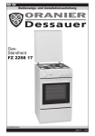
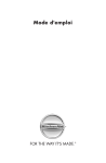
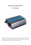
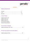
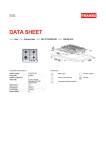
1.INTRODUCTION
Thank you for purchasing a new Gas Hob.
Semirapid
gas burner
1750W
Semirapid
gas burner
1750W
Rapid
gas burner
3000W
Auxiliary
gas burner
1000W
Semirapid
gas burner
1750W
Triple flame
gas burner 3800W
Semirapid
gas burner
1750W
Auxiliary
gas burner
1000W
GHG602BL
BUILT-IN GAS HOB
Semirapid
gas burner
1750W
Semirapid
gas burner
1750W
INSTALLATION AND USER INSTRUCTIONS
GHG602BL
GHG601BL
GHG701BL
GHG703BL
GHG901BL
SSG601SS
SSG701SS
Triple flame gas burner 3800W
GHG601BL
SSG601SS
Rapid
gas burner
3000W
Semirapid
gas burner
1750W
Auxiliary
gas burner
1000W
Semirapid
gas burner
1750W
Triple flame gas burner 3800W
Rapid
gas burner
3000W
Auxiliary
gas burner
1000W
GHG703BL
GHG701BL
SSG701SS
Triple flame gas burner 3800W
Semirapid
gas burner
1750W
Rapid
gas burner
3000W
Semirapid
gas burner
1750W
Auxiliary
gas burner
1000W
GHG901BL
Even if you have used a gas hob before, it is important that you read these instructions thoroughly
before starting to cook, paying particular attention to the installation and safety instructions. If you
have any problems with installing, operating, or cooking with your hob, please check through these
instructions thoroughly to make sure that you have not missed anything.
WARNING! For your own safety , make sure that these instructions on Installation, use and
maintenance are followed.
We advise you to keep these instructions in a safe place for future reference.
If you sell or transfer ownership of this product, please pass on these instructions to the new owner.
2. YOUR HOB
Applicable For gas
Type
GHG602BL
GHG601BL
GHG701BL
GHG703BL
GHG901BL
Note: Do not use the hob until you have read the instruction manual
SSG601SS
SSG701SS
Triple flame Rapid
Semirapid Auxiliary
gas burner gas burner gas burner gas burner
Material
/
3000W
1750W
1000W
Glass
3800W
3000W
3000W
1750W
1750W
1000W
1000W
Glass
3000W
3000W
/
3000W
1750W
1750W
1750W
1750W
1000W
1000W
1000W
1000W
3800W
3800W
3800W
3800W
3800W
Cod: 0070301123
Flame
failure
device
Power
Supply
Size
(mm)
Yes
Yes
220-240V ~60/50Hz
220-240V ~60/50Hz
500x 580x90
510x 580x90
477x557
Glass
Yes
220-240V ~60/50Hz
510x 700x90
477x557
Glass
Glass
Glass
Glass
Yes
Yes
Yes
Yes
220-240V ~60/50Hz
220-240V ~60/50Hz
510x 700x90
510x 860x90
500x 580x80
500x 680x80
477x557
477x837
220-240V ~60/50Hz
220-240V ~60/50Hz
4.SAFETY INSTRUCTIONS
Ensure that these notes and that the whole of this instruction book are thoroughly read and understood
before installation or operation of the hob.
The instructions are provided in the interest of your safety.
GAS SAFETY (INSTALLA TION & USE) REGULATIONS
1.It is the law that all gas appliances are installed by competent persons in accordance with
current edition of the above regulations. It is In your interest and that of safety to ensure compliance
with the law.
2.Repairs or servicing of this product must only be carried out by an authorised agent service agent
service agent using only approved parts.
3.No attempt must be made to modify this appliance.
4.Cooking appliances become very hot in use, therefore ensure children and pets are kept away.
The use of oven gloves is recommended when during use,
5.Do not allow children to operate or play with any part of the appliance.
6.Do not use unstable pans and position handle away from the edge of the hob.The use of a suitable hob .
7.In the interests of safety and hygiene, ensure the hob is kept clean as a build up of grease could cause
8.This appliance is designed for domestic cooking only, commercial catering may invalidate the warranty.
9.Do not cover the hob or place combustible materials on or near the surface even when the hob is not in use.
10.Do not fill deep fat frying pans more than one third full of oil. Do not leave unattended.
11.Before cleaning the hob, switch off at the mains.
12.When finished cooking, switch all controls off and allow to cool.
13.If you sell or transfer ownership of this product, please pass on these instructions to the new owner.
14.This appliance is not intended for use by persons (including children) with reduced physical,
sensory or mental capabilities, or lack of experience and knowledge, unless they have been given
supervision or instruction concerning use of the appliance by a person responsible for their safety.
15.Children should be supervised to ensure that they do not play with the appliance.
16.If the supply cord is damaged, it must be replaced by the manufacturer or its service agent or
a similarly qualified person in order to avoid a hazard.
17.Do not immerse appliance or power cord into water or any other liquids.
18.Please pull the pin out when you do cleaning and maintenance. When the appliance is installed,
you can pull out the pin.
5. INSTALLA TION INSTRUCTIONS
TECHNICAL INFORMATION
The Installation, the adjustments, conversions and maintenance listed in this part must only be
carried out by qualified persons.
The safety and automatic adjustment devices of the appliance may only be modified by an authorised
service agent.
The Installation of this gas hob must comply with the standards in force.
This appliance is not connected to a flue for discharge of the combustion products; therefore, it
2
477x557
477x557
477x557
3.CLEANING
VITREOUS ENAMEL
Hotplate, burner caps, pan supports.
Cloth wrung out in hot soapy water. Stubborn stains.can be removed with a cream paste.
approved by the Vitreous Enamel Development Council, liquid cleaner or by rubbing with
fine steel wool soap pads.
NOTE: The pan supports can also be cleaned in the dishwasher.
ALUMINIUM
Hotplate burner bodies.
Similar to paint cleaning above. Use a nylon brush to remove any cleaning materials, water or dirt from the
hotplate burner bodies. After cleaning, wipe dry and refit to the hob ensuring they are correctly seated.
Check parts are reassembled correctly by lighting the burners and allowing to dry out.
PLASTIC
Control knobs.
Wipe with a cloth wrung out in hot soapy water.
STAINLESS STEEL
Cloth wrung out in hot soapy water.
Built-in
(mm)
1
must be connected in compliance with the above mentioned installation rules. Particular attention
must be paid to the instructions given below for ventilation and aeration.
WARNING!
The appliance must not be connected to a combustion products evacuation device. It shall be installed
and connected in accordance with current installation regulations. Particular attention shall be given to
the relevant instructions regarding ventilation.
LOCATION
The cooker may be located in a kitchen, kitchen/diner or a bed-sitting room, but not in a room containing
a bath or shower. The hob must not be installed in a bed-sitting room of less than 20m . 3
LPG models shall not be installed in a room or internal space below ground level, e.g. in a basement.
PROVISION FOR VENTILATIO
The room containing the cooker should have an air supply in accordance with BS 5440: Part 2.
The room must have an opening window or equivalent; some rooms may also require a permanent
vent. If the room has a volume between 5 and 103m , it will require an air vent of 50cm2 effective
area unless it has a door which opens directly to If the room has a volume of less than 5 m3,
it will require an air vent of 100 cm2 effective area (fig.1). If there are other fuel burning appliances in
the same room, BS 5440: Part 2 should be consulted to determine air yent requirements.
NOTE: The use of a gas cooking appliance results in the production of heat and moisture in the room
in which it is installed. Always ensure that the kitchen is well ventilated; keep natural ventilation holes
open or install a mechanical ventilation device (fig 2).
In particular, when using the grill or more than one hotplate burner, open a window if a mechanical
ventilation device is not operating (fig. 3).
(*)Air inlet minimum section:100c㎡
Fig 1
Fig 2
Fig 3
UNPACKING THE APPLIANCE
Remove all packaging before use and check to make sure that the appliance is In perfect condition.
If you have any doubts do not use the appliance and call your supplier.
Some parts on the appliance are protected by a plastic film. This protective film must be removed
before the appliance is used. We recommend carefully slitting the plastic film along the edges with
a sharp knife or pin.
The packaging materials should carefully discarded and not left within easy reach of children as
they are a potential safety hazard.
INSTALLING AND FIXING THE HOB
Your hob can be fitted to any worktop with a thickness of 40 to 50 mm,
accordance with No overhanging surface or cooker hood should be closer to the hotplate than 750 mm.
Fix in position in fig, 4. If fitting a 600 mm bridging unit above the 700 mm hob unit, the sides of
adjacent cabinets may be lower than 760 mm down to 334 mm provided they are resistant to heat and steam.
The hob has a speciaf seal which prevents liquid from entering the cabinet Follow these instructions
in order to correctly apply this seal:
3
Detach the seals from their backing, that the transparent protection still adheres to the seal itself.
Turn over the hob and correctly position seal *E* (fig. 5) under the edge of the hob itself, so that the
outer part of the seal itself perfectly matches the outer edge of the hob. The ends of the strips must
fit together without overlapping. Evenly and securely fix the seal to the hob, pressing it firmly in place.
B
C
557 477
65
GHG901BL
A
D
E
F
G
62 150min 90min 750min
D
C
B
G
A
GHG701BL SSG601SS SSG701SS
F
GHG602BL GHG601BL GHG703BL
GAS CONNECTION
The appliance's gas inlet fitting is a 1/2" male threaded conic gas type in accordance with the
ISO 7-1 standards. Make the connection using rigid pipe.
When making the gas connection, it is important to place the gasket (A)
in between the inlet pipe (C) and the elbow (B), toensure a gas tight seal.
Unit:mm
E
A
E
Fig 4
B
C
837 477
65
D
E
F
G
E
E
62 150min 90min 750min
ELECTRICAL CONNECTION
This appliance must be connected by a competent person, using fixed wiring via a double pole
Fig 5
Installation options
Option:
When fitting a gas hob above a drawer or standard housing unit, suitable precautions must be taken
to prevent contact.
with the casing of the hob, which becomes very hot during operation. The recommended method
for overcoming this problem is to fix a wooden panel within the cabinet at a distance of 15mm below
the underside of the hob (see fig 1). This panel must have adequate ventilation to the rear.
switched fused spur outlet with a fuse rating of 3amps, and with a contact separation of at least
3mm in all poles.
We recommend that the appliance is connected by a qualified electrician who will comply with
I.E.E regulations.
The wires in the mains lead are coloured in accordance with the following code: Green & Yellow = Earth,
Blue = Neutral, Brown = Live.
CONNECTION DIAGRAM
Caution! Voltage of heating elements 220-240V
PE terminal.
Wire must be connected to the
Ventilation slot > 30mm
Recommended
type of
connection
lead
L
For 220-240V earthed one -phase
connection, bridges connect L
terminals and N terminals, safety
wire to
The panel underneath the hob must be easily removable to allow for any servicing requirements
Inserting and fixing the hob
Before inserting the hob into the work surface, place the adhesive seal (a) around the underside
edge of the hob. It is important to fix this gasket evenly, without gaps or overlapping to prevent
liquids from seeping underneath the hob.
1) Remove the pan stands and the burner caps then turn the hob upside down, taking care
not to damage the ignition plugs and the thermocouples.
2) Place the gasket around the bottom edge of the hob as shown in the illustration overleaf (left).
3) Place the hob in the installation opening and push it down so that the hob is resting firmly
on the cabinet.
4) Secure the hob in position using the fixing brackets supplied.
N
Caution! In the event of any connection the safety
N
PE
L
Replace the injectors with the corresponding injector from the table on page below.(see fig. 6).
First remove the burner caps and rings and with a socket spanner "B", unscrew Injector "A" (see fig. 6).
The adjustment of the reduced rate position is as follows (fig. 7):
Light the burner and turn the knob to reduced rate position.
Remove the knob "M" which is simply inserted onto, tap stem.I
Insert a small screwdriver "D" into the top shaft "C" and turn the bypass screw left or right until
flame of the burner is conveniently regulated to the low position.
Make sure that when turning quickly from "Full on" position to reduced rate position that the
burner does not extinguish.
a
D
Screw
Worktop
Fixing bracket
Secure the hob to the underside of the worktop using the fixings provided.
Screw one end of the bracket into the pre-drilled holes in the underside of the hob.
The other end of the bracket should be located underneath the worktop to secure
the hob in position.
2
2
3
1
C
Fig 6
4
2
4
2
1
2
1
Fig 7
5
4
7. FAULT FINDING GUIDE
INJECTOR REPLACEMENT TABLE
BURNERS
GAS
DESCRIPTION
NORMAL
PRESSURE
NORMAL INJECTOR
RATE
DIAMETER
mbar
kW
1/100 mm
MIN.
AUXILIAR Y
BUTANE
PROPANE
NATURAL
28-30
37
20
1
1
1
49
49
72
0.6
0.6
0.6
2
SEMIRAPID
BUTANE
PROPANE
NATURAL
28-30
37
20
1.75
1.75
1.75
67
67
97
0.8
0.8
0.8
RAPID
BUTANE
PROPANE
NATURAL
28-30
37
20
3.0
3.0
3.0
86
86
115
1.2
1.2
1.2
BUTANE
PROPANE
NATURAL
28-30
37
20
3.8
3.8
3.8
100
100
135
2.6
2.6
2.6
4
TRIPLE
FLAME
Check the guide below if there Is a problem with your hob.
UNEVEN OR YELLOW FLAME RA THER THAN BLUE.
Switch off and check the following points:
1.Are the burners fitted correctly?
2.Are the holes in the burner clear?
3.Check that no dust has fallen into the flame turning it yellow
BURNER FAILING TO IGNITE?
Check that the power is turned on or that the fuse has not blown.
Make sure that the ignitor isn't coated with food spillage.
SPARK BUT NO GAS?
Make sure the gas is turned on.
Check that the burner holes are not blocked.
SMELL GAS?
Check to see if any gas tap has been left on..
If they are off, switch off gas at mains and call a service agent.
DO NOT search with a naked flame, strike any matches or press ignitor.
STILL NOT WORKING?
Call the service agent.
NOMINAL HEAT
INPUT (kW)
1
3
6. USER INSTRUCTIONS
1.To light the hotplate push In the appropriate control knob and turn anti-clockwise to the large
flame symbol (fig. 8).
2.Keep the knob depressed until the burner lights.
3.Turn the tap to the required setting.
4.In the event of the burner flames being accidentally extinguished, turn off the burner control and
don’t attempt to reignite the burner for at least 1 min.
NOTE: Matches can be used to light the burners in the event of a power failure.
Keep the control knob pressed in for 15 seconds ensuring the burner stays lit when released.
If the burner fails to stay lit wait for 1 minute before relighting.
Closed position
Full on position
Reduced rate position
Fig 8
Fig 9
SELECT THE RIGHT BURNER
Use an appropriately sized pan and with flat bottom for each burner (see the table below and fig. 9).
When the contents of the pan start to boil, turn the knob down to reduced rate position. Always
put a lid on the pan.
WARNING
NOTE: Please not use cooking vessels that overlap the boundaries of the hob
Burners
Triple Flame
3800W
Rapid
3000 W
Semirapid
1750 W
Auxilary
16-18
10-14
1000W
ATTENTION!!!!!
This appliance must be installed in
compliance with the current
provisions in force and only used in
rooms equipped with adequate
ventilation.
Consult the instruction manual before
proceeding with installation or use of
the appliance.
About ErP
A) Measurement and calculation methods
● The gas hob was CE approval according to the Gas Appliance Directives 2009/142/EC.
● The energy efficiency of this gas hob was tested and measured according to EN 30-2-1-1998+A1-2003+A2-2005.
● The semi-rapid burner and rapid burner were tested separately; the auxiliary burner is not required for test because its
nominal heat input is less than 1.16kW.
● The energy efficiency of the gas burners and the hob were calculated according to COMMISSION REGULATION (EU) No.
66/2014.
B) Rational use of the energy and the appliance
● The gas hob is designed for domestic use only, please do not use for commercial.
● The gas hob is designed for use with gas (LPG and Natural gas), the combustion products contain carbon monoxide and
carbon dioxide, the exhaust of combustion products is affecting our environment when reach a certain amount of CO and
CO2.
● To ensure the rational use of energy, please install the gas hob according to the specifications in clause 5, and please make
sure you are using the correct diameter of pan for each burner.
● To ensure the safety use, please read this instruction manual before use; please follow the installation, operation and
maintenance guideline.
● To ensure the optimal life expectancy of the gas hob, please follow the operation and maintenance guideline strictly; please
do not modify the appliance.
● Please contact your local after-sale service for repairing and exchanging of the components (such as gas valve, control
knob) if necessary.
● The materials of the gas hob is metal, please dispose the gas hob recycling when the gas hob comes to the end-of-life.
● The packaging materials of this appliances is recyclable, please makegooduseof waste materials.
EEgas burner
Model
Small
(Auxiliary)
EEgas hob
Medium
(Semi-rapid)
Big (Rapid)
Triple
GHG602BL
N/A
56.11%
54.19%
N/A
GHG601BL
N/A
56.27%
N/A
54.88%
55.80%
Correct Disposal of this product:
GHG701BL
N/A
56.27%
55.79%
54.88%
55.80%
This marking indicates that this product should not be disposed with other household
wastes throughout the EU. To prevent possible harm to the environment or human
health from uncontrolled the sustainable reuse of material resources. waste disposal,
recycle it responsibly to promote To return your used device, please use the return
and collection systems or contact the retailer where the product was purchased.
They can take this product for environmental safe recycling.
GHG703BL
N/A
56.11%
54.19%
56.59%
55.75%
GHG901BL
N/A
56.11%
54.19%
56.59%
55.75%
SSG601SS
N/A
56.27%
N/A
54.88%
55.8%
SSG701SS
N/A
56.27%
55.79%
54.88%
55.8%
φ pans in cm
6
3
2
24-26
20-22
55.47%
7