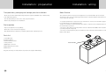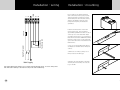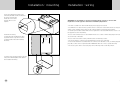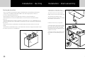
1
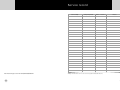
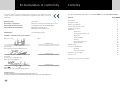
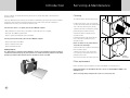
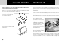
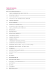
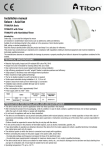
Installed By:
Date of Commissioning:
Commissioned By:
Boost Switch Method:
Boost Switch Location:
Ensure this booklet is passed to the householder once
installation and commissioning of the ventilation system
is complete.
This Product Manual must be kept in the Home
Information Pack and used as a service record (page 27).
MARKETING DIVISION
International House, Peartree Road, Stanway, Colchester, Essex CO3 0JL
Tel: +44 (0) 1206 713800 Fax: +44 (0) 1206 543126
Email: [email protected] Web: www.titon.com
BM 822 Iss 01
Titon HRV1
Heat Recovery Ventilation Unit
Product Manual
Service record
Serviced By
PCT Patent Application No PCT/GB2009/000114
2
Company Name
Date of Service
Notes
Always ensure the service record is logged in the table above.
27
EC Declaration of conformity
We declare that the equipment detailed below conforms to the requirements of EC
Contents
This Product Manual only relates to the Titon HRV1 (not the Titon HRV1 Q Plus)
council directives relating to electromagnetic compatibility and safety of electrical
Section
equipment.
Equipment type:
Description of equipment:
Introduction
Titon HRV1
Mechanical ventilation unit with heat recovery
Relevant EC Council Directives:
2006/95/EC (LVD), 2004/108/EC (EMC)
Applied Harmonised Standards:
EN 60335-1:2002/A2:2006
EN 60335-2-80:2003/A1:2004
Manufacturer:
Titon Hardware Limited
Signature of manufacturer representatives:
Name / Position
Page Number
Date
05 May 2009
5
How the system works
6
How to safely use the system
7
System specification
7
Installation
8
- Dimensions
8
- Pre-installation inspection
9
- Mounting
11
- Drain assembly
13
- Ducting
15
- Electrical connections
17
- Wiring diagram
Commissioning
Service and Maintenance
N C Howlett
Development and Sustainability Director
- Cleaning
- Filter replacement
05 May 2009
P S Cowell
Research and Testing Manager
BEng (Hons) CEng MCIBSE
4
Ventilation is vital
18
20
24
25
25
Declaration of conformity
26
Service record
27
Details Correct at the time of printing
05 May 2009
R Brighton
Managing Director - Manufacturing Division
MARKETING DIVISION
International House, Peartree Road, Stanway, Colchester, Essex CO3 0JL
Tel: +44 (0) 1206 713800 Fax: +44 (0) 1206 543126 Email: [email protected] Web: www.titon.com
26
3
Introduction
Interior comfort, air quality and energy efficiency are vitally important considerations in
buildings today.
Servicing & Maintenance
Cleaning
To clean the filters and heat exchanger:
The Titon HRV1 has been developed to meet these demands by providing clean fresh air whilst
extracting stale polluted air from the building using a state of the art heat exchanger to
maximise the recovery of heat from the extracted air.
For the home owner or occupant, this Product Manual explains:
1. Remove the front cover (see page 24).
2. Slide out the filters that are fitted either
side of the heat exchanger as shown.
3. Remove the heat exchanger by gently
• Why ventilation is vital for the good health of your home and its occupants.
pulling the plastic band around it.
• How your Titon HRV1 system works.
4. Clean the filters carefully using a
• How to operate and maintain your Titon HRV1.
vacuum cleaner.
Filters
5. Carefully remove any dust from the
For the professional installer, this Product Manual explains:
• How to install the Titon HRV1.
• How to commission the unit.
• How to maintain the unit.
face of the heat exchanger using a
vacuum cleaner.
Never use water or any other fl uids to
clean the heat exchanger.
6. Return the heat exchanger and filters to
Safety Notice
their original position.
It is important to read this Product Manual to ensure your ventilation system is installed,
commissioned and used properly and continues to operate effectively. Failure to follow the
guidance provided in this manual can have an adverse effect on health.
7. Replace the front cover and ensure
it is securely located at the top before
tightening all screws.
8. Power to the unit can now be restored.
Heat
Exchanger
Filter replacement
Filters should be replaced annually or after a maximum of 3 cleaning cycles.
Replacement filters are available from Titon, call us on +44 (0) 1206 713800 or via
www.titon.com
After servicing, always complete the service record on page 27.
4
25
Servicing & Maintenance
WARNING: The unit uses a 230V ~ supply and contains rotating mechanical parts.
ISOLATE the unit from mains power supply and allow sufficient time for all moving parts to
stop before undergoing any Servicing or Maintenance.
The air filters and heat exchanger of the Titon HRV1 should be cleaned regularly by a suitably
qualified person (the frequency of cleaning will vary depending on the installation environment).
Filters should be replaced after a maximum of 3 cleaning cycles.
Construction methods used in older homes resulted in uncontrolled ventilation via air leaking
through the building structure, such as small gaps around windows and doors or between walls
and floors. These leaks allowed a large amount of air to move through a house largely unnoticed
by the occupants. Other factors, such as open fireplaces, people being at home more often and
opening windows to “air” rooms during daytime, all helped maintain reasonable levels of air
quality in homes.
However, because this form of ventilation was uncontrolled, a large proportion of heat escaped
to the outside and more fuel energy (such as coal gas or electricity) was needed to make up for
this loss.
Filter and Heat Exchanger access:
1. Loosen the two corner screws located
on the bottom front of the unit.
Modern homes have virtually no air leaks and combined with improved levels of insulation, the
air indoors will not change without the use of products made to control ventilation.
Lack of ventilation in buildings will lead to the build up of harmful substances such as chemicals
and gases which come from the
everyday things we all have or use in
our homes that can go unnoticed for
long periods.
2. Remove the centre screw.
Moisture produced by people from
breathing and carrying out ordinary
activities such as washing or cleaning,
can build up and cause mould,
damaging the health of the occupants
and the building structure. A family
of four can produce up to 20 litres of
water vapour everyday.
3. Completely remove the front cover by
pulling it away from the unit at the bottom
and lifting upwards.
2
1
100
mm
24
Ventilation is vital
MA
X
Poor ventilation can be a major
contributory factor of heart disease,
lung disease, mental illness and many
more threats to our health.
The World Health Organisation and responsible Governments throughout the world recognise
the vital importance of good indoor air quality, and that is why Regulations govern the way
new houses are designed and built to ensure your health does not suffer as a result of poor
ventilation. When new homes are occupied, it is then up the people who live in them to make sure
they use and maintain the ventilation products in accordance with the instructions provided.
5
How the system works
Notes
The Titon HRV1 works by continuously extracting stale polluted air from rooms where most
moisture is generated and providing fresh pre-warmed air taken from outside the house and
delivering it to other rooms, creating a flow of fresh, cleaner air throughout the house.
The air travels from terminals built into the ceiling which are connected by hidden ducts to the
unit. The unit is usually installed in a roof space or cupboard.
Each unit is commissioned individually so the amount of air moved is set to suit the specifi c size
and style of the house.
Most systems will also have a facility to boost the extraction rate at times when more moisture is
being generated, such as when bathing or cooking. This may be done automatically by electronic
sensors or by a conveniently located boost switch for manual operation.
DO NOT switch off the unit; it is designed to run continuously. If the unit is switched off
indoor pollutant and moisture levels may increase and become a danger to your health and
damage your house.
It is important to follow the advice in this user manual and correctly maintain the system
to ensure a healthy indoor environment.
Typical system layout
The unit runs automatically and should not be switched off, except for maintenance or filter
replacement.
If a boost switch has been installed, it can be used to increase the extract ventilation rate at
times when moisture or pollutant levels are considered excessive.
6
23
Sketch
How to safely use the system
You may have electronic sensors which detect high levels of moisture and pollutants which boost
the system automatically.
All whole house ventilation units require periodic maintenance and this must only be carried out
by a suitably qualified and competent person. See the Servicing and Maintenance section for
further details.
Features of the Titon HRV1
• Compact size.
• Easy installation mounting bracket.
• Standard 15mm fitting for condensate drain connection.
• The duct ports accept 100 and 125mm diameter ducting.
• Boost Control via a two-way switch.
22
7
Installation - before you begin
Commissioning
The Titon HRV1 is designed to be
fitted in to the roof space or a
cupboard. These diagrams show
the dimensions of the unit and the
additional space required around the
unit to allow for future servicing and
maintenance.
400
IMPORTANT: READ THESE INSTRUCTIONS FULLY BEFORE THE INSTALLATION OF THIS
APPLIANCE!
NEVER install the unit in an area
which does not have suffi cient
access for future maintenance
NEVER install the appliance in an
environment which contains:
• Excessive oil or a grease laden
WHITE wire continuous rate, BLACK wire boost rate. Do not reposition the BROWN or BLUE wire.
environment.
250
• Hazardous gases, liquids or
Speed
Volts
1
100
2
140
3
160
4
180
5
200
corrosive.
• Ambient temperatures above 40°C
200
or below -5°C.
• Humidity levels above 90% or a
Curve
wet environment.
Static Pressure Pa
vapours that are flammable or
150
100
50
0
0
8
10
20
30
40
Volume Flow l/s
50
60
21
Commissioning
Once the appliance has been fully installed it must be commissioned
The HRV1 is Factory set at Continuous Speed 1 - 100V, Boost Speed 3 - 160V (see page 21).
Fan speeds may require adjustment in order to provide other ventilation rates more
appropriate to the dwelling.
Installation - preparation
Safety and guidance
• The electrical installation of the appliance MUST be carried out by a suitably qualified
competent person in accordance with current I.E.E. Regulations and all appropriate standards.
• The appliance must be connected to a local isolation switch with a contact separation of at
least 3mm.
If adjustment is required follow the steps below;
• The appliance is suitable for 230V ~ 50Hz single phase with a fuse rating of 3A.
• The condensation drain must be fitted.
• Isolate the appliance from the mains power supply.
• Ensure that external grills are located away from any fl ue outlet, in accordance with the
• Open the transformer access panel on the top of the unit.
relevant Building Regulations.
• Reposition the crimped connectors on the transformer to select an alternative continuous/
boost speed setting. WHITE wire continuous rate, BLACK wire boost rate. Do not reposition the
BLUE or BROWN wire. See page 21.
• Refit the transformer access panel and ensure that all covers and fixings are secure before
reconnection of the mains power supply.
• Always ensure ducting is free from blockages before switching the unit on as this may
invalidate your guarantee.
• Recommended a minimum distance of 2m between the external air supply inlet and the extract
air outlet to prevent cross contamination.
• Recommend a minimum distance of 200mm between the appliance and any sharp bends in duct
• Check the new speed settings.
work.
Installation of the appliance MUST be carried out by a qualified and suitably competent
person and should be carried out in clean, dry conditions where dust and humidity are at
minimal levels. The appliance is not suitable for installation to the exterior of the dwelling.
Transformer access
20
9
Installation - preparation
Installation - wiring
Transportation, packaging and storage prior to installation
Boost Control
• Great care should be taken when transporting the appliance, DO NOT drop as damage may
The continuous and boost speeds of the appliance are set at installation by selecting the
appropriate connections to a multi-tapped transformer located beneath the transformer access
cover on the top of the unit.
occur within the appliance.
• The unit must always be stored in a clean, dry environment.
• Remove all packaging before installation.
• A separate terminal box is fitted on the top of the unit for connection of the mains supply and
boost switch wiring. (See illustration below)
Pre-inspection
• Cable access must be via the preformed cable entries on the enclosure (suitable strain relief for
the cable must be provided)
• Inspect the appliance for any damage.
• The boost control utilises a two-way switch connection between the COM, L1 and L2 terminals
(see wiring diagram on Page 18).
• Check all accessories have been supplied.
• Any damage must be repaired by a suitably qualified and competent person.
• The boost can be triggered by any device which provides a two-way switch suitable for a 230V
mains power supply.
Parts list
1 Titon HRV1 unit.
4 Transport Bungs
2 Wall mounting brackets.
1 Safety bracket.
Terminal Box
1 15mm Drain connector.
4 M6x10mm pan head screws.
4 M6 washers.
Any parts shortages or faults must be reported to the supplier immediately.
10
19
L2
L1
COM
N
Double Pole Isolator
Boost Control
Two Way switch
3A Fuse
L
Installation - wiring
Installation - mounting
Do not remove the Transport Bungs
until connecting ducting (see page 15).
Transport bungs are fitted to prevent
debris falling into the unit and causing
damage. Premature removal of the
transport bungs may invalidate the
guarantee.
1. Mark a horizontal line on the wall
using a spirit level. This line will be
approximately 95mm below the location
of the top face of the unit when fitted
(excluding duct ports). It is recomended
that this line should be 495mm below the
finished ceiling level to create sufficient
space above the unit for installation and
maintenance.
2. Use one of the mounting brackets as
a template to mark the three fixing hole
centres.
N
L
3. Drill holes for fixings, always use a
fixing suited to the wall type.
230V Supply
4. Mount one fixing bracket to the wall
ensuring the interlocking side is at the
top, as shown.
Important: Wiring must always be in accordance with the diagram above. Incorrect wiring of the
unit will result in damage to the internal components and void Warranty
18
11
Installation - mounting
5. Fix the remaining bracket to the
unit using the M6 screws and washers
provided, ensuring the
interlock side is at the
bottom. Do not overtighten.
Installation - wiring
WARNING: The unit MUST be earthed. Installation must conform to current I.E.E.
Regulations and all applicable standards and Building Regulations.
• The unit is suitable for 230V~50Hz Single phase supply fused at 3A.
• A terminal box is fitted on the top of the unit for connection of the mains and boost trigger
switch. Note: suitable strain relief for the cable(s) must be provided by the installer.
• A double pole isolation switch with contact separation of at least 3mm must be used to connect
the appliance to the fixed wiring.
6. Mount the unit by
locating the two mounting brackets
together. Ensure a positive location
is made between the two mounting
brackets.
• Boost controls must not be located within 1 metre of a cooker or where they may be affected by
excessive heat or moisture
Hook onto
wall bracket
• Boost controls should be clearly identified and conveniently located.
• The boost switch is connected to the terminal box on the top of the unit.
• Please note that the boost switch must be connected for the unit to run, see wiring diagram on
page 18 (a connection is required between COM and either L1 or L2 to operate the unit).
• The boost speed can be selected by any device which provides a two-way switch.
7. Fix the lower safety bracket as shown
using the remaining M6 screw, washer
and suitable wall fixing.
12
17
Installation - ducting
Installation - drain assembly
A drain must be connected to allow
condensation to be removed from the unit.
Ducting best practice
• The use of fl exible ducting must be kept to a minimum and it should always be pulled taut.
• If applicable, Fire Dampers MUST BE FITTED to duct work at appropriate locations in
The drain connection is made via the
15mm connection on the base of the unit.
accordance with Building Regulations.
• Ducting must be installed in such a way that resistance to airflow is minimised.
• Ducting terminals for Inlet and exhaust must be to the external air outside the building
envelope.
The drain must discharge into the
household drainage system via a U-bend,
which must act as an air lock.
• Inlet and exhaust ducts should be separated to ensure there is no cross contamination of air.
• Ducting in unheated spaces must always be insulated to prevent condensation forming within
the ducting.
1. Remove front cover (see page 24).
• Ducting joints must be permanently sealed with quality ducting tape and/or silicone type
sealant.
• Recommended a minimum distance of 2m between the external air supply inlet and the extract
air outlet to prevent cross contamination.
Fresh Out
Fresh In
Stale In
2. Insert the drain connector through the
base of the unit from the inside. Ensure
the drain connector forms a seal with
the moulded drain tray, applying silicone
sealant if necessary.
(The heat exchange cube and filters have
been removed for illustrative purposes
only).
Stale Out
16
13
Installation - drain assembly
2. Assemble the drain as indicated
through the bottom of the unit.
Installation - ducting
transport bungs from the duct ports.
125mm ducting fits to the outer of the
duct ports as shown.
Important note: The drain must
incorporate a U-bend to prevent air
penetration.
100mm ducting fits to the inner of the
duct ports as shown.
1. When the ducting has been installed and you are ready to connect the unit, remove the
14
15