1
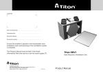
FUSION
HRV1 Mechanical Ventilation with Heat Recovery
Installation Instructions and User Manual
Commissioning Data: to be completed by installer
Date of installation:
Configuration
Left Hand
Right hand
Normal running speed %
Factory set to 44%
Installed to
Boost running speed %
Factory set to 66%
Installed to
Factory Setting
05.10.709
Contents
1. MVHR General Description/Physical Specifications
2
2. Installation Instructions
3
General Preparation
3
Positioning/Application
3
Condensate Drain
4
Mounting
4
Ducting Guidelines
4
Electrical
5
On Site Commissioning
6–9
3. User/Homeowner Information
9
LCD Display
9 Normal/Boost Operation
9 – 10
Timer and Humidity Controls
10
Indicators & Warnings
11
Maintenance (Filters/Heat Exchanger)
11
1.0 General Description/Physical Specifications
The HRV1 is a ventilation system designed to provide an improved indoor air quality in dwellings. As a whole house
system, the unit continuously extracts air from the non-habitable rooms and supplies fresh, filtered air to habitable rooms.
Heat that is recovered from the air drawn from the bathrooms and kitchen is passed through a heat exchanger and
the energy that is recovered is transferred, to temper the replacement air in habitable rooms to provide a comfortable
indoor environment.
Ancillary Items Required
• 125mm Ducting (100mm or rectangular ducting can be used, where appropriate)
• GS2 Switch providing switching between normal and boost
Physical Specifications
Front
Side
125mm Spigots
30
445
Filters
495
LCD Display
Condensate Ports
220
160
220
150
294.5
Top
600
90.75
HRV1
Installation Instructions and User Manual
2.0 Installation Instructions
2.1 General Preparation
The HRV1 unit is supplied with 4 x 125mm spigots and template for positioning on ducts to unit for installation.
2.1.1 125mm OR 100mm ducting with connectors can be used (see ancillary section pg 1) to provide performance levels required
for compliance with Building Regulations. Please contact Greenwood Airvac Technical Services with any questions.
2.1.2 Installation of the HRV1 should be in accordance with the current editions of Building Regulations and BS7671: IEE
Wiring Regulations.
2.1.3 The design, material specification and installation must only be carried out by ‘competent persons’.
IMPORTANT NOTE
Gases from fuel-burning equipment must not be drawn into any living areas. If any room, where air is extracted, contains a fuel
burning appliance such as a central heating boiler, then either of the following should be undertaken:
– the flue must be of the room sealed or balanced flue type or;
– allowance must be made for an adequate supply of air into the room
2.2 Positioning
2.2.1 The unit must be installed vertically and wall mounted to enable effective condensate drainage in either a service cupboard
or secured to a vertical structure in the loft space. Duct spigots must be upright at top of unit.
2.2.2 It is not advisable to install the unit directly above a bedroom or living room ceiling, or in an area that is part of a living
area or bedroom.
2.2.3 Consideration must be given to access for servicing, maintenance and any fault diagnostics. Maintenance on the Heat
Exchange and Filters are required at 24 and 6 month intervals respectively.
2.2.4 The unit can be configured for right and left hand installation configuration (see fig. below).
Stale out
Fresh in
Stale in
Fresh out
Right Hand Configuration
Fresh out
Stale in
Fresh in
Stale out
Left Hand Configuration
Fig 1.
The HRV1 is factory set for right hand installation
The handing of the unit can be changed through the LCD display and does not require any internal changes.
If alternative configuration is required, follow instructions in commissioning section (para 2.8.2) after installation.
2.3 Condensate
It is important that any condensate MUST be drained away. The unit is provided with separate drain and blanking plugs
(installed depending on right/left hand configuration). The drain plug allows a condensate drain hose (22mm diameter) to be
push connected and mechanically secured (See Fig. 1 & 2).
2.3.1 The drain must have a continuous minimum fall of 6mm per 1m run and can either be chased into the wall or run
downwards from the unit into the nearest waste water network.
2.3.2 In some instances, a condensate connecting point will already be provided as part of the building design. The position of
this point, relative to where the HRV1 unit is to be installed should be checked for any connection misalignment and any
necessary adjustment made before proceeding any further.
Heat
Recovery
Unit
Condensate
drain
wall mounted installation
Fig 2.
IMPORTANT NOTE: The condensate drain must incorporate a U bend.
2.4 Mounting – Vertical Installation
A template is provided to aid positioning of ducts to unit.
2.4.1 The unit is supplied with two fixing brackets. Fix one to the wall and the other to the unit and mount the unit.
2.4.2 Two levelling screws are provided to ensure vertical installation.
2.4.3 Connect the drainage hose to the condensate drain connection and ensure that steps are taken to minimise the risk
of mechanical damage to the drainage pipework. Run the pipe internally as far as possible and insulate to protect against
freezing. Condensate drain should terminate to the waste water network or externally.
2.5 Duct and Duct Connections
Please refer to design drawings
2.5.1 Four 125mm nominal diameter spigots are provided for connection to ducting. These must be securely connected to supply
and exhaust ducts according to right and left hand configurations (see commissioning section to change configuration).
HRV1
Installation Instructions and User Manual
2.5.2 Flexible or rigid ducting must be used and must fit over the spigots. Flexible ducts must be kept to a minimum.
2.5.3 Where ducts are exposed in unheated areas, such as roof spaces, they must be insulated with at least 25mm of insulation.
2.5.4 If applicable, Fire Dampers MUST BE FITTED in accordance with Part B of the Building Regulations.
2.5.5 Rigid Ducting
Install using the least number of fittings to minimise resistance to air flow. Where possible, final connection to grilles and
unit should be made with a flexible connection.
2.5.6 Flexible Ducting
Ensure ducting lengths are kept to minimum and ducting is pulled taut so that it is smooth and straight. Where bends are
necessary and where ducting is run in restricted areas, ensure the ducting is not crushed.
2.5.7 The inlet fresh air supply should be directly from the outside. If supplied through a wall, an external grille should be
supplied. If supplied through a roof, a recognised roof terminal should be supplied.
2.5.8 The exhaust air must exit to the outside through a wall or roof and must be protected by a wall grille or recognised
roof terminal.
2.5.9 Inlet and exhaust pipes should be installed at least 2m apart to avoid the cross contamination of airflows.
2.7 Electrical
WARNING:
The appliance MUST be earthed. All wiring must conform to BS 7671: IEE Wiring Regulations.
2.7.1 The unit is suitable for 230V~50Hz single phase supply fused at 3A.
2.7.2 The unit is supplied with a mains flexible cord (PVC sheathed, 4-core brown, blue, black. green/yellow 0.75mm²)
connected to a terminal block and exiting through a grommet and cable clamp at the right hand top of the unit.
2.7.3 A double-pole switch having a minimum contact separation of 3.0mm, must be used to provide isolation for the unit.
2.7.4 The recommended switch for use with the HRV1 is the Greenwood Airvac GS2.
Note: The switch terminal markings differ according to manufacturer.
Remote Switch Positions
Function
Normal (I)
Both fans running at normal speed (unless supply fan is disabled)
Boost (II)
Both fans running at full speed (unless supply fan is disabled)
I
2.7.5 The fan speed control must not be mounted above or closer that 1m to the cooker where is could be affected by excessive heat or moisture.
II
GS2 Fan Speed Control
230V/1Ph/50Hz
2.7.6 Wiring Diagram
E
N
L
Double-Pole
Isolator
3 amp
Fuse
Boost
Switch
(GS2)
E
Green/Yellow
N
Blue
L
Brown
SL
Black
Flying Lead from
HRV1 (terminating
into external
connector box)
Connector box for
mains voltage cabling
(not supplied)
2.8 On Site Commissioning
This section covers set-up, configuration of the unit on installation and altering pre-set factory settings. For instructions on how
to operate the LCD display including initiating the boost mode, maintenance options and indicator warning information, please
refer to the user manual section on page 9.
When in the configuration mode press [Boost/Exit] to go back to previous setting or screen and [OK] to go forward. To exit
configuration mode at any time press [OK] repeatedly until normal running screen appears.
2.8.1LCD Display
OVERRUN TIMER
HUMIDITY SENSOR
MAINTENANCE FILTER WARNING
DELAY TIMER
INTAKE FAN
ENABLE/DISABLE
SWITCHED LIVE MODE
MAINTENANCE MODE
FILTER
MAINTENANCE BAR
FAN WARNING
INDICATOR
FAN WARNING
INDICATOR
INTAKE FAN STATUS
(animated display)
INTAKE
:
.
HEAT EXCHANGER
MAINTENANCE WARNING
HEAT EXCHANGER
%
EXHAUST FAN STATUS
(animated display)
l/s
m
EXHAUST
DIGITAL READOUT
HEAT EXCHANGER MAINTENANCE BAR
2.8.2Software Revision Display
When power is first applied to the unit, it will display all symbols and then briefly show
the software revision as opposite. The unit will then revert to running mode using
factory set speeds.
2.8.3Left and Right Handed Configuration
The unit is factory set as a RIGHT HAND configuration with Fan 1 (left) Fresh Air Out
and Fan 2 (right) Stale Air Out.
To change the configuration:
i.
Select configuration mode by pressing and HOLDING DOWN [OK] then press
boost/exit button.
ii. Enter Pin Code – 1309 by using the (–) and (+) buttons and pressing ok after
each digit for access to configuration settings. If incorrect pin is entered the
normal running screen will return. If so, return to step 1.
:
1:2 Right hand, 2:1 Left hand
ii. Press the [–] or [+] button to swap the fans and readout on the LCD display
iii. When the setting is correct press [OK]
iv. Ensure the condensate drain plug and blanking plate are in the correct
pipes on the unit in accordance with the configuration.
:
.
%
The display should now show the opposite:
Note: As it takes a few seconds for the fans to accelerate to
normal running speeds, both fans may show warning symbols
for a few seconds when the unit is first powered up.
HRV1
Installation Instructions and User Manual
2.8.4 Setting ‘Normal Running’ Speed
The normal running speed is FACTORY SET AT 44% for intake and exhaust fans. These can be altered in steps of 1%
thus you can adjust the fan speed whilst measuring the airflow at the ducting.
Please note that the normal running speeds cannot be set higher than the boost speeds or vice versa (boost speeds
lower than normal speed).
To change the configuration to normal speed:
i. Initially, the left hand readout will be flashing
ii. Alter the intake running speed by using the [+] or [–] buttons accordingly
iii. Press [OK] to select the right hand readout (the image will start to flash)
:
.
%
iv. Alter the extract running speed by using the [+] or [–] button accordingly
v. When adjustment is completed, press [OK].
2.8.5 Altering the ‘Boost Running’ Speed
The boost running speed is FACTORY SET AT 66% for intake and exhaust fans. These can be altered in steps of 1%
thus you can adjust the fan speed whilst measuring the airflow at the ducting.
Following the set up of the normal speed, the display should now be as
opposite and the left hand readout should be flashing:
To change the boost speed settings, use the instructions as above for the
‘normal’ running speed.
:
.
%
When desired settings have been achieved press [OK], when the right hand
readout is flashing and the unit will advance to the run time counter display.
2.8.6 Run Time Counters
The unit records its run-time hours, which are displayed in two separate screens as follows:
The first screen shows years:months. This example represents
0 years and 11 months.
Press [OK] to advance to the next screen (all other buttons
have no effect).
:
The second screen displays days:hours.
The example below represents 24 days and 13 hours.
Press [OK] on this screen to exit configuration mode
and return to normal running status.
:
Note:
1. One month = 30 days (for the purpose of the run-time counter)
2. Run-time counters are written to memory once a day only, so in the event of a power failure, the hours only on
that day will be lost
3. The run-time counters are set to zero at manufacture and cannot be reset.
2.8.7 Altering Factory Settings
Symbols (from left to right)
Intake fan enable/disable
Overrun Timer Set
Factory Settings
Humidity Threshold Set
Delay Timer Set
Maintenance
Altering Factory Setting Options
Delay Timer
2 mins
1 – 5 mins (in steps of 1 minute)
Overrun Timer
10mins
10 – 30 mins (in steps of 5 minutes)
Humidity Activation Level
65%
50 – 99% ( in steps of 5%)
i. To adjust the user settings, press [–] or [+] buttons accordingly
ii. The display will illuminate and change to show the following
(where the left most icon will be flashing)
iii. To select an icon use the [–] and [+] buttons to move left & right
(the selected icon will flash)
iv. To alter the selected icon, press [OK].
The display will then change to show just the selected icon and the current factory set value (except for intake fan disable
and maintenance – see later sections).
Examples of screen display as opposite:
i. Each setting can be altered by using the [–] and [+] buttons
ii. When finished press [OK] to exit to previous screen or press [boost/exit] to
return to normal operation screen.
Note: If no buttons are pressed for 10 seconds, the display will revert to normal
running mode (except in maintenance mode).
m
%
m
HRV1
Installation Instructions and User Manual
2.8.8 Intake Fan Enable/Disable
The Intake fan, supplying replacement air to habitable rooms can be disabled in summer months to reduce the amount of
tempered air into the dwelling. It can then be enabled during winter months as required.
Select the intake fan enable/disable icon. The display will change to show the ICON ONLY.
i. Press the [–] button to disable the intake fan
ii. A cross will appear next to the icon as displayed opposite to show the intake fan
is disabled
The display will revert to normal operation without any further operator intervention,
and the icon with the cross will remain on display. In addition, the fan blades of the
intake fan icon will stop moving and appear as opposite.
%
To enable the fan again, repeat the operation but press [+] at step 1 above
Note:
All settings are stored in the memory and will NOT be lost in the event of a power failure. When power is restored, the
unit will revert to normal running with all settings unchanged. Likewise, reminder indicators are NOT reset.
3.0 User/Homeowner Information
The user manual provides an overview…..
3.1.1 LCD Display
OVERRUN TIMER
HUMIDITY SENSOR
MAINTENANCE FILTER WARNING
INTAKE FAN
ENABLE/DISABLE
DELAY TIMER
SWITCHED LIVE MODE
MAINTENANCE MODE
FILTER
MAINTENANCE BAR
FAN WARNING
INDICATOR
FAN WARNING
INDICATOR
INTAKE FAN STATUS
(animated display)
INTAKE
:
.
HEAT EXCHANGER
MAINTENANCE WARNING
HEAT EXCHANGER
DIGITAL READOUT
%
EXHAUST FAN STATUS
(animated display)
l/s
m
EXHAUST
HEAT EXCHANGER MAINTENANCE BAR
3.1.2 Normal Operation Display
EXHAUST FAN
STATUS
(animated
display)
Two fan icons ‘rotate’ slowly in normal mode
and more quickly in boost mode.
%
INTAKE FAN STATUS
(animated display)
HUMIDITY READOUT
3.1.3 Boost Mode (included switch icon next to boost mode)
%
3.1.4 Delay Timer
i.
Press [boost/exit] or trigger the ‘switched live’ input, via the installed boost
switch (wall mounted switch or light switch).
ii.
The switch icon appears in the display as indicated
iii.
The fan will then accelerate to the preset ‘boost’ speed
which also activates the DELAY TIMER
see below.
& Overrun Timer
Delay Timer: Factory set to 2 mins
%
i.
If the boost mode is cancelled BEFORE 2 mins, the fans will return
to normal speed immediately
ii.
If the delay timer expires, the icon will appear in the display as opposite.
Overrun Timer: Factory set to 10 mins
%
i.
If the boost is cancelled when the delay timer icon is displayed, the fan will
run at ‘boost’ speed until the pre-set overrun timer expires.
ii.
During this time, the overrun timer icon will appear on the display
as indicated.
3.1.5 Humidity Sensor
Humidity Sensor: Factory set to 65%
The humidity sensor monitors the humidity of the extracted air at all times.
If this exceeds the pre-set threshold, the fans will automatically switch to ‘boost
mode’ and the humidity icon will appear on the display as opposite.
%
When the humidity falls below the pre-set threshold, the overrun timer is activated to
further reduce humidity levels.
3.1.6 Indicators & Warnings
Filter and heat exchanger cleaning reminders are shown at all times
Once all of the bars have disappeared (1 per month for filters, 1 per 4 months for
heat exchanger), warning symbols will appear on display as opposite.
%
10
HRV1
Installation Instructions and User Manual
If a fan fails, a warning symbol against the faulty fan will appear on the display as
opposite.
%
NOTE: Warning symbols will sometimes show momentarily whilst fans are
attaining speed. This is normal.
3.1.7 Maintenance
WARNING
The HRV1 unit must be disconnected from the mains electrical supply before carrying out any maintenance work.
MAINTENANCE FILTER WARNING
Filters should be cleaned at 6 monthly intervals to ensure the unit works to
maximum performance. When a six month period has expired, the Filter warning
indicator will flash on the LCD display. Heat Exchanger should be maintained every
2 years, the heat exchanger warning indicator will flash on the LCD display.
Filters
Pull both of the filters out of the unit using the handles. Remove the filter covers,
wash and dry and then replace in unit.
%
HEAT EXCHANGER MAINTENANCE WARNING
Cleaning for Heat Exchanger
Isolate power to the unit before accessing the heat exchanger. Remove filters and
front cover via 6 screws. The heat exchanger can be simply pulled out and washed
with warm soapy water. Once dry, replace in original position.
When Filters and Heat Exchangers Servicing has been completed
i.
To adjust the user settings, press [-] and [+] button
ii.
The display will illuminate (whereby the left most icon will be flashing)
iii.
To select an icon use the [-] and [+] buttons to move left & right
(the selected icon will flash)
iv.
To alter the selected icon, press [OK]
v.
The display will change as opposite.
NOTE
Selecting the Maintenance Function will STOP both fans. Both the filter and heat exchanger indicators need amending.
Filters
i.
The shortest bar of BOTH filters indicators will be flashing
ii.
Use the [+] buttons to increase/decrease visible bars on indicator
iii.
Each bar corresponds to 1 month of run time (however, you may wish to
set a shorter service interval, for instance if the environment is very dusty)
iv.
Press [OK] once completed.
Heat Exchanger
i.
The shortest bar of the heat exchanger will now be flashing
ii.
Use the [+] buttons to increase/decrease visible bars on indicator
iii.
Press [OK] once completed
iv.
The unit will then exit maintenance mode.
11
The Guarantee Period
This Greenwood product (Fusion HRV1) is guaranteed for a period of 2 years from the date of purchase of the Product against
fault in manufacture. In case of such fault in manufacture apparent during the Guarantee Period, Greenwood may, at its absolute
discretion, repair the product, replace the product free of charge or refund the cost of the product AS LONG AS AND ONLY IF:
1. The Product is returned to Greenwood within the Guarantee Period with evidence of purchase date;
2. The Product has not been misused or handled carelessly or used on an inappropriate voltage supply;
3. Repairs have not been attempted other than by Greenwood’s service staff or authorised dealers; and
4. In Greenwood’s sole discretion, the Product is found to be faulty. If it were not found to be faulty, the Product would be
available for collection from the relevant Greenwood’s premises within one calendar month and if it was not collected, it
would be subsequently delivered by Greenwood and a delivery charge will be made. (the guarantee)
This guarantee does not confer any rights other than those expressly set out above and does not cover any claims for
consequential loss, damage or any costs incurred in the replacement of the faulty Product.
This Guarantee is offered as an extra benefit and does not affect your statutory right as a consumer.
All information believed correct at time of going to press.
All goods are sold according to Greenwood Air Management Ltd’s Standard Conditions of Sale which are available on request. All dimensions in millimetres unless otherwise shown.
Greenwood Air Management Ltd reserves the right to change specifications and prices without prior notice.
© Copyright Greenwood Air Management Ltd 2006.
Greenwood Air Management Ltd Greenwood House, Brookside Avenue, Rustington, West Sussex, BN16 3LF.
Tel: +44 (0) 1903 771021 Fax: +44 (0) 1903 777122 Email: [email protected] Web: www.greenwood.co.uk or www.partf.com


![4403002491_712_716 menu_EN_A [s]](http://vs1.manualzilla.com/store/data/005650300_1-96030b29e24dd373b0bced3bef593dda-150x150.png)