1
Midas Gas Detector
Operating Instructions
•
•
•
•
•
•
•
TOC
General Description
Product Overview
Default Configuration
Installation
Detector Start-up
General Operation
•
•
•
•
•
•
•
Navigating Menus
Routine Maintenance
Pyrolyzer Module Options
LonWorks® Interface
Troubleshooting/Faults
Reflex®
Internal Web Server
•
•
•
•
•
•
•
Installation Topologies
Ordering Information
Specifications
Calibration/Bump Testing
Modbus/TCP Interface
Gas Tables
Warranty
Midas® Gas Detector
Table of Contents
Contents
1 General Description
1 General Description�������������������������������������������������������������������������������������������������������� 1-2
2 Product Overview
2 Product Overview����������������������������������������������������������������������������������������������������������� 2-2
2.1 Main Chassis���������������������������������������������������������������������������������������������������������� 2-2
2.1.1 Display������������������������������������������������������������������������������������������������������������ 2-2
2.1.2 Pump Module�������������������������������������������������������������������������������������������������� 2-3
2.1.3 Sensor Cartridge Chamber����������������������������������������������������������������������������� 2-3
2.2 Mounting Bracket Assembly��������������������������������������������������������������������������������� 2-3
2.2.1 Mounting Bracket�������������������������������������������������������������������������������������������� 2-4
2.2.2 Terminal Module���������������������������������������������������������������������������������������������� 2-4
2.3 Sensor Cartridge ��������������������������������������������������������������������������������������������������� 2-4
2.3.1 Biased Sensor Cartridges������������������������������������������������������������������������������� 2-4
2.4 Cover����������������������������������������������������������������������������������������������������������������������� 2-5
3 Default Configuration
3 Default Configuration����������������������������������������������������������������������������������������������������� 3-2
4 Installation
4 Installation����������������������������������������������������������������������������������������������������������������������� 4-2
4.1 Mounting and Location of Detector��������������������������������������������������������������������� 4-2
4.2 Mechanical Installation������������������������������������������������������������������������������������������ 4-4
4.3 Sample and Exhaust Tubing Calculations���������������������������������������������������������� 4-7
4.4 In-line Filters����������������������������������������������������������������������������������������������������������� 4-8
4.5 Local Detector Option������������������������������������������������������������������������������������������� 4-8
4.6 Electrical Installation��������������������������������������������������������������������������������������������� 4-8
4.7 Electrical Connections���������������������������������������������������������������������������������������� 4-11
4.8 Refitting the Main Chassis���������������������������������������������������������������������������������� 4-23
4.9 Installing the Sensor Cartridge��������������������������������������������������������������������������� 4-23
5 Detector Start-Up Procedures
5 Detector Start Up Procedures��������������������������������������������������������������������������������������� 5-2
Midas Technical Handbook
i
Midas® Gas Detector
6 General Operation
6 General Operation���������������������������������������������������������������������������������������������������������� 6-2
6.1 Normal Operation Mode ���������������������������������������������������������������������������� 6-2
6.1.1 Resetting Alarms, and Faults�������������������������������������������������������������������������� 6-4
6.2 Review Mode ����������������������������������������������������������������������������������������������������������������� 6-4
6.2.1 Review Mode Menu Overview
������������������������������������������������������������������� 6-4
6.3 Overview of Set-up, Calibration and Test Mode ������������������������������������������������ 6-6
6.3.1 Set-up Menu Overview
������������������������������������������������������������������������������ 6-6
6.3.2 Calibration Menu Overview ‘ CAL’�������������������������������������������������������������������������6-8
6.3.3 Test Menu Overview ‘
tESt’������������������������������������������������������������������������ 6-9
7 Detailed Procedures for Navigating Mode Submenus
7 Detailed Procedures for
Navigating Mode Submenus���������������������������������������������������������������������������������������������������7-2
7.1 Review Mode
���������������������������������������������������������������������������������������������������� 7-2
7.1.1 Review Software ‘SW’������������������������������������������������������������������������������������� 7-2
7.1.2 Review Alarms ‘ ALm’���������������������������������������������������������������������������������� 7-2
7.1.3 Review Faults ‘
FLt’������������������������������������������������������������������������������������� 7-3
7.1.4 Review Calibration ‘ CAL’�������������������������������������������������������������������������������� 7-3
7.1.5 Review Date and Time ‘timE’��������������������������������������������������������������������������� 7-3
7.1.6 Review Detector Address ‘ nEt’�������������������������������������������������������������������� 7-3
7.1.7 Review Event Log ‘
Hi St’�������������������������������������������������������������������������� 7-4
7.1.8 Review LCD Backlight Mode ‘LCD’����������������������������������������������������������������� 7-4
7.2 Set-up, Calibration and Test Modes �������������������������������������������������������������������� 7-4
7.2.1 Set-up Menu ‘ SEt’���������������������������������������������������������������������������������������� 7-5
7.2.2 Set Alarms ‘ ALm’������������������������������������������������������������������������������������������ 7-5
7.2.3 Set Faults ‘ FLt’���������������������������������������������������������������������������������������������� 7-6
7.2.4 Set Calibration Interval ‘ CAL’������������������������������������������������������������������������� 7-7
7.2.5 Set Date and Time ‘timE’��������������������������������������������������������������������������������� 7-7
7.2.6 Set Address ‘ nEt’���������������������������������������������������������������������������������������� 7-8
7.2.7 Set pass code ‘ PWd’������������������������������������������������������������������������������������ 7-8
7.2.8 Set LCD Backlight mode��������������������������������������������������������������������������������� 7-9
Midas Technical Handbook
ii
Midas® Gas Detector
7.2.9 Set Pump control frequency���������������������������������������������������������������������������� 7-9
7.3 Calibration Menu ‘ CAL’������������������������������������������������������������������������������������ 7-10
7.3.1 Zero Calibration ‘ 0CAL’��������������������������������������������������������������������������������� 7-10
7.3.2 Span Calibration ‘ SPAn’������������������������������������������������������������������������������� 7-10
7.3.3 Flow Calibration ‘ FLoW’�������������������������������������������������������������������������������� 7-11
7.3.4 mA Calibration ‘mA 4-20’������������������������������������������������������������������������������� 7-12
7.4 Test Menu ‘
tESt’��������������������������������������������������������������������������������������������� 7-13
7.4.1 Bump Test ‘ bUmP’��������������������������������������������������������������������������������������� 7-13
7.4.2 Alarm/Fault Test ‘ SIm’�������������������������������������������������������������������������������� 7-13
7.4.3 Inhibit State ‘ InH’��������������������������������������������������������������������������������������� 7-14
7.4.4 Stimulate 4-20mA ‘4-20 mA’�������������������������������������������������������������������������� 7-14
8 Routine Maintenance
8 Routine Maintenance������������������������������������������������������������������������������������������������������ 8-2
8.1 Sensor Cartridge Replacement���������������������������������������������������������������������������� 8-3
8.1.1 Sensor Cartridge Fitting/Replacement������������������������������������������������������������ 8-3
8.2 Pump Replacement������������������������������������������������������������������������������������������������ 8-4
8.3 Reassembling the Detector����������������������������������������������������������������������������������� 8-5
8.4 Filter Replacement������������������������������������������������������������������������������������������������� 8-6
8.5 System Leak Check Procedure���������������������������������������������������������������������������� 8-7
9 Pyrolyzer Module Options
9 Pyrolyzer Module Options��������������������������������������������������������������������������������������������� 9-2
9.1 Fitting the Pyrolyzer Module��������������������������������������������������������������������������������� 9-4
9.2 Reassembling the Detector����������������������������������������������������������������������������������� 9-6
9.3 Configuring the Detector��������������������������������������������������������������������������������������� 9-7
9.4 Replacing the Pyrolyzer Heater Block����������������������������������������������������������������� 9-7
10 Optional LonWorks® Interface Installation
10 Midas LonWorks® Interface Module�������������������������������������������������������������������������� 10-2
10.1 LonWorks® Installation�������������������������������������������������������������������������������������� 10-2
10.1.1 Fitting the LonWorks® Module�������������������������������������������������������������������� 10-2
10.1.2 Wiring the Midas® for LonWorks® ��������������������������������������������������������������� 10-3
10.1.3 Configuring the Midas® for LonWorks® ������������������������������������������������������ 10-3
Midas Technical Handbook
iii
Midas® Gas Detector
10.2 LonWorks® Software ����������������������������������������������������������������������������������������� 10-4
10.2.1 LonWorks® Overview����������������������������������������������������������������������������������� 10-4
10.2.2 Network Variable Behaviors������������������������������������������������������������������������ 10-5
10.2.3 Other Characteristics���������������������������������������������������������������������������������� 10-9
11 Troubleshooting and Fault Diagnosis
11 Troubleshooting and Fault Diagnosis���������������������������������������������������������������������� 11-2
12 Reflex®
12 REFLEX® ��������������������������������������������������������������������������������������������������������������������� 12-2
13 Internal Web Server
13 Internal Web Server���������������������������������������������������������������������������������������������������� 13-2
13.1 Physical Network Components������������������������������������������������������������������������ 13-2
13.2 Internet Settings������������������������������������������������������������������������������������������������� 13-2
13.3 Running the Web Browser�������������������������������������������������������������������������������� 13-4
14 Typical Installation Topologies
14 Typical Installation Topologies��������������������������������������������������������������������������������� 14-2
14.1 Conventional Installation���������������������������������������������������������������������������������� 14-2
14.2 Modbus/TCP Installation����������������������������������������������������������������������������������� 14-3
14.3 Power over Ethernet (PoE) Installation������������������������������������������������������������ 14-3
15 Ordering Information
15 Ordering information�������������������������������������������������������������������������������������������������� 15-2
15.1 Midas® Transmitter�������������������������������������������������������������������������������������������� 15-2
15.2 Midas® Pyrolyzer for NF3 ���������������������������������������������������������������������������������� 15-2
15.3 Midas® High-Temperature Pyrolyzer for Perfluoro Compounds������������������� 15-2
15.4 Midas® LonWorks® Module������������������������������������������������������������������������������� 15-2
15.5 Midas® Complete Gas Detector Kits����������������������������������������������������������������� 15-3
15.6 Accessories and Spares����������������������������������������������������������������������������������� 15-4
16 Specifications
16 General Specifications����������������������������������������������������������������������������������������������� 16-2
17 Calibration and Bump Testing
17 Calibration and Bump Testing����������������������������������������������������������������������������������� 17-2
A Modbus® / TCP Interface
Midas Technical Handbook
iv
Midas® Gas Detector
A Modbus/TCP Interface���������������������������������������������������������������������������������������������������A-2
A.1 Reading Status from the Midas® �������������������������������������������������������������������������A-2
A.2 Sending Commands to the Midas® ���������������������������������������������������������������������A-5
A.3 Determining the MAC Address����������������������������������������������������������������������������A-6
B Gas Tables
C Warranty Statement
C Warranty Statement�������������������������������������������������������������������������������������������������������C-2
Sensor Cartridge Warranty ����������������������������������������������������������������������������������������C-3
Pyrolyzer Warranty �����������������������������������������������������������������������������������������������������C-3
Midas Technical Handbook
v
Midas® Gas Detector
1 General Description
Midas Technical Handbook
1-1
Midas® Gas Detector
1 General Description
The Midas® gas detector is an extractive gas sampling system that draws a sample locally or from a remote
point to a sensor cartridge that is located inside the detector’s chassis. A wide range of Asphyxiant, Toxic,
Flammable, Pyrophoric, Corrosive, and Oxidizer (including Oxygen) gas sensor cartridges are available that
enable detection of gases used or generated in the Semiconductor and other industries.
Midas® is wall mounted and displays gas concentration, alarm, fault and status information via its backlit LCD
and LEDs. A simple to use 4-button keypad located under the display provides the facility to set-up, review,
operate and make changes to the detector’s configuration.
Midas® has flexible power and communications capabilities built in as standard. These include 3 on board
relays, 0-21 mA analog output, Modbus/TCP outputs for signal and service connectivity as well as the innovative
Power over Ethernet (PoE) connection that enables a single Ethernet connection to be made for all power,
control and communication requirements. An optional LonWorks® interface is available.
Midas Technical Handbook
1-2
Midas® Gas Detector
2 Product Overview
Midas Technical Handbook
2-1
Midas® Gas Detector
2 Product Overview
2.1 Main Chassis
The Midas® gas detector comprises of 4 parts: the main
chassis, the mounting bracket assembly, the sensor
cartridge and the unit cover. Diagram 2-1 details the
Midas® general arrangement. Additionally, optional
Pyrolyzer modules for the detection of NF3 or various
PFCs and an optional LonWorks® module are available.
Please refer to Section 9 and 10 respectively for details
of these options.
The main chassis comprises of the display, pump
assembly, and plug in sensor cartridge chamber.
Diagram 2-2. Main chassis
Service Port
Display
Pump module
Diagram 2-1. Midas® general arrangement exploded view
Sensor cartridge chamber
Caution
? ? ???
The Service Port is only for use with
approved connectors by Honeywell
Analytics service personnel operating a
system diagnostic. Unauthorized connection
to this port may lead to damage of the
Midas® and external equipment and will not
be covered by the normal product warranty
conditions.
? ?? ?
? ? ?? ? ?
?? ? ???
?? ? ?
? ?? ? ?
? ?? ?
? ? ?? ?
? ? ??
??
? ? ???? ? ? ?
??
? ? ???? ? ? ?? ?? ? ?
?
? ?? ?? ? ? ? ? ? ? ?
?
?
?????? ? ???? ? ?? ? ??
?? ? ?
???
? ??
? ? ? ??
????
2.1.1 Display
The display is located at the front of the main chassis
and consists of a large alphanumerical and graphical
backlit LCD, 3 LED indicators and a 4-button keypad.
Under normal operation the LCD and LEDs display
gas concentration, alarm and system status. In set-up,
review, calibration and test modes, the LCD shows
the relevant menu options. These menus are simply
navigated using the ‘s’ up, ‘t’ down, ‘3’ accept and
‘X’ cancel buttons.
Midas Technical Handbook
2-2
Midas® Gas Detector
Diagram 2-3. Midas® display module layout 1.
1
1
1
1
3
1
1
5
7
1
2
2.
3.
4.
5.
6.
7.
8.
9.
1
4
1
6
8
MDA Scientific Midas
1
1
9
21
1
10
1
20
1
11
1
1
18
1
19
1
16
1
17
1
14
1
15
10.
11.
12.
13.
14.
15.
16.
17.
18.
12
1
13
19.
20.
2.1.2 Pump Module
21.
Red alarm LED
Normal operation icon
Review mode icon
Green power LED
Set-up mode icon
Calibration mode icon
Yellow Fault LED
Test mode icon
Gas concentration and
message display area
Displayed units
Pass code icon
Accept button
Network icon
Down button
Inhibit icon
Fault icon
Up button
Alarm level 1 icon s
Alarm level 2 icon
(For flammable and toxic)
Depletion level 1 icon t
Depletion alarm level 2
Cancel button
Zero and Span calibration
icons
Flow indicator
2.1.3 Sensor Cartridge Chamber
The sensor cartridge chamber is located at the front of
the main chassis below the display module. The plug
in sensor cartridge is fitted into this area which makes
the electrical connection between the sensor cartridge
and the rest of the electronics as well as providing the
chamber where the sensor cartridge is exposed to the
sampled gas. This connection is lightly lubricated for
ease of sensor replacement. Avoid contact of sensor
cartridge chamber with contaminants (such as dust
and debris). For details of fitting sensor cartridge refer
to Section 4.9.
2.2 Mounting Bracket Assembly
The mounting bracket assembly comprises of the
detector mounting bracket, the terminal module, the
gas sample inlet and outlet ports, the cable/conduit
entry and Ethernet (Modbus/TCP) communications
socket.
The pump module is located at the back of the main
chassis. It draws the gas sample from the inlet port
located at the bottom of the mounting bracket assembly
via an inline filter to the sensor cartridge chamber
located at the front of the main chassis. The inline filter
is to protect the elements after the sensor. The sample
goes from the inlet straight to the sensor face, and then
through the rest of the flow system. The sample is then
exhausted via the exhaust port located at the bottom
of the mounting bracket assembly. The pump and
filter assemblies are designed for easy replacement.
For replacement details refer to Sections 8.2 and 8.4
respectively.
Midas Technical Handbook
2-3
Diagram 2-4. Mounting bracket assembly
Mounting bracket
Terminal module
Gas inlet port
Cable entry
Gas outlet port
Ethernet/PoE socket
Midas® Gas Detector
2.2.1 Mounting Bracket
Diagram 2-5. Sensor cartridge
Protective Cap
(remove before use)
The metal mounting bracket has two slots that allow
the detector to be easily mounted to a wall using two
suitable screws (DIN rail or horizontal mounting options
are also available). For further details of mounting the
detector refer to Section 4.
2.2.2 Terminal Module
The terminal module is located on the mounting
bracket. All electrical connections to Midas® are made
via this module. Wire entry to the terminal module area
is via the PG16 cable entry/conduit entry located at
the bottom of the mounting bracket assembly.
2.3 Sensor Cartridge
A wide range of Flammable, Pyrophoric, Corrosive,
and Oxidizer (including Oxygen) sensor cartridges can
be fitted to Midas®. The plug in sensor cartridges are
fitted in the sensor cartridge chamber at the front of the
main chassis. To access the chamber the unit cover is
removed by unscrewing the thumbscrew located at the
front of the detector. The pre-calibrated smart sensor
cartridges can easily be fitted or replaced as they
simply plug into the detector without the need for any
tools. The sensor cartridge is firmly held in place by
two locking tabs. Some cartridges are shipped with a
protective cap to shield them from contaminants during
shipping. This cap must be removed before inserting
the cartridge into the Midas® unit, failure to do so may
damage the Midas® transmitter.
Connector
Locking tabs
REM
AT T OVE
INST IME OF
ALL
ATIO
N
Front
Back
2.3.1 Biased Sensor Cartridges
Some sensor cartridges are shipped with a battery
powered electrical supply in order to keep the cell
effectively ‘warmed up’ and ready to monitor once
installed in the Midas® unit. Battery powered bias
circuits are supplied for TEOS, NO, and CO2. The bias
circuit is removed just before insertion into the Midas®
system and the sensor cartridge is thus ready sooner
for effective gas detection.
Should a bias voltage not be applied (e.g. during
a power failure), the cell will take a longer time to
recover before effective gas detection can take place.
The longer the loss of applied power, the longer the
recovery time. During this recovery time, there is a
chance for false/inaccurate readings. Refer to the
relevant sensor cartridge data sheet for information
on each sensor cartridge.
In order to avoid the risk of loss of gas detection due
to unforeseen power loss, we recommend that a power
management solution such as uninterruptible power
supplies are used.
Midas Technical Handbook
2-4
Midas® Gas Detector
Note
Diagram 2-7. Midas® covers
Sensor warranty is void if the sensor cartridge
is opened by unauthorized user.
Diagram 2-6. Biased Sensor.
LED Windows
LCD Window
Pushbuttons
Sensor Cartridge
viewing window
Thumbscrew
Standard Cover
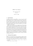
2.4 Cover
The standard cover provides environmental protection
and fits over the top, front and sides of the main
chassis. The front panel has viewing windows for the
LCD, LEDs and sensor cartridge fitted in the sensor
cartridge chamber. Underneath the LCD window are
the 4 push buttons used for navigating the detector’s
software menus. The cover is easily removed to allow
access to the chassis by unscrewing the thumbscrew
on the front panel and pulling the cover forwards off
the main chassis.
Midas units fitted with a pyrolyzer utilize a ventilated
cover due to the high temperatures generated by the
pyrolyzer unit (See Diagram 2-7)
Midas Technical Handbook
2-5
LED Windows
LCD Window
Pushbuttons
Sensor Cartridge
viewing window
Thumbscrew
Ventilated Pyrolyzer Cover
Midas® Gas Detector
3 Default Configuration
Midas Technical Handbook
3-1
Midas® Gas Detector
3 Default Configuration
As standard, the Midas® gas detector is factory configured as below:
Table 3-1. Midas® default configuration
1.0 mA
2.0 mA
3.0 mA
4.0 to 20.0 mA
21.0 mA
Current source with:
Fault
Inhibit
Maintenance Fault
Gas reading (normal operation)
Over range
Toxic Gas
Flammable Gas
Oxygen
Full Scale (FS)
Typically 4 x Threshold Limit
Value (TLV)
100% Lower Explosive Limit
(LEL) 1
25% Volume (v/v)
Lowest Alarm Level (LAL)
Typically 1/2 TLV
10% LEL
5% v/v
Lower Detectable Limit
(LDL)
Typically 0.4 TLV
9% LEL
0% v/v
The LDL is the minimum level that is reliably distinguishable from zero.
1/2 TLV
Alarm 1
(Relay 1)
10% LEL
23.5% v/v (Rising)
Normally de-energized, energizes on alarm.
Contact Normally Open (NO), closes on alarm.
TLV
Alarm 2
(Relay 2)
20% LEL
19.5% v/v (Falling)
Normally de-energized, energizes on alarm.
Contact Normally Open (NO), closes on alarm.
Fault
(Relay 3)
Normally energized, de-energizes on fault.
Contact Normally Open (NO). Instrument Fault Only
Latching
Latching. Alarm and fault relays DO NOT automatically reset when reading falls below alarm
thresholds. Relays MUST be manually reset.
Pass code
No pass code set.
IP Address
169.254.60.47 subnet mask 255.255.255.0
1
Midas® detectors are not ETL approved for monitoring in or sampling from classified areas above 25% LEL
See Table 7-3 for more information on Relay Configuration
Midas Technical Handbook
3-2
Midas® Gas Detector
4 Installation
Midas Technical Handbook
4-1
Midas® Gas Detector
4 Installation
4.1 Mounting and Location of Detector
For ease of installation Midas® has been designed
to allow the installation of the mounting bracket
assembly and terminal module separately from the
other parts of the detector. The detector location and
hard wiring can therefore be completed before fitting
the detector’s main chassis and sensor cartridge.
The Midas® gas detector has an integral mounting
bracket assembly that is easily mounted to a
suitable vertical surface such as a wall, tool housing,
mounting plate on a pole etc.
Drill Template
WARNING
Midas® is designed for installation and use in
indoor safe area non-explosive atmospheres.
Installation must be in accordance with the
recognized standards of the appropriate
authority in the country concerned. Prior
to carrying out any installation ensure local
regulations and site procedures are followed.
Drill 2 x
M4 holes
2.3 in
(58.50mm)
Diagram 4-1. Midas® outline dimensions
5.91 in [150.00mm]
MDA Scientific Midas
Note
z zellweger analytics
GAS DETECTOR
4.72 in [120.00mm]
honeywell
PN: MIDAS-E-CDX
SN: 12K-48397
Activate by 24-Nov-12
honeywell
2.48 in [63.00]
Midas Technical Handbook
4-2
This drill template is not to scale.
The Midas Quick Start Guide
(MIDAS-A-020) contains a full
scale drawing.
Ensure all measurements are
correct before using as an actual
drill template.
Use 2 x M4 Screws or equivalent
for mounting (head size 6-12
mm (1/4” - 1/2”))
Midas® Gas Detector
Midas® Transmitters and Pyrolyzers
3.9 in.
(205 mm)
6.0 in
(152 mm)
Midas-A-039
9.6 in.
(244 mm)
5.2 in.
(132 mm)
7.9 in
3.2 in (201 mm)
(81 mm)
Midas-T-OOP
3.9 in.
(98 mm)
3.2 in
(83 mm)
2.4 in.
(60 mm)
2.5 in
(62 mm)
MDA Scientific Midas
Midas-T-HTP
honeywell
2.3 in.
(59 mm)
PN: MIDAS-E-CDX
SN: 12K-48397
Activate by 24-Nov-12
honeywell
9.1 in.
(233 mm)
4.4 in.
(113 mm)
8.2 in.
(209 mm)
Note: Heat shield not present on all pyrolyzers.
Midas Technical Handbook
4-3
5.5 in.
(140 mm)
4.0 in.
(101 mm)
Midas® Gas Detector
Below are some considerations when installing the
Midas® Gas Detector:
1. Mount the detector on a surface that is flat,
firm and suitable for its size and weight.
2. Use the drill template supplied to drill the holes
for the fixings.
3. Use fasteners appropriate for the surface
being mounted to.
4. Ensure the head size of fastener used will not
snag the terminal PCB 6-12 mm (.25 in - .5 in).
5. Consider the conduit/cable weight and its
stress on the installation.
6. Position the detector so that it can be easily
accessed.
7. Position the detector so that it is at a suitable
height (normally eye level) for the display to
be clearly seen.
8. Take into consideration the space required
to remove the detector’s cover and locking/
unlocking the sensor cartridge locking clips.
Minimum recommended spacing between
multiple Midas® units is 82 mm (3.23 in).
9. Take into consideration the space required for
sample inlet and exhaust tubing (for remote
monitoring), and for the inlet filter (for local
monitoring).
10. Take into consideration the space required for
cable or conduit access.
Midas Technical Handbook
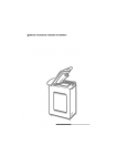
4.2 Mechanical Installation
The following steps and diagrams show how to separate
the mounting bracket assembly from the main chassis
and mount it on a vertical flat surface.
4-4
1. Unscrew the thumbscrew located on the front
panel.
2. Remove the cover by pulling it forwards off the
main chassis. Be sure to remove the internal
packing card securing the pump. Failure to
remove this packing will result in damage to
the Midas® unit. (See Diagram 4-2)
3. Unscrew the two retaining screws located at
the bottom front of the chassis.
4. Holding the mounting bracket assembly with
one hand use the other to carefully pull the
main chassis forward to disconnect it from the
mounting bracket assembly.
5. Using the drill template provided drill two holes
58.50 mm vertically apart for 2 x round head M4
fixing screws.
6. Partially screw the fixings into the mounting
surface.
7. Place the mounting bracket assembly over
the screws so they pass through the mounting
holes and then slide down to locate in the slots.
8. Tighten the screws to secure the mounting
bracket assembly.
Midas® Gas Detector
Diagram 4-2. Mechanical installation
chassis
Removing cover
Removing chassis
chassis
loosen
E!
OTIC
TN
TAN
OR
rnal
inte from
ove tion
Remprotec e brfore
ng odul
pi
ship mp m tion
la
pu
the instal
IMP
mounting
bracket
CE
OTI
TN
TAN
OR
rnal
inte from
ove tion
Remprotec e brfore
ping odul
ship mp m tion
la
pu
the instal
mounting
bracket
cover
!
IMP
Chassis Mounting Screws
Internal packing card
Remove before use.
Midas Technical Handbook
4-5
Internal packing card
Remove before use.
Midas® Gas Detector
Diagram 4-3. Mechanical installation
DIN Rail Bracket
Spacer Bracket
mounting bracket
screws
Standard Midas® Wall Mount
2x M4 Screws
Secures Midas® to
Spacer Bracket
4x M3 Screws
Secures DIN Rail
to Spacer Bracket
Optional Midas® DIN Rail
Mount (MIDAS-A-036)
Optional Midas® Pyrolyzer Adjustable “L” Bracket Mount
(MIDAS-A-032)
Note:
MDA Scientific Midas
When using the Adjustable
“L” bracket with the HighTemperature Pyrolyzer
unit, (2) Top Access Tubing
Connectors (MIDAS-A031) must be used to insure
proper operation.
honeywell
PN: MIDAS-E-CDX
SN: 12K-48397
Activate by 24-Nov-12
honeywell
Optional Midas® Adjustable “L” Bracket Mount
(MIDAS-A-032)
Top Access Tubing Connector
(MIDAS-A-031)
Midas Technical Handbook
4-6
Midas® Gas Detector
Note
4.3 Sample and Exhaust Tubing Calculations
Honeywell Analytics recommends the use of
Teflon FEP (Fluorinated Ethylene Polymer)
tubing to assure proper sample transport.
The properties of Teflon FEP make it the
best choice for transporting sample toxic
gases to instruments when compared with the
properties of other similar tubing materials.
The following tables show the flow rate, tubing
length, transport time, and maximum pressure and
vacuum at the inlet and exhaust points. Tubing
lengths vary among gases. See Appendix B for
recommended lengths.
Table 4-1. Inlet sample specifications
Inlet Sample Specifications:
Maximum
Tubing Length, m (ft)
30 (100)
20 (66)
10 (33)
0
Transport Time (sec), ID 1/8” 1
28
19
10
1
Transport Time (sec), ID 3/16”
63
43
23
1
Sample Point Vacuum
(Negative pressure)
-25.4 cm H2O (-10 in H2O) Maximum
Flow rate, cc/min.
If the pressure/vacuum on the inlet/exhaust lines
does not meet the recommended values in Tables
4-1 and 4-2, the following chart describes potential
fault conditions that may be brought on by the
external influences thus resulting in an F81 Flow
Fault.
External Flow
1
500 (Flow is constant) 2
Tubing OD, mm (in)
6.35 (0.25)
Tubing ID, mm (in)
3.18 (0.125)
2
1
Honeywell Analytics recommends the thick-wall tubing (1/8”
ID) for best speed of response.
Low
(0-150 cc/min)
Low
(0-150 cc/min)
Fluctuation
Fault 81
None
No
Yes
(up to 100 cc/min
flow swings)
Likely
3
Medium
(~200-450 cc/min)
Yes and No
Yes
Minimum flow rate for the
pump is ~300 cc/min. With this
external flow, the auto-adjust
cannot work because the pump
cannot produce a flow at this low
level. The problem is worse if
there are flow fluctuations.
4
High
(> 600 cc/min)
Yes and No
Yes
Midas ® cannot reduce the
external flow. Midas® will issue
Fault 81 due to high flow
The flow rate is electronically maintained at approximately
500 cc/min and may vary within acceptable tolerances.
Outlet Sample Specifications:
Maximum
Tubing Length, m (ft)
30 (100)
Back Pressure
at Exhaust Point
(Excluding tubing)
20.3 cm H2O (8 in H2O) Maximum
Tubing OD, mm (in)
6.35 (0.25)
Tubing ID, mm (in)
4.76 (0.188)
Midas Technical Handbook
4-7
Midas will auto-adjust
Midas ® changes the flow
gradually. If external flow
changes are large and rapid,
the final reading will be different
from what Midas ® expected.
Midas® will issue Fault 81.
2
Table 4-2. Outlet sample specifications
Explanation
®
Midas® Gas Detector
4.4 In-line Filters
4.6 Electrical Installation
External filters must be used to protect the
tubing from contamination. Use particulate
filter part number 780248 for normal gases and
1830-0055 or 1991-0147 for corrosive gases.
Replace the filter every 3 months. Refer to
Appendix B for specific gases.
Access for the electrical wires to the terminal module
is made via the PG16 cable gland located at the
bottom of the mounting bracket assembly. The
cable gland can be removed and replaced with a
suitable conduit fitting if required. The wire routing of
a typical installation is shown in the diagram below,
wiring details are shown in Diagram 4-6.
4.5 Local Detector Option
The Midas ® gas detector can also be used to
monitor for gas at the location of the detector. To
do this an inline filter is simply connected to the
sensor cartridge gas inlet port. The external dust
filter part number is 780248 for normal gases and
1830-0055 or 1991-0147 for corrosive gases. The
area around the detector is then being monitored
as opposed to a sample being drawn from a remote
location.
Diagram 4-5. Typical wire routing
4-20mA
Analog
Output
Terminals
Relay NO/NC
Jumpers
Relay Contact
Terminals
Diagram 4-4. Local gas detector option
MDA Scientific Midas
MIDAS-T-001 transmitter
installed with in line particulate
filter for local ambient monitoring
mode
Power Switch
honeywell
Ethernet Cable
PN: MIDAS-E-CDX
SN: 12K-48397
Activate by 24-Nov-12
Cable Gland
honeywell
The terminals used are suitable for conductors of 24
to 14 AWG (0.5 to 1.8mm Dia.). The use of 16 AWG
(1.5 mm Dia.) conductors is recommended.
Midas Technical Handbook
4-8
Midas® Gas Detector
If Power over Ethernet (PoE) is used to power
the device, then 24 VDC power must not also be
connected to the device, (or conversely if 24 VDC
is used to power the Midas®, then electrical power
via the Ethernet port must not be applied). Failure
to observe this requirement may cause damage to
the gas detection system and will not be covered
by the standard warranty.
When connecting the wires ensure that the power
switch is in the off position.
Diagram 4-5 shows the terminal module layout
and terminal identification as well as the jumper
locations.
Note: Earthing Requirements
If the Midas® unit’s metal chassis is not
connected directly to a metal surface for
earthing purposes, an additional earth wire
will be required. Connect a wire via the
PG16 gland to the dedicated earth tag (screw
terminal) located on the bottom bracket
and connect the other end of the wire to a
dedicated external earthing point.
If Power over Ethernet (PoE) power supply
is being used, shielded CAT5 Ethernet cable
is recommended.
Please ensure that your wiring avoids earth
ground loops that may affect the performance
of your equipment
Midas Technical Handbook
4-9
Midas® Gas Detector
Diagram 4-6. Midas® terminal layout and identification
10
9
EXT INT
-supply
J5
NC
J1
NO
Relay1
NC
J2
NO
Relay2
NC
J3
NO
Relay3
}
8
Relay1
11
Analog Current
Loop 4-20 mA
J4
+supply
INT EXT
7
}
Relay2
6
5
}
Relay 1
Relay 2
Relay 3
Instrument Fault
Only
Alarm 1
Alarm 2
Instrument
Fault
2Flt
Separate Fault
Relays
Any Alarm
Maintenance
Fault
Instrument
Fault
CmbF
Combined Fault
Relay
Alarm 1
Alarm 2
Any Fault
1FLt
nEtr
Remote control of
relays via Modbus/
TCP or LonWorks®
3
PYROLYZER
CONNECTOR
Description
Relay3
4
Display
+24 V
2
COM
1
DC
PWR
See Relay
function
table below
Relays
are user
configurable
ON
SW
OFF
Relays respond to Modbus or
LonWorks® holding registers only.
RJ-45
Note
The 3 relays onboard the Midas® unit can be controlled remotely from a separate controller system using
Modbus/TCP commands (or via LonWorks® if the optional interface is used). In this remote mode, the relays
cannot be controlled by the Midas® itself and only by the remote controller device (PLC, SCADA, etc.)
Midas Technical Handbook
4-10
Midas® Gas Detector
4.7 Electrical Connections
Midas ® can be powered by either 24 VDC via
traditional discrete wiring or by approximately 48
VDC delivered through the Ethernet cable from
a PoE source. In either case the 4-20 mA analog
output can be used. This can be configured for
fully isolated operation. With 24 VDC power the
4-20 mA output can be configured for sink, source
or isolated output operations.. Below are some
schematic diagrams of typical electrical connection
configurations. Specific wiring instructions for
connecting a Midas to a Honeywell Analytics Sieger
System-57TM are provided on pages 4-12 to 4-16.
Specific instructions for connection to a Honeywell
Analytics TouchPointTM are provided on pages 4-17
to 4-20 and the HA71 on pages 4-21 and 4-22.
Note:
When wiring the Midas Transmitter to a
controller, program the controller for a 1-2
second delay before reporting to prevent
false alarms.
Diagram 4-7. Generic Example
Midas® 4-Wire Isolated Output
Diagram 4-9. Generic Example
Midas® 3-Wire Sinking Output
MIDAS
MIDAS
Simplified Internal Schematic
Simplified Internal Schematic
J4
INT
EXT
INT
11
2
R Load
J4
EXT
2
11
+
+
+
Internal
24 VDC
24 VDC
4-20 mA
Controlled
Current Source
-
Power
Loads
-
1
Internal
Power
Loads
24 VDC
10
-
J5
EXT INT
Controlled
Current Source
10
J5
-
R Load
9
4-20 mA
+
+
EXT
INT
1
9
Diagram 4-10. Generic Example
Midas Isolated 4-20 mA Output w/PoE Power
Diagram 4-8. Generic Example
Midas® 3-Wire Sourcing
®
MIDAS
MIDAS
Simplified Internal Schematic
Simplified Internal Schematic
INT
J4
EXT
INT
J4
EXT
11
2
11
+
+
Internal
Power
Loads
24 VDC
-
+
+
4-20 mA
Ethernet
48 VDC
Controlled
Current Source
-
10
J5
1
Midas Technical Handbook
EXT
INT
9
RJ-45 Connector
2
+
Internal
4-11
-
Power
Loads
1
R Load
24 VDC
4-20 mA
Controlled
Current Source
10
EXT
J5
INT
9
R Load
Midas® Gas Detector
Diagram 4-11. Midas® to 5701 4-Wire Isolated Connection
J4
+supply
Relay1
NC
J2
NO
Relay2
NC
J3
NO
Relay3
8
}
7
6
5
4
PYROLYZER
CONNECTOR
3
+24 V
2
COM
1
}
}
Cabinet
EXT INT
-supply
J5
Relay1
9
Sieger System 57
Relay/Field Interface Card
05701-A-0326
05701-A-0327
05701-A-0328
05701-A-0329
05701-A-0330
Relay2
10
Analog Current
Loop 4-20 mA
11
NC
J1
NO
Relay3
INT EXT
28
29
35
36
DC
PWR
Shielded Cable
ON
SW
OFF
5701 Card
Sensor Drive Module
Link Positions
RJ-45
LK13
LK12
System 57
MIDAS
Simplified Internal Schematic
J4
INT
EXT
2
35
11
+
Internal
Power
Loads
Relay/Field
Interface Card
1
LK9
+
24
VDC
-
J5
INT
Sense
Resistor
29
9
LK8
Isolated Loop
Supply
~40 mA max
10
EXT
LK10
5701 Control Card
28
4-20 mA
Controlled
Current Source
-
LK11
36
LK7
LK6
LK5
Transmitter
Supply
+
24
VDC
-
LK4
LK3
LK2
LK1
Midas Technical Handbook
4-12
Midas® Gas Detector
Diagram 4-12. Midas® to 5701 3-Wire Sourcing Connection
J4
+supply
NC
J2
NO
Relay2
NC
J3
NO
Relay3
8
7
6
5
PYROLYZER
CONNECTOR
3
2
COM
1
}
}
4
+24 V
}
Cabinet
EXT INT
-supply
J5
Relay1
9
Relay1
Relay2
10
NC
J1
NO
Analog Current
Loop 4-20 mA
11
Sieger System 57
Relay/Field Interface Card
05701-A-0326
05701-A-0327
05701-A-0328
05701-A-0329
05701-A-0330
27
Relay3
INT EXT
28
29
DC
PWR
Shielded Cable
ON
SW
OFF
5701 Card
Sensor Drive Module
Link Positions
RJ-45
LK13
LK12
System 57
MIDAS
LK10
Simplified Internal Schematic
J4
INT
EXT
27
Relay/Field
Interface Card
11
2
+
Internal
Power
Loads
5701 Control Card
LK9
Transmitter
Supply
4-20 mA
Controlled
Current Source
1
LK8
+
24
VDC
-
LK7
LK6
LK5
10
28
LK4
J5
EXT
LK11
Sense
Resistor
~170 Ohm
INT
9
29
LK3
LK2
LK1
Midas Technical Handbook
4-13
Midas® Gas Detector
Diagram 4-13. Midas® to 5701 3-Wire Sinking Connection
J4
+supply
Relay1
NC
J2
NO
Relay2
NC
J3
NO
Relay3
8
7
6
5
PYROLYZER
CONNECTOR
3
2
COM
1
}
}
4
+24 V
}
Cabinet
EXT INT
-supply
J5
Relay1
9
Sieger System 57
Relay/Field Interface Card
05701-A-0326
05701-A-0327
05701-A-0328
05701-A-0329
05701-A-0330
Relay2
10
Analog Current
Loop 4-20 mA
11
NC
J1
NO
27
Relay3
INT EXT
28
29
DC
PWR
Shielded Cable
ON
SW
OFF
5701 Card
Sensor Drive Module
Link Positions
RJ-45
LK13
LK12
System 57
MIDAS
Simplified Internal Schematic
J4
INT
EXT
27
Relay/Field
Interface Card
11
2
+
Internal
Power
Loads
1
+
24
VDC
-
LK8
LK7
LK6
LK5
28
LK4
J5
EXT
LK9
Sense
Resistor
~170 ohm
10
LK10
5701 Control Card
Transmitter
Supply
4-20 mA
Controlled
Current Source
LK11
INT
LK3
9
LK2
29
LK1
Midas Technical Handbook
4-14
Midas® Gas Detector
Diagram 4-14. Midas® to 5704 4-Wire Connection
Sieger System 57
Quad Relay Interface Card
05704-A-0121
with
4 Channel Control Card
05704-A-0145
J4
+supply
Relay2
NC
J3
NO
Relay3
8
}
7
6
5
4
PYROLYZER
CONNECTOR
3
+24 V
2
COM
1
}
}
Cabinet
EXT INT
-supply
J5
Relay1
9
Relay1
NC
J2
NO
Relay2
10
Analog Current
Loop 4-20 mA
11
NC
J1
NO
Relay3
INT EXT
(S) 15
(01) 17
36
+
24
VDC
-
DC
PWR
Shielded Cable
ON
SW
OFF
Note:
The above schematic shows the MIDAS connected
to channel 1 on the 5704 card. The terminal numbers
for all four channels are as follows:
RJ-45
MIDAS
Simplified Internal Schematic
MIDAS Function
Midas Terminal Number
System 57 Function
Loop +
11
S
Loop 10
01
Color in this figure
5704 Channel 1 Terminal
5704 Channel 2 Terminal
5704 Channel 3 Terminal
5704 Channel 4 Terminal
Brown
15
16
21
22
Blue
17
18
23
24
J4
INT
EXT
System 57
11
2
+
Internal
Power
Loads
1
4-20 mA
Controlled
Current Source
10
+
24
VDC
-
15
Relay/Field
Interface Card
5704 Control Card
Loop
Supply
J5
EXT
INT
+
24
VDC
-
Sense
Resistor
9
17
Not optically isolated
Midas Technical Handbook
4-15
Midas® Gas Detector
Diagram 4-15. Midas® to 5704 3-Wire Sourcing Connection
Sieger System 57
Quad Relay Interface Card
05704-A-0121
with
4 Channel Control Card
05704-A-0145
J4
+supply
EXT INT
-supply
J5
Relay3
8
}
7
6
5
4
3
PYROLYZER
CONNECTOR
Cabinet
Relay2
NC
J3
NO
+24 V
2
COM
1
Relay1
9
Relay1
NC
J2
NO
}
Relay2
10
NC
J1
NO
Analog Current
Loop 4-20 mA
11
}
Relay3
INT EXT
(01) 17
(NS) 19
+
24
VDC
-
DC
PWR
Shielded Cable
ON
SW
OFF
Note:
RJ-45
The above schematic shows the MIDAS connected
to channel 1 on the 5704 card. The terminal numbers
for all four channels are as follows:
MIDAS Function
Midas Terminal Number
System 57 Function
MIDAS
Simplified Internal Schematic
J4
INT
EXT
2
11
+
Internal
Power
Loads
1
+
24
VDC
-
Analog Out
10
01
Common
1
NS
Color in this figure
5704 Channel 1 Terminal
5704 Channel 2 Terminal
5704 Channel 3 Terminal
Blue
17
18
23
Black
19
20
25
5704 Channel 4 Terminal
24
26
4-20 mA
Controlled
Current Source
System 57
10
Relay/Field
Interface Card
J5
EXT
INT
Sense
Resistor
9
19
Midas Technical Handbook
5704 Control Card
17
4-16
Midas® Gas Detector
Diagram 4-16. Midas® to Touchpoint1 4-Wire Connection
J4
+supply
NC
J2
NO
NC
J3
NO
EXT INT
-supply
J5
touchpoint 1
Relay2
Relay3
8
}
7
6
}
5
}
4
PYROLYZER
CONNECTOR
3
+24 V
2
COM
1
Relay1
9
Relay1
Relay2
10
NC
J1
NO
Analog Current
Loop 4-20 mA
11
Relay3
INT EXT
DC
PWR
Shielded
Cable
ON
SW
OFF
RJ-45
+
-
24 VDC
Power Supply
MIDAS
External
Customer-Provided
Power Supply
Simplified Internal Schematic
J4
INT
1
11
+
+
24 VDC
-
touchpoint1
EXT
2
Internal
Power
Loads
1
Midas Technical Handbook
4-20 mA
Controlled
Current Source
2
signal
10
J5
EXT
Simplified Internal Schematic
INT
3
9
4-17
+
24 VDC
-
Midas® Gas Detector
Diagram 4-17. Midas® to Touchpoint1 3-Wire Sourcing Connection
J4
+supply
NC
J2
NO
Relay2
NC
J3
NO
EXT INT
-supply
J5
Relay3
8
}
7
6
}
5
}
4
PYROLYZER
CONNECTOR
3
+24 V
2
COM
1
touch point 1
Relay1
9
Relay1
Relay2
10
NC
J1
NO
Analog Current
Loop 4-20 mA
11
Relay3
INT EXT
DC
PWR
ON
Shielded Cable
SW
OFF
RJ-45
MIDAS
Simplified Internal Schematic
J4
INT
EXT
2
touch point1
11
1
+
Internal
Power
Loads
-
4-20 mA
Controlled
Current Source
10
Simplified Internal Schematic
2
signal
J5
EXT
1
INT
9
3
Midas Technical Handbook
4-18
+
24 VDC
-
Midas® Gas Detector
Diagram 4-18. Midas® to Touchpoint4 4-Wire Connection
J4
+supply
NC
J2
NO
EXT INT
-supply
J5
touch point4
Relay2
NC
J3
NO
Relay3
8
}
7
6
}
5
}
4
PYROLYZER
CONNECTOR
3
+24 V
2
COM
1
Relay1
9
Relay1
Relay2
10
NC
J1
NO
Analog Current
Loop 4-20 mA
11
Relay3
INT EXT
DC
PWR
Shielded
Cable
ON
SW
OFF
RJ-45
+
-
MIDAS
External
Customer-Provided
Power Supply
Simplified Internal Schematic
INT
J4
EXT
2
Internal
Power
Loads
1
touchpoint4
1
11
+
+
24 VDC
-
Midas Technical Handbook
24 VDC
Power Supply
4-20 mA
Controlled
Current Source
2
signal
10
J5
EXT
Simplified Internal Schematic
INT
9
4-19
3
+
24 VDC
-
Midas® Gas Detector
Diagram 4-19. Midas® to Touchpoint4 3-Wire Sourcing Connection
J4
+supply
NC
J1
NO
9
touchpoint 4
NC
J2
NO
Relay2
NC
J3
NO
Relay3
EXT INT
-supply
J5
8
}
7
6
}
5
}
4
PYROLYZER
CONNECTOR
3
+24 V
2
COM
1
Relay1
10
Relay1
Relay2
Analog Current
Loop 4-20 mA
11
Relay3
INT EXT
DC
PWR
Shielded Cable
ON
SW
OFF
RJ-45
MIDAS
Simplified Internal Schematic
J4
INT
EXT
2
touchpoint4
11
1
+
Internal
Power
Loads
4-20 mA
Controlled
Current Source
1
Midas Technical Handbook
10
Simplified Internal Schematic
2
signal
J5
EXT
INT
9
3
4-20
+
24 VDC
-
Midas® Gas Detector
Diagram 4-20. Midas® to HA71 3-Wire Sourcing Connection
0010-1115 ASSY# 10-0158
ST-71 ANALOG INPUT BOARD
J4
+supply
NC
J2
NO
NC
J3
NO
EXT INT
-supply
J5
JP1
Relay2
Relay3
8
7
6
5
J2
}
Relay1
9
Relay1
}
Relay2
10
Analog Current
Loop 4-20 mA
11
J1
NC
J1
NO
}
4
3
R1
Relay3
INT EXT
R3
R2
R5
R7
R4
R6
R8
PYROLYZER
CONNECTOR
TB2
+24 V
2
COM
1
DC PWR
DC
PWR
ON
EXC
Shielded Cable
HI
CH1/9
LO
EXC
HI
LO
CH3/11
EXC
HI
LO
CH5/13
EXC
HI
LO
CH7/15
+EXCEXC
SW
HI
LO
CH2/10
EXC
HI
LO
CH4/12
EXC
HI
LO
CH6/14
EXC
OFF
ANALOG INPUTS
RJ-45
EXC
+Pwr
MIDAS
J4
INT
EXT
2
HA71
11
EXC
+
-
4-20 mA
Controlled
Current Source
10
HI
J5
EXT
1
INT
9
LO
Midas Technical Handbook
LO
Sig Com
3 Wire 4-20mA
Transmitter
Simplified Internal Schematic
Internal
Power
Loads
HI
4-21
Analog Input Card
signal
+
24 VDC
-
HI
LO
CH8/16
Midas® Gas Detector
Diagram 4-21. Midas® to HA71 4-Wire Connection
0010-1115 ASSY# 10-0158
ST-71 ANALOG INPUT BOARD
J4
+supply
NC
J2
NO
Relay2
NC
J3
NO
Relay3
8
}
7
6
5
4
3
+24 V
2
COM
1
}
}
J2
Cabinet
EXT INT
-supply
J5
PYROLYZER
CONNECTOR
JP1
Relay1
9
J1
Relay1
Relay2
10
Analog Current
Loop 4-20 mA
11
NC
J1
NO
Relay3
INT EXT
Shielded Cable
R1
R3
R2
R5
R4
R7
R6
R8
TB2
DC PWR
DC
PWR
EXC
ON
HI
CH1/9
LO
EXC
HI
LO
CH3/11
EXC
HI
LO
CH5/13
EXC
HI
LO
CH7/15
+EXC-
SW
EXC
HI
LO
CH2/10
EXC
HI
LO
CH4/12
EXC
HI
LO
CH6/14
EXC
OFF
RJ-45
ANALOG INPUTS
EXC
HI
+
-
24 VDC
Power Supply
+Pwr
Sig
4 Wire 4-20mA
Transmitter
MIDAS
Simplified Internal Schematic
J4
INT
EXT
HA71
11
2
+
Internal
Power
Loads
-
4-20 mA
Controlled
Current Source
10
Analog Input Card
+
24
VDC
-
EXC
Loop
Supply
J5
EXT
INT
1
+
24
VDC
-
Sense
Resistor
9
HI
Not optically isolated
Midas Technical Handbook
4-22
LO
HI
LO
CH8/16
Midas® Gas Detector
4.8 Refitting the Main Chassis
4.9 Installing the Sensor Cartridge
The main chassis can be refitted to the mounting
bracket assembly using the following steps.
The Midas® sensor cartridge is supplied separately
and needs to be fitted to the detector’s main chassis.
The following steps and diagrams detail the procedure
for installing the sensor cartridge for the first time.
This procedure is carried out with the power off and
the detector cover removed.
1. A
lign the PCB at the top rear of the main
chassis with the connector located at the
top of the mounting bracket assembly
2. At the same time align the two tubes at
the bottom rear of the main chassis with
the two tubes located on the bottom of the
mounting bracket assembly.
3. Slide the chassis backwards on the
mounting bracket assembly so that the
PCB and connector and tubes engage
simultaneously. (See diagram below).
4. Ensure the PCB, connector and tubes are
fully engaged by firmly pushing the main
chassis horizontally backward on the
mounting bracket assembly
(WARNING: DO NOT PUSH ON THE LCD
AS THIS MAY CAUSE DAMAGE).
5. Align the two attaching screws located at
the bottom of the chassis with the screw
threads on the mounting bracket assembly.
6. Tighten the screws to secure the chassis
to the mounting bracket assembly.
Diagram 4-22. Refitting the chassis.
CONNECTOR
PCB
TUBES
Midas Technical Handbook
4-23
1. Verify the part number and type of sensor
cartridge is correct for your application, then
remove sensor cartridge from its packaging.
Sensor Cartridge ID Number
Gas ID Number
2. Remove cap from cartridge and bias battery
(if applicable).
3. Add label for secondary gases (if necessary).
4. Align pins at the top of the sensor cartridge
with the socket in the sensor cartridge
chamber.
5. Carefully push the sensor cartridge into the
sensor cartridge chamber until fully seated.
6. Lock the sensor cartridge in place using the
tabs on either side of the sensor cartridge to
secure the cartridge to the main chassis.
7. Switch the power switch on the terminal
module to the ‘on’ position.
8. Reattach the detector cover by aligning the
slots on either side with the locating tabs on
the mounting bracket assembly.
9. Push the cover horizontally until fully seated.
10.Tighten the thumbscrew on the front panel.
Midas® Gas Detector
Diagram 4-23. Installing the sensor cartridge
chassis
midas
Gas Sens
or Cartr
NITROGE
idge
N TRI
FLUORI
DE
NF3
PN : MID
SN : 023AS-S-HFX
Use by 4456670
: 07-0
9-2006
zellw
eger anal
ytics
cartridge
How cover is fitted
??
?????????????????????
????????????
tighten
slots
cartridge fitted
tabs
Caution
When refitting the cover to the Midas® unit,
use caution to prevent damage to the RFI
shielding tabs attached to the chassis.
Midas Technical Handbook
4-24
Midas® Gas Detector
5 Detector Start-Up
Procedures
Midas Technical Handbook
5-1
Midas® Gas Detector
5 Detector Start Up Procedures
WARNING
Prior to carrying out any work ensure local
and site procedures are followed. Ensure
that the associated control panel is inhibited
so as to prevent false alarms.
The following procedure should be followed carefully
and only performed by suitably trained personnel.
1. Ensure the detector is wired correctly
according to Sections 4.6 and 4.7.
2. Ensure that the correct sensor cartridge is
fitted. (If the cartridge has not been stored
at room temperature, allow one hour for
equilibration.)
3. Ensure the on/off switch on the mounting
bracket assembly is in the on position.
4. Apply power to the system.
5. After the start up routine the detector will
display normal operating mode as shown in
Section 6.
6. Perform a leak test as shown in Section 8.5
to ensure all connections are secure.
6. If using a multi gas sensor cartridge refer to
Section 7.2.2 to ensure the correct gas ID
code is selected.
7. Allow the detector to stabilize until the
‘WArm’ message is no longer displayed. The
maximum warm up time is listed in Appendix
B. Warm-up times are typically much faster.
8. If this is a first-time start up, an F49 or F88
fault code may be displayed; there is no
actual fault and the fault message can be
cleared by depressing the ‘X’ cancel button
for 2 seconds.
Midas Technical Handbook
5-2
To properly activate the Midas® with a cartridge
for the first time:
• When ‘Change Gas’ scrolls on the display,
hit the ‘3’ on the Midas® front panel.
• When the ‘reboot’ completes then press
and hold the ‘X’ to clear any latched
fault(s).
• If “FIrSt CEll” is displayed, press ‘3’.
The cartridge has now been accepted by the
Midas® as the correct type to be used.
Midas® Gas Detector
6 General Operation
Midas Technical Handbook
6-1
Midas® Gas Detector
6 General Operation
After applying power to the detector, the display will go
through a start up test routine illuminating in sequence
all the LEDs, icons and digits of the display. The display
will show the message ‘WAIt’ and ‘LoAd’ as it checks
for cartridge data, typically less than 180 seconds. It
will then display the message ‘WArm’ until the sensor
cartridge reaches operating temperature. When
complete, the detector will enter normal monitoring
mode indicated by the ‘ ’ icon on the display cycling
through three states (2 rings, 3 rings, 4 rings). The
measured gas concentration will be shown on the
display. The green LED will flash once every second
indicating power and the sample flow rate indicator
will be displayed. If monitoring is interrupted due to a
fault, a test or calibration process or a user requested
inhibit, the display will flash. For details of fault and
maintenance fault codes refer to Section 11.
Note
The first time the Midas® is started with a
new sensor cartridge, an F49 or F88 fault
code may be displayed; there is no actual
fault and the fault message can be cleared
by depressing the ‘X’ cancel button for two
seconds.
Normal Operation
6.1 Normal Operation Mode
In this mode the detector displays gas concentration,
alarm, fault and status information via its backlit LCD
and front panel LEDs. Typical normal operation display
and output states are shown below. See Section 11
for a full list of fault codes.
Note:
The examples in Table 6-1 are for a linear
4-20 mA output over a full scale range of
2 ppm. The current output for a given gas
concentration will be different for other full
scale ranges (linear 4 mA = 0 % full scale to
20 mA = 100 % full scale). The alarm and
fault relays are in default (latching) mode.
Final Start Up Routine Screen
Midas Technical Handbook
6-2
Midas® Gas Detector
Table 6-1. Normal operation display and output states.
Operational
State
Alarm 2
Greater
than full
scale
Inhibit
Low flow
rate
Low flow
fault
Relay status
4-20 mA output
(for 2ppm range)
Alarm relay 1 activated
(common case)
Alarm relay 2 activated
Fault relay activated
8 mA
(proportionate to
concentration)
Alarm relay 1 activated
Alarm relay 2 activated
Fault relay activated
21 mA
Alarm relay 1 de-activated
Alarm relay 2 de-activated
Fault relay activated
2 mA
Alarm relay 1 de-activated
Alarm relay 2 de-activated
Fault relay activated
3 mA
Alarm relay 1 de-activated
Alarm relay 2 de-activated
Fault relay de-activated
1 mA
Midas Technical Handbook
LEDs
Backlight
Classic Mode Multi Color Mode
Green flash
Red flash
Green
Red flash
White flash
Green flash
White flash
Green
Red flash
Yellow flash
Green flash Green
Green
Green flash
Green
Yellow
Yellow on
Green flash
White flash
Green
Yellow flash
6-3
Yellow flash
Display
Midas® Gas Detector
6.1.1 Resetting Alarms, and Faults
The alarm function of Midas® can be set to latching
(See Set-up Mode) so that when an alarm occurs the
associated outputs remain activated even if the gas
reading has dropped below the alarm level. To reset the
latched alarm press the ‘X’ cancel button for 2 seconds.
If the gas level is still above the alarm point you can
reset the associated relay but it will activate again after
the elapse of any alarm on delay that has been set.
If the alarm function is set to non-latching, the display
will automatically clear when the alarm condition is
cleared.
scroll through to view the settings. The ‘X’ cancel button
can be used to exit the submenu and allow selection of
a different submenu, or can be pressed again to exit to
normal operating mode. When in review mode the unit
will automatically return to the main normal operation
status display if either an alarm level is exceeded or
no button is pressed for 60 seconds.
Table 6-2 shows an overview of the different review
menus and how they are navigated. For a detailed
step-by-step instruction of how to review the detector
setting in review mode refer to Section 7.1.
The fault function can also be set to latching. It can be
reset by pressing the ‘X’ cancel button for 2 seconds.
If the fault conditions persist, the fault will be reappear
quickly.
If the fault operation is set to non-latching, the display
will automatically clear when the fault condition is
cleared.
6.2 Review Mode
The detector settings can be reviewed safely without
the possibility to make changes by using review mode.
To select review mode press the ‘s’ up or ‘t’ down
button once. The review mode icon ‘ ’ will show on
the display and the first review mode menu icon is
displayed.
6.2.1 Review Mode Menu Overview
The menu is simply navigated by using the ‘s’ up and
‘t’ down buttons to select the required menu, and then
using the ‘3’ accept button to enter that submenu and
Midas Technical Handbook
6-4
Midas® Gas Detector
Table 6-2. Review menu overview.
Display
Screen 1
Screen 2
Software
SW
Transmitter
software
revision
Checksum
Password
key 1
Password
key 2
Gas
Selection
Alarm 1
direction:
U: rising
d: falling
Alarm 1
threshold
Alarm 2
direction:
U: rising
d: falling
Fault relay
configuration
Faults
latching/
nonlatching
Fault relays
normally
energized/
deenergized
Fault m12
occurrence
frequency
Calibration
CAL
Days to
calibration
due
Days to
cartridge
expire
Year of last
calibration
Month and
day of last
calibration
Date/Time
tImE
Year
Month Day
Time
Shows web
access level
Use DHCP
server
for IP
parameters
IP address
byte 1
Date of latest
event
Time of
latest event
Description
of latest
event
Alarms
ALm
Faults
FLt
Address
nEt
Event Log
hiSt
LCD
Screen 3
Screen 4
Screen 5
Screen 7
Screen 8
Alarm 2
threshold
Alarm
delay time
Alarm
latching
Alarm
relays
normally
energized/
deenergized
IP address
byte 2
IP address
byte 3
IP address
byte 4
Subnet
mask byte
1
Subnet
mask byte
2
Date of
second
latest event
Time of
second
event
Description
of second
event
Repeat for
events 3-7,
3 Displays
per event
Shows LCD
Backlight
Mode
Midas Technical Handbook
Screen 6
6-5
Screen
9
Screen
10
Subnet
mask
byte 3
Subnet
mask
byte 4
Midas® Gas Detector
6.3 Overview of Set-up, Calibration
and Test Mode
first menu ‘
The ‘ CAL’ calibration or ‘
tESt’ test menu can
also be selected using the ‘s’ up or ‘t’ down buttons.
Press the ‘3’ accept button to enter the selected menu
or the ‘X’ cancel button to return to normal operation
mode.
WARNING
Set-up, calibration and test modes are
intended for use by trained personnel or
service engineers only. Access to these modes
can be pass code protected by following the
procedure in Section 7.2.7.
6.3.1 Set-up Menu Overview
Set-up, calibration and test modes are used to make
setting changes, calibrate and test the detector. To
select set-up, calibration and test mode press and hold
the ‘s’ up button or ‘t’ down button for one second. The
unit will automatically go to the main normal operation
status display from setup/calibration/test menus (but
not from inside a setup/calibration/test function) if no
button is pressed for 5 minutes or if an alarm level is
exceeded.
PASS CODE: If a pass code has been set the display
will show 0000 with the first 0 flashing. Use the ‘s’ up
or ‘t’ down buttons to set the first digit of the pass
code. Press ‘3’ to enter the first digit. The second
digit will then flash. Repeat the process until all four
pass code digits have been entered. Please record
your pass code in a separate archive that can be
securely retrieved. Failure to be able to retrieve your
pass code may lead to delays in gaining access to
all the protected functions in each Midas® unit. If an
incorrect code is entered the display will show ‘Err’ and
return to the normal operation mode. If a pass code
is forgotten contact your local Honeywell Analytics
service department.
After successfully entering the pass code (if set) the
Midas Technical Handbook
SET’ set-up icon will show on the display.
The set-up menu allows changes to be made to the
detector alarm, fault, calibration interval, date/time and
digital address settings. The menu is navigated using
the ‘s’ up and ‘t’ down buttons to select the required
submenu and then using ‘3’ accept button to enter
that submenu. The ‘s’ up and ‘t’ down buttons are
used to make changes to the selected setting and are
confirmed using the ‘3’ accept button. The ‘X’ cancel
button can be used to exit the submenu and allow
selection of a different submenu, or can be pressed
again to exit to the main set-up, calibration and test
menu. Pressing the ‘X’ cancel button again returns the
detector to normal operating mode.
Note
All settings in a submenu are accepted when
the ‘3’ accept button is pressed after the last
submenu setting. This saves the changes
and is indicated by displaying ‘UPdt’ on the
LCD. If however the ‘X’ cancel button is
pressed at any time before the changes are
accepted, this will cause any changes to be
cancelled in that particular submenu.
Table 6-3 shows an overview of the set-up submenus
and how they are navigated. For a detailed
step-by-step instruction of how to change the detector
settings using the set-up menu refer to Section 7.2.
6-6
Midas® Gas Detector
Table
menuoverview.
overview.
Table6-3.
6-3.Set-up
Set-up menu
Display
Screen 1
Screen 2
Screen 3
Screen 4
Change
gas ID for
multi-gas
sensors
Set alarm 1
direction:
U: rising
d: falling
Set alarm 1
threshold
Set alarm 2
direction:
U: rising
d: falling
Set fault
Set fault
latching/
nonlatching
Set fault
relays
normally
energized/
deenergized
Set fault
m12
occurrence
freq:
1m12:once
Wm12: wkly
0m12: never
Set date
format:
dd:mm or
mm:dd
Set year:
yyyy
(20032030)
Set month:
mm
(01-12)
nEt
Set Web
Access:
WA Y: full
access
WA n: read
only
Set Auto
or Manual
address:
AU Y:
DHCP
AU n: man
Set Pass
Code
PWd
Press
to set
or
pass code
digit 1
Press
to set
or
pass code
digit 2
Alarms
ALm
Faults
FLt
Calibration
CAL
Date/Time
tImE
Address
LCD
PUMP
(1FLt, 2FLt,
CmbF or
nEtr)
Screen 5
Screen 6
Set alarm 2
threshold
Set alarm
delay time
Set Day:
dd
(01-31)
Set hour:
hh
(00-23)
Set minute:
mm
(00-59)
Manual IP
address
byte 1
Manual IP
address
byte 2
Manual IP
address
byte 3
Press
to set
or
pass code
digit 3
Press
to set
or
pass code
digit 4
Screen 7
Screen 8
Set alarm
latching
Set alarm
relays
normally
energized/
deenergized
Manual IP
address
byte 4
Manual
Subnet
mask byte 1
Manual
Subnet
mask byte 2
Press
to
or
Press
to
or
Press
to
or
Press
pass code
digit 1
pass code
digit 2
pass code
digit 3
Screen 9
Screen 10
Set
calibration
interval
(MIDAS-S
0-365 days,
MIDAS-E
0-730 days
0 = off)*
Set backlight
mode
bm: C(classic
mode) or
bm: m (multi
color mode)
Set pump
control
frequency
* MIDAS-E-LEL 0-1825 days
Midas Technical Handbook
6-7
or
pass code
digit 4
Manual
Subnet
mask byte 3
Manual
Subnet mask
byte 4
Midas® Gas Detector
Table 6-4. Calibration menu overview.
6.3.2 Calibration Menu Overview ‘ CAL’
The calibration menu allows calibration of the detector
zero, span, flow and 4-20 mA. The menu is simply
navigated using the ‘s’ up and ‘t’ down buttons to
select the required submenu and then using ‘3’ accept
button to enter that submenu. The ‘s’ up and ‘t’ down
buttons are used to make any changes to a selected
setting and are confirmed using the ‘3’ accept button.
The ‘X’ cancel button can be used to exit the submenu
and allow selection of a different submenu, or can be
pressed again to exit to the main set-up, calibration
and test menu. Pressing the ‘X’ cancel button again
returns the detector to normal operating mode.
Display
Zero
0CAL
Span
SPAn
Flow
FLoW
4-20
mA
4-20
mA
6-8
Screen 2
Screen 3
Icon flashes
alerting user
to prepare to
apply zero
gas
Unit is zeroing
PASS is
displayed if
OK, fault code
displayed if
not.
Set gas
ID code of
calibration
for multi-gas
sensors only
Select if
humidified:
HUm
or dry: drY
calibration gas
Adjust value
to display
span gas
concentration
used
Screen 4
Display
steadies and
displays span
gas reading,
dots indicate
progress.
PASS is
displayed if
OK, fault code
displays if
not.
The table below shows an over view of the
calibration submenus and how they are navigated.
For a detailed step-by-step instruction of how to change
the detector calibration settings refer to Section 7.2.
Midas Technical Handbook
Screen 1
Icon flashes,
display shows
0 indicating
flow zero will
be set.
Unit counts
down from
10 to 0 and
sets flow zero.
Display shows
1st set point
target flow rate.
Use s or t to
make reading
on external
flow meter +/50cc/min of set
point 1
Use s or
t to change
the flashing
display to the
actual reading
from the
external flow
meter
Unit counts
down from 10
to 0 and sets
1st set point.
Icon flashes
and displays
2nd set point
target. Repeat
process to
set.
4 mA is
Adjust until
displayed
analog output is
indicating
4 mA
analog output
Verify output
should be
with meter
4 mA
20 mA is
displayed
indicating
analog output
should be
20 mA
Adjust until
analog output
is
20 mA
Verify output
with meter
Midas® Gas Detector
6.3.3 Test Menu Overview ‘
Table 6-5. Test Submenu
tESt’
The test menu is used to test the detector gas reading
using bump test gas, and for simulation of alarm and
fault display and output operation. The test menu
also contains the detector Inhibit facility. Use the ‘s’
up and ‘t’ down buttons to select either bump test or
alarm/fault test. Press the ‘3’ accept button to enter
that submenu.
The table below shows an overview of the test
submenus and how they are navigated.
For a detailed step-by-step instruction of how to test
the detector operation refer to Section 7.2.
Display
Bump
bUmP
Alarm/fault
SIm
Note
Screen 2
Screen 3
Screen 4
Apply bump
test gas and
display shows
measured gas
concentration
with all alarm
outputs
inhibited
Press ‘X’ to
exit to test
menu
Display shows
‘Sim’ and
the A1 ‘s’
symbol.
Display
shows
‘SuRE’.
Display
flashes ‘SIm’
and simulates
the selected
A1, A2 or
Fault display
and output.
Press ‘X’
to exit and
select another
simulation or
‘X’ again to
return to test
submenu
Set inhibit
timeout
period
UPdt is
displayed and
unit enters
selected
inhibit state.
Display
returns to
submenu
4 states:
s: alm 1
: alm 2
In bump test mode, the Modbus/TCP
outputs are not inhibited. Only the 4-20mA
and alarm outputs are inhibited.
flashing:
inst flt
: maint flt
The bump gas test is a functional check only.
Consult local guidelines for recommended
best practices. Bump test concentrations
recommended in Appendix B are calculated
to generate a minimum first alarm level
response.
Inhibit
Inh
4-20 mA
4-20
mA
Midas Technical Handbook
Screen 1
6-9
Press s or t
to select ALm,
ALm-Ft, ALL
or nonE inhibit
state
Display shows
‘S XX’ where
XX is the mA
value
Press s or t
for the desired
mA output
Midas® Gas Detector
7 Detailed Procedures for
Navigating Mode Submenus
Midas Technical Handbook
7-1
Midas® Gas Detector
7 Detailed Procedures for
Navigating Mode Submenus
7.1.1 Review Software ‘SW’
1. Select the software ‘SW’ submenu and press
‘3’ to accept.
2. The software version number is displayed.
3. Press ‘3’ to display the software checksum
4. Press ‘3’ to display the password key 1.
5. Press ‘3’ to display the password key 2.
6. Press ‘3’ to return to step 1.
7. Repeat steps 1 through 4 to view the information
again or press ‘s’ up or ‘t’ down to select
another submenu.
8. Press ‘X’ to return to normal operation
The following sections provide step-by-step procedures
for navigating all the modes and submenus.
7.1 Review Mode
Review mode allows the settings of the detector to
be reviewed safely without any changes being made.
Review mode consists of 7 submenus as shown in
the table below:
Table 7-1. Review mode submenus.
Review
submenu
Software
Icon
SW
Settings Displayed
7.1.2 Review Alarms ‘
Revision and checksum
Alarms
Sensor cartridge and gas ID codes,
alarm 1 and alarm 2 configuration and
set points, time delay, latching/non
latching, energized/de-energized
Faults
Configuration, Latching/non latching,
energized/de-energized
Calibration
Days left to next calibration due and date
of last calibration
Time/Date
tImE
Current year, date and time
IP address
Auto address selection on/off, IP
address, sub net mask values.
Event log
View the date, time and details of the
last seven alarm, fault and maintenance
fault events
To select review mode from normal operation, press
the ‘s’ up or ‘t’ down button once. The
icon will
be displayed along with the first submenu icon. Press
the ‘s’ up or ‘t’ down buttons to select a different
submenu icon.
Midas Technical Handbook
7-2
ALm’
1. Select the alarms ‘ Alm’ submenu and press
‘3’ to accept.
2. The sensor cartridge ID (X) and the set gas ID
code (Y) are displayed in the format (X – Y).
(See Appendix B for a list of sensor cartridge
and gas ID codes).
3. Press ‘3’ to display if the level 1 alarm (L1) type
is rising (U) or falling (d).
4. Press ‘3’ to display the alarm 1 value along
with the A1 icon‘s’.
5. Press ‘3’ to display if the level 2 alarm (L2) type
is rising (U) or falling (d).
6. Press ‘3’ to display the alarm 2 value along
with the A2 icon ‘ ’.
7. Press ‘3’ to display the alarm on delay
(seconds).
8. Press ‘3’ to display if the alarm output is set to
latching (L) or non latching (nL).
9. Press ‘3’ to display if the alarm relays are set
Midas® Gas Detector
to normally energized (nE) or normally deenergized (nd).
10.Press ‘3’ to return to step 1.
11.Repeat steps 1 through 7 to view the settings
again or press ‘s’ up or ‘t’ down to select
another submenu.
12.Press ‘X’ to return to normal operation.
7.1.3 Review Faults ‘
FLt’
again to display the month and day of the last
calibration.
5. Press ‘3’ to return to step 1.
6. Repeat steps 1 through 4 to view the settings
again or press ‘s’ up or ‘t’ down to select
another submenu.
7. Press ‘X’ to return to normal operation.
7.1.5 Review Date and Time ‘timE’
1. Select the faults ‘ FLt’ submenu and press
‘3’ to accept.
2. The fault relay configuration (1FLt, 2 FLt,
CmbF, or nEtr) is displayed. (See Section 7.2.3
for details of fault relay configurations).
3. The fault output latching (L) or non latching
(nL) setting is displayed.
4. Press ‘3’ to display the fault relay normally
energized (nE) or normally de-energized (nd)
setting.
5. Press ‘3’ to return to step 1.
6. Repeat steps 1 through 4 to view the settings
again or press ‘s’ up or ‘t’ down to select
another submenu.
7. Press ‘X’ to return to normal operation.
1. Select the review date and time ‘timE’ submenu
and press ‘3’ to accept.
2. The current year setting is displayed.
3. Press ‘3’ to display the current month and day
4. Press ‘3’ again to display the current time.
5. Press ‘3’ to return to step 1.
6. Repeat steps 1 through 5 to view the settings
again or press ‘s’ up or ‘t’ down to select
another submenu.
7. Press ‘X’ to return to normal operation.
7.1.6 Review Detector Address ‘ nEt’
7.1.4 Review Calibration ‘ CAL’
1. Select the review calibration ‘ CAL’ submenu
and press ‘3’ to accept.
2. The number of days remaining to the next
calibration due date is displayed. If the number
of days is set to zero then no further reminders
will be displayed.
3. Press ‘3’ to display the number of days until
cartridge expiration.
4. Press ‘3’ to display the year and press ‘3’
Midas Technical Handbook
7-3
1. Select the review address ‘ nEt’ submenu and
press ‘3’ to accept.
2. ‘WA Y’ or ‘WA n’ is displayed depending on
whether full web access or read only has been
selected.
3. ‘AU Y’ or ‘AU n’ is displayed depending on if
auto address detection is on (AU Y) or off (AU
n).
4. Press ‘3’ to display the first part of the IP
address preceded by the letter ‘A’.
5. The dot on the upper left indicates that the first
part of the IP address is being displayed.
6. Press ‘3’ to display the second part of the
Midas® Gas Detector
address. The two dots on the upper left indicate
the 2nd portion of the address.
7. Press ‘3’ again to display the third part and
again to display the last part of the address.
8. Press ‘3’ and the first part of the sub net mask
values will be displayed preceded by the letter
‘n’.
9. Press ‘3’ to scroll through the second, third
and forth sub net values. The number of dots
in the upper left indicate which part of the sub
net address is being viewed.
10.Press ‘3’ to return to step 1.
11.Repeat steps 1 through 9 to view the settings
again or press ‘s’ up or ‘t’ down to select
another submenu.
12.Press ‘X’ to return to normal operation.
7.1.7 Review Event Log ‘
Hi St’
1. Select the review event log ‘
Hi St’
submenu.
2. The number of logged data events available
is indicated by the number of dots (0-7)
shown on the left of the display.
3. Press ‘3’ to view the date of the last recorded
event.
4. Press ‘3’ to display the time of the event.
5. Press ‘3’ again to display the relevant alarm
icon and event code.
6. Repeat to view next logged event details.
7. Press ‘X’ to return to normal operation.
Note
More detailed event log information can be
viewed using the web browser feature. Refer
to Section 13 for further details
Midas Technical Handbook
7.1.8 Review LCD Backlight Mode ‘LCD’
1. Select the review ‘LCD’ submenu and press
‘3’ to accept.
2. The LCD Backlight mode setting is displayed.
3. Press ‘X’ to return to normal operation.
7.2 Set-up, Calibration and Test Modes
WARNING
Set-up, calibration and test modes are
intended for use by trained personnel or
service engineers only. Access to these
modes can be pass code protected by
following the procedure in Section 7.2.7.
Set-up, calibration and test modes are used to make
setting changes, calibrate and test the detector. To
select set-up, calibration or test mode press and hold
the ‘s’ up button or ‘t’ down button for a second to
enter the menu. The unit will automatically go to the
main normal operation status display from setup/
calibration/test menus (but not from inside a setup/
calibration/test function) if no button is pressed for 5
minutes or if an alarm level is exceeded.
PASS CODE: If a pass code has been set the display
will show 0000 with the first 0 flashing. Use the ‘s’ up or
‘t’ down buttons to set the first digit of the pass code.
Press ‘3’ to enter the first digit. The second digit will
then flash. Repeat the process until all four pass code
digits have been entered. If an incorrect code is entered
the display will show ‘Err’ and return to the normal
operation mode. If a pass code is forgotten contact
your local Honeywell Analytics service department.
7-4
Midas® Gas Detector
Note
Should the passcode be activated, the unit
will continue to detect gas and indicate
maintenance and instrument faults.
After successfully entering the pass code (if set) the
first menu ‘ SET’ set-up icon will show on the display.
The ‘ CAL’ calibration or ‘ tESt’ test menu can also
be selected using the ‘s’ up or ‘t’ down buttons. Press
the ‘3’ accept button to enter the selected menu or the
‘X’ cancel button to return to normal operation mode.
submenu setting. This saves the changes and
is indicated by displaying ‘UPdt’ on the LCD.
If however the ‘X’ cancel button is pressed at
any time before the changes are accepted, this
will cause any changes to be cancelled in that
particular submenu.
To select the set-up menu from normal operation,
press the ‘s’ up button for a few seconds. Enter the
pass code (if set). Use the ‘s’ up or ‘t’ down buttons
to select the set-up menu ‘ ’ icon and press the ‘3’
accept button.
7.2.2 Set Alarms ‘ ALm’
7.2.1 Set-up Menu ‘ SEt’
The set-up menu allows the settings of the detector to
be changed. The set-up menu consists of 6 submenus
as shown in the table below.
Table 7-2. Set-up mode submenus.
Set-up
submenu
Icon
Changeable settings
Gas ID, alarm 1 and alarm 2 configuration, set
Alarms
points, time delay, latching/non latching, energized/
de-energized
Configuration, latching/non latching, energized/
Faults
de-energized
Calibration
Time/Date
IP address
Pass code
Note
Calibration interval (days)
tImE
Date format mm:dd or dd:mm, current year, month,
day, hours, minutes
Auto address selection on/off, IP address, subnet
mask values.
Set pass code
All settings in a submenu are accepted when
the ‘3’ accept button is pressed after the last
Midas Technical Handbook
7-5
1. Use the ‘s’ up or ‘t’ down buttons to select
the set alarms ‘ ALm’ submenu and press ‘3’
to accept.
2. The flashing gas id code is displayed along with
the gas cylinder and alarms icon ‘ ’.
3. Use the ‘s’ up or ‘t’ down buttons to change
the gas ID number (only applicable on multi gas
sensor cartridges- See Appendix B).
4. Press ‘3’ to accept.
5. The flashing level 1 (L1) alarm type is displayed
(U) rising or (d) falling.
6. Use the ‘s’ up or ‘t’ down buttons to change
the alarm type.
7. The flashing alarm 1 value is displayed along
with the icon ‘s’.
8. Use the ‘s’ up or ‘t’ down buttons to change
the value.
9. Press ‘3’ to accept.
10.The flashing level 2 (L2) alarm type is displayed
(U) rising or (d) falling.
11.Use the ‘s’ up or ‘t’ down buttons to change
the alarm type.
Midas® Gas Detector
12.Press ‘3’ to display the flashing alarm 2 value
along with the icon ‘ ’.
13.Use the ‘s’ up or ‘t’ down buttons to change
the A2 value.
14.Press ‘3’ to display the flashing alarm on time
delay (seconds).
15.Use the ‘s’ up or ‘t’ down buttons to change
the alarm on time delay (seconds).
16.Press ‘3’ to display the flashing alarm output
latching (L) or non latching (nL) setting.
17.Use the ‘s’ up or ‘t’ down buttons to change
between the settings.
18.Press ‘3’ to display the flashing alarm relays
normally energized (nE) or normally deenergized (nd) setting.
19.Use the ‘s’ up or ‘t’ down buttons to change
between the settings.
20.Press ‘3’ to update all the changes (UPdt
displayed) and return to step 1.
21.Press ‘s’ up or ‘t’ down to select another
submenu.
22.Press ‘X’ to return to set-up, calibration and
test menu selection.
23.Press ‘X’ again to return to normal operation.
Note
When replacing a single gas sensor cartridge
with the same type single gas sensor cartridge,
no change of gas confirmation is required.
When changing a multi gas sensor cartridge
with the same type multi gas sensor cartridge,
the new sensor cartridge will assume
the same previously set gas ID and will
not request a change gas confirmation. See
Appendix B for cartridge information.
Midas Technical Handbook
7.2.3 Set Faults ‘ FLt’
7-6
1. Use the ‘s’ up or ‘t’ down buttons to select
the set faults ‘ FLt’ submenu and press ‘3’
to accept.
2. The flashing fault relay configuration (1FLt, 2
FLt, CmbF or nEtr) is displayed.
3. Use the ‘s’ up or ‘t’ down buttons to change
the configuration.
(See Table 7-3 for details of fault relay
configurations)
4. Press ‘3’ to display the flashing fault output
latching (L) or non latching (nL) setting is
displayed.
5. Use the ‘s’ up or ‘t’ down buttons to change
between the settings.
6. Press ‘3’ to display the flashing fault output
normally energized (nE) or normally deenergized (nd) setting.
7. Use the ‘s’ up or ‘t’ down buttons to change
between the settings.
8. Press ‘3’ to set the fault m12 frequency.
9. Use the ‘s’ up and ‘t’ down buttons to
change between settings:
LCD Display
m12 Frequency
Wm 12
cartridge expiration weekly reminder
0m 12
no reminder
1m12
one-time reminder
10.Press ‘3’ to update all the changes (UPdt
displayed) and return to step 1.
11.Press ‘s’ up or ‘t’ down to select another
submenu.
12.Press ‘X’ to return to set-up, calibration and
test menu selection.
13.Press ‘X’ again to return to normal operation.
Midas® Gas Detector
submenu.
6. Press ‘X’ to return to set-up, calibration and
test menu selection.
7. Press ‘X’ again to return to normal operation.
Table 7-3. Fault relay configuration options.
Fault Relay
Configuration
Instrument Fault Only
(1FLt)
Relay 1
Relay 2
Relay 3
Alarm 1
Alarm 2
Instrument
Fault
Separate Fault Relays
(2FLt)
Any
Alarm
Maintenance
Fault
Instrument
Fault
Combined Fault Relay
(CmbF)
Alarm 1
Alarm 2
Any Fault
Network Remote Control
(nEtr)
Remote control of relays via Modbus/
TCP or LonWorks®
7.2.5 Set Date and Time ‘timE’
Note
Remote control of the relays can be facilitated
using Modbus/TCP or LonWorks® control
from a centralized control system. In this
mode, the Midas® relays are only controlled
via the remote system when set to nEtr.
7.2.4 Set Calibration Interval ‘ CAL’
1. Select the set calibration interval ‘ CAL’
submenu and press ‘3’ to accept.
2. The flashing display shows the number of days
interval after a calibration that a calibration due
maintenance fault will be displayed.
3. U s e t h e ‘ s ’ u p o r ‘ t ’ d ow n bu t t o n s
t o c h a n g e t h e n u m b e r o f d ay s . ( I f
t h e c a l i b ra t i o n i n t e r va l i s s e t b e l ow
‘001’ then ‘OFF’ will be displayed and no user
calibration interval will be activated and no
reminders displayed)
4. Press ‘3’ to update the change (UPdt displayed)
and return to step 1.
5. Press ‘s’ up or ‘t’ down to select another
Midas Technical Handbook
7-7
1. Select the set date and time ‘timE’ submenu
and press ‘3’ to accept.
2. The flashing display will show the current date
format mm:dd or dd:mm.
3. Use the ‘s’ up or ‘t’ down buttons to change
the date format.
4. Press ‘3’ to display the flashing current year
setting.
5. Use the ‘s’ up or ‘t’ down buttons to change
the year setting (between 2003 and 2030).
6. Press ‘3’ to display the flashing current month
setting.
7. Use the ‘s’ up or ‘t’ down buttons to change
the month setting (between 1 and 12)
8. Press ‘3’ to display the flashing current day
setting.
9. Use the ‘s’ up or ‘t’ down buttons to change
the day setting (between 1 and 31)
10.Press ‘3’ to display the flashing hours of current
time.
11.Use the ‘s’ up or ‘t’ down buttons to change
the hours setting (between 00 and 23).
12.Press ‘3’ to display the flashing minutes of
current time.
13.Use the ‘s’ up or ‘t’ down buttons to change
the minutes setting (between 00 and 59).
14.Press ‘3’ to update the changes (UPdt
displayed) and return to step 1.
15.Press ‘s’ up or ‘t’ down to select another
Midas® Gas Detector
submenu.
16.Press ‘X’ to return to set-up, calibration and
test menu selection.
17.Press ‘X’ again to return to normal operation.
7.2.6 Set Address ‘
Note
nEt’
Default IP address is 169.254.60.47; subnet
mask 255.255.255.0 (when using the LonWorks
Interface Module, the default IP address must
be used).
1. Select the set address ‘ nEt’ submenu and
press ‘3’ to accept.
2. Press ‘s’ up or ‘t’ down to select full web
access (WA Y) or read only (WA n) and press
‘3’ to accept.
3. A flashing ‘n’ or ‘Y’ is displayed depending on
if auto address detection is on (AU Y) or off
(AU n).
4. If automatic address detection (AU Y) is
selected then the detector will automatically
appoint a valid IP address when it reboots.
The Midas® will display “UPdt” and request a
reboot after this setting is accepted.
5. If manual address setting (AU n) is selected press
‘3’to display the flashing first part of the IP address.
The dot on the upper left indicates that the first
part of the IP address is being displayed.
6. Use the ‘s’ up or ‘t’ down buttons to change
the address setting (between 0 and 255)
7. Press ‘3’ to display the second part of the
address. The two dots on the upper left indicate
the 2nd portion of the address.
8. Use the ‘s’ up or ‘t’ down buttons to change
the address setting (between 0 and 255).
Midas Technical Handbook
9. Repeat for the third and fourth parts of the IP
address.
10.Press ‘3’ to display the flashing first part of the
subnet mask value.
11.Use the ‘s’ up or ‘t’ down buttons to change
the address setting (between 0 and 255).
12.Press ‘3’ accept and repeat for the second,
third and fourth subnet values. The number of
dots in the upper left indicates which part of
the subnet address is being viewed.
13.Press ‘3’ to update the changes (UPdt
displayed). The unit will request a reboot to
implement the IP configuration.
Note
If the IP address is changed the new settings
will not be implemented until the Midas®
unit is rebooted.
7.2.7 Set pass code ‘ PWd’
7-8
1. Select the set pass code ‘ PWd’ submenu and
press ‘3’ to accept.
2. Press ‘s’ up or ‘t’ down to set the first pass
code value.
(Note: Holding down the button will increase
the increment speed).
3. Press ‘3’ to enter the first value and move to
setting the second value.
4. Press ‘s’ up or ‘t’ down to set the second
value.
5. Press ‘3’ to enter and repeat for the third and
forth values in the passcode.
6. To confirm the pass code re enter it again using
the same procedure.
7. The new pass code will be saved after the
last entry if the two entered passcodes are
the same.
Midas® Gas Detector
Note
configuration is displayed.
Pass codes can be set between 0001 and
9999. Setting the pass code to 0000 will
switch off the pass code. If a pass code is
forgotten contact your local Honeywell
Analytics service department. In the event
that a pass code is forgotten by the user,
Honeywell Analytics is not responsible
for any costs associated with the recovery
of the passcode nor for any inconvenience
incurred while the user is unable to access
protected settings. It is strongly advised
that the user record all pass codes with the
instrument serial number in a secure and
separate location to the Midas® unit. Delays
in recovering the lost passcodes may be
experienced and are not the responsibility
of Honeywell Analytics.
3. Use the ‘s’ up or ‘t’ down buttons to change
the configuration.
4. Press ‘3’ to set Pump Control Frequency.
(UPdt displayed)
5. Press ‘X’ to return to set-up, calibration and
test menu selection.
6. Press ‘X’ again to return to normal operation.
7.2.8 Set LCD Backlight mode
1. Select the set LCD mode ‘LCD’ submenu and
press ‘3’ to accept.
2. The flashing LCD Backlight mode configuration
(bm:m or bm:c ) is displayed.
3. Use the ‘s’ up or ‘t’ down buttons to change
the configuration.
4. Press ‘3’ to set LCD backlight mode. (UPdt
displayed)
5. Press ‘X’ to return to set-up, calibration and
test menu selection.
6. Press ‘X’ again to return to normal operation.
7.2.9 Set Pump control frequency
1. Select the set Pump Control Frequency ‘PUmP’
submenu and press ‘3’ to accept.
2. The flashing Pump Control Frequency
Midas Technical Handbook
(Note : Holding down the button will increase
the increment speed.)
7-9
Midas® Gas Detector
7.3 Calibration Menu ‘ CAL’
7. The display will show the zero gas reading and
if measured to be stable for an appropriate
period of time will display ‘PASS’.
The calibration menu allows the calibration settings
of the detector to be changed. The calibration menu
comprises of 4 submenus as shown in the table below.
8. If the zero calibration is unsuccessful then
the display will show an error code (see table
below).
Table 7-4. Calibration mode submenus.
Calibration
submenu
Calibration setting
9. Press ‘3’ to exit.
Zero
Set detector zero
10.Press ‘s’ up or ‘t’ down to select another
submenu.
Span
Set detector span
11.Press ‘X’ to return to set-up, calibration and
test menu selection.
Flow
Calibrate detector sample flow rate
12.Press ‘X’ again to return to normal operation.
mA
Icon
mA
Calibrate detector analog output
To select the calibration menu from normal operation,
press the ‘s’ up button for a few seconds. Enter the
pass code (if set). Use the ‘s’ up or ‘t’ down buttons
to select the calibration menu ‘ ’ icon and press the
‘3’ accept button.
7.3.2 Span Calibration ‘ SPAn’
7.3.1 Zero Calibration ‘ 0CAL’
1. Use the ‘s’ up or ‘t’ down buttons to select the
zero calibration ‘ 0CAL’ submenu and press
‘3’ to accept.
2. The zero calibration icon starts flashing in order
to tell the user to prepare to apply zero gas.
3. The inhibit ‘ ’ icon is also displayed indicating
that no alarm outputs will be generated during
this process.
4. Press ‘3’ to confirm when ready and the icon
goes steady.
5. Apply the zero gas (or ambient air).
6. The dots on the left of the display indicate
progress to a successful zero.
Midas Technical Handbook
7-10
1. Use the ‘s’ up or ‘t’ down buttons to select the
span calibration ‘ SPAn’ submenu and press
‘3’ to accept.
2. The span calibration icon starts flashing in
order to tell the user to prepare to apply span
gas.
3. The inhibit ‘ ’ icon is also displayed indicating
that no alarm outputs will be generated during
this process.
4. Use the ‘s’ up or ‘t’ down buttons to select
the gas ID code of calibration gas (for multi
gas ID sensor cartridges only) and press ‘3’
to accept. (Refer to Appendix B for details of
gas ID codes).
5. Use the ‘s’ up or ‘t’ down buttons to select if
humidified ‘HUm’ or dry ‘drY’ calibration gas is
being used.
6. Use the ‘s’ up or ‘t’ down buttons to change the
value to the concentration of span calibration
gas being used.
Midas® Gas Detector
7. Press ‘3’ to confirm when ready and the icon
goes steady.
8. Apply the span gas.
9. The dots on the left of the display indicate
progress to a successful span.
10.The display will show the span gas reading
and if measured to be stable for an appropriate
period of time will display ‘PASS’.
11.If the span calibration is unsuccessful then the
display will show an error code (see below).
12.Press ‘3’ to exit.
13.Press ‘s’ up or ‘t’ down to select another
submenu.
14.Press ‘X’ to return to set-up, calibration and
test menu selection.
15.Press ‘X’ again to return to normal operation
Table 7-6. Calibration stability icons.
Stable
Over-Range
Unstable-Rising
Unstable-Flat
Unstable-Falling
Under-Range
7.3.3 Flow Calibration ‘ FLoW’
Note
The change in the gas bottle icon’s
contents gives an indication as to the
relative stability of the gas reading. The
arrows and bars inside the cylinder indicate
whether it is rising or falling as appropriate
(see table below).
Table 7-5. Calibration codes.
Code
Code meaning
PASS
Successful Calibration
FL:0H
Zero Calibration Timeout - Over Range
FL:0L
Zero Calibration Timeout - Under Range
FL:0U
Zero Calibration Timeout - Unstable
FL:SH
Span Calibration Timeout - Over Range
FL:SL
Span Calibration Timeout - Under Range
FL:SU
Span Calibration Timeout - Unstable
Midas Technical Handbook
7-11
1. Use the ‘s’ up or ‘t’ down buttons to select the
flow calibration ‘ FLoW’ submenu and press ‘3’
to accept.
2. The flow icon with the dot at the bottom starts
flashing in order to tell the user that the unit is
ready to read the zero flow offset.
3. The inhibit ‘ ’ icon is also displayed indicating
that no alarm outputs will be generated during
this process.
4. Press ‘3’ to confirm and the icon goes steady and a
count down from 10 is shown as the zero flow offset
is read.
5. The display will show the flashing flow icon
with the dot approximately 1/2 way up the
icon to tell the user to set the set point
1 flow (500 cc/min).
6. Press ‘s’ up or ‘t’ down keys to adjust the reading
on the external flow meter to the setpoint 1 target
value. (NOTE: The reading must be +/- 50 cc/
min of target to be accepted).
7. Press ‘3’ to confirm and the target value
flashes.
8. Press ‘s’ up or ‘t’ down to enter the actual
Midas® Gas Detector
value read on the external flow meter.
(NOTE: Holding down the button will increase
the increment speed).
9. Press ‘3’ to confirm and the icon goes steady and
a count down from 10 is shown as the setpoint 1
value is read.
10.The display will show the flashing flow icon with the
dot 3/4 ways up to tell the user to set the set point
2 flow (650 cc/min).
11.Press ‘s’ up or ‘t’ down keys to adjust the
reading on the external flow meter to the set
point 2 target value. (NOTE: The reading must
be +/- 50 cc/min of target to be accepted).
12.Press ‘3’ to confirm and the target value
flashes.
13.Press ‘s’ up or ‘t’ down to enter the actual
value read on the external flow meter.
(NOTE: Holding down the button will increase
the increment speed).
14.Press ‘3’ to confirm and the icon goes steady and
count down from 10 is shown as the setpoint 2 value
is read.
15.If successful the display shows UPdt (update)
and the flow calibration is complete.
16.Press ‘s’ up or ‘t’ down to select another
submenu.
17.Press ‘X’ to return to set-up, calibration and
test menu selection.
original mounting bracket, this calibration procedure
must be followed to assure proper output voltages as
the factory calibration is invalidated.
7.3.4 mA Calibration ‘mA 4-20’
This function permits the calibration of the 4-20 mA
output using an external source such as an ammeter.
The purpose of this calibration is to assure the proper
output voltage to activate external alarms/relays.
If the Midas chassis becomes disassociated from its
Midas Technical Handbook
7-12
1. Use the ‘s’ up or ‘t’ down buttons to select the
mA calibration ‘mA 4-20’ submenu and press
‘3’ to accept.
2. The display shows 4.00 mA indicating that the
analog output should be reading 4 mA
3. The inhibit ‘ ’ icon is also displayed indicating
that no alarm outputs will be generated during
this process.
4. Use the ‘s’ up or ‘t’ down buttons to adjust
the analog output to read 4.00 mA.
5. Press ‘3’ to accept.
6. The display will show 20.00 indicating that
thePress ‘3’ to update the changes (UPdt
displayed) and return to step 1.
7. Press ‘s’ up or ‘t’ down to select another
submenu.
8. Press ‘X’ to return to set-up, calibration and
test menu selection.
9. Press ‘X’ again to return to normal operation.
Midas® Gas Detector
7.4 Test Menu ‘
tESt’
1. Use the ‘s’ up or ‘t’ down buttons to select
the bump test ‘ bUmP’ submenu and press
‘3’ to accept.
2. The inhibit ‘ ’ icon is also displayed indicating
that no alarm outputs will be generated during
this process.
3. Apply the bump test gas and the display will
show the measured gas concentration.
4. Remove the bump test gas and allow the
detector reading to return to zero.
5. Press ‘X’ to exit.
6. Press ‘s’ up or ‘t’ down to select another
submenu.
7. Press ‘X’ to return to set-up, calibration and
test menu selection.
8. Press ‘X’ again to return to normal operation.
The test menu is used to test the detector gas reading
using bump test gas, and for simulation of alarm and
fault display and output operation (relay, analog and
digital). The test submenu also includes the detector
inhibit facility. The test menu comprises of 3 submenus
as shown in the table below.
Caution
When using the Test Mode with the Midas®,
be aware that simulations for alarm and
fault will trigger any connected devices
from the relay, mA, and/or digital outputs
(Modbus /TCP, LonWorks®) as if a real
alarm or fault is present. If you wish to
avoid activating any connected alarms or
devices use the Inhibit mode to prevent an
unwanted alarm.
Note
Table 7-7. Test mode submenus.
Test
Submenu
Display
Icon
The bump gas test is a functional check only.
Consult local guidelines for recommended
best practices. Bump test concentrations
recommended in Section 17 are calculated
to generate a minimum first alarm level
response.
Test
Bump test detector with inhibited alarm
outputs
Bump
bUmP
4-20
4-20
Inhibit
Inh
Put the unit into/out of an inhibit state and
set inhibit time out
Alarm/Fault
SIm
Simulate an alarm and fault condition
mA
Stimulate current output
7.4.2 Alarm/Fault Test ‘ SIm’
To select the test menu from normal operation, press
the ‘s’ up button for a few seconds. Enter the pass code
(if set). Use the ‘s’ up or ‘t’ down buttons to select the
test menu ‘
’ icon and press the ‘3’ accept button.
7.4.1 Bump Test ‘ bUmP’
Midas Technical Handbook
In bump test mode, the Modbus/TCP outputs
are not inhibited. Only the 4-20mA and alarm
outputs are inhibited.
7-13
1. Use the ‘s’ up or ‘t’ down buttons to select the
alarm/fault test ‘ SIm’ submenu and press ‘3’
to accept.
2. The display shows ‘SIm’ and the A1 ‘s’ icon.
3. Use the ‘s’ up or ‘t’ down buttons to select
A1 ‘s’, A2 ‘ ’ or Fault ‘ ’ for test simulation. A
Midas® Gas Detector
steady
indicates an m9 simulated fault and
a flashing
is an F39 simulated fault.
4. Press‘3’to select and‘SurE’is displayed to indicate
that the next step will activate the selected output
(relay, analog and digital)
5. Press ‘3’ and the display flashes ‘on’ indicating
that the selected output is activated
6. Press ‘X’ to return to step 2 and select a
different output for test.
7. Press ‘X’ to exit.
8. Press ‘s’ up or ‘t’ down to select another
submenu.
9. Press ‘X’ to return to set-up, calibration and
test menu selection.
10.Press ‘X’ again to return to normal operation.
Note:
6. Press ‘3’ to accept (UPdt displayed).
7. The selected outputs will be inhibited until the
inhibit timeout has elapsed.
Note
If the inhibit timeout elapses before the inhibit
state is set back to ‘nonE’ the maintenance
fault code M17 will be displayed.
8. To take the unit out of inhibit, select the inhibit
‘ ’ InH submenu and press ‘3’ to accept.
9. Use the ‘s’ up or ‘t’ down buttons to select
‘nonE’
10.Press ‘3’ to return to the submenu selection.
11.Press ‘s’ up or ‘t’ down to select another
submenu.
12.Press ‘X’ to return to set-up, calibration and
test menu selection.
13.Press ‘X’ again to return to normal operation.
If latching faults or latching alarms are set up
and either of those are simulated, then the user
will have to reset them with the ‘X’ button in
normal operation mode.
7.4.3 Inhibit State ‘
Table 7-8. Inhibit states.
Inhibit
State
InH’
1. Use the ‘s’ up or ‘t’ down buttons to select the
inhibit ‘ InH’ submenu and press ‘3’ to accept.
2. The display flashes ‘nonE’ indicating there is
no inhibit currently set.
3. Use the ‘s’ up or ‘t’ down buttons to select
alarm, alarm and fault or all (Alm, AL-Ft or ALL)
output inhibit states. See Table 7-8 for details
of inhibit states.
4. Press ‘3’ to accept the selected inhibit state.
5. Press ‘s’ up or ‘t’ down to set the inhibit
timeout (between 0 minutes and 4 hrs - default
30 minutes).
Midas Technical Handbook
Display
Function
None
nonE
No functions are inhibited.
Alarms
Inhibited
ALm
Alarm events will be detected, but alarm
outputs (relays, 4-20 mA current loop and
Ethernet) will be disabled.
Alarms
and
Faults
Inhibited
Full
Inhibit
AL-Ft
ALL
Alarm and fault events will be detected, but
alarm and fault outputs (relays, 4-20 mA
current loop and Ethernet) will be disabled.
All monitoring functions inhibited. No
monitoring is performed and no alarms or
faults (except for Inhibit Timeout) will be
reported.
7.4.4 Stimulate 4-20mA ‘4-20 mA’
7-14
1. Use the ‘s’ up or ‘t’ down buttons to select the
Midas® Gas Detector
2.
3.
4.
5.
6.
‘4-20’ submenu and press ‘3’ to accept.
The display shows ‘S 04’ indicating a 4 mA
output is being stimulated.
Use the ‘s’ up or ‘t’ down buttons to increase
or decrease current as desired in the range of
1 to 21 mA. Displayed as “S xx” = xx indicating
mA current being output.
Press ‘X’ to return to the ‘4-20’ submenu
selection.
Press ‘X’ to return to set-up, calibration and
test menu selection.
Press ‘X’ again to return to normal operation.
Caution
Proceeding with 20 mA stimulation may
cause unexpected alarm activation.
Only authorized operators should perform
this task!
This mode cancels itself in 5 minutes.
Midas Technical Handbook
7-15
Midas® Gas Detector
8 Routine Maintenance
Midas Technical Handbook
8-1
Midas® Gas Detector
8 Routine Maintenance
Recommended Maintenance Schedule
Component
Midas® is a fully serviceable product designed with
modular components that can be readily replaced by
trained service personnel so as to minimize the time
that the gas detector is not available.
Frequency
Pump
2 years
Pyrolyzer (all models)
1 year
Internal Filter
2 years/as needed
External in-line air filters should be replaced every three
months or more frequently if the system is sampling
in environments that have high levels of particulate
matter or very acidic / wet atmospheres. Similarly, the
internal particulate filter should be replaced once a
year or more frequently if the sample lines are prone
to heavy contamination.
External Sample Line Filter 780248
1991-0147
1830-0055
1830-0027
Leak Check
Leak Check every 6 months
or after pump, pyrolyzer or
internal filter replacement.
Every sensor cartridge is shipped with a 12 month
warranty and an extended 2 year warranty sensor
cartridge is also available for purchase. All sensor
cartridges are factory calibrated to traceable national
standards before shipment to the end user.
Bump Test
6 months
Flow Calibration
Flow Calibrate after pump,
pyrolyzer or internal filter
replacement.
Note that testing or calibrating with the wrong
(incorrect, out of date, non-traceable) calibration
gases, calibration equipment, methods or operating
conditions can actually damage the sensor cartridge’s
lifetime and alter the calibration adversely. Only
qualified calibration technicians should attempt to
calibrate the Midas® gas detector.
See Appendix B for the correct filter requirement for
your application.
Note
Note
For details regarding sensor cartridge
calibration and bump testing method refer
to Section 17.
The internal pump module is designed to operate for
a minimum of 18 - 24 months and it is recommended
that this pump module (part number MIDAS-A-007)
be replaced every 2 years.
Midas Technical Handbook
3-6 months
3-6 months
3-6 months
1 month
8-2
The CO2 cartridge’s bias battery will last
only about 9 months. After replacement,
allow at least a day for the cartridge to reach
equilibrium.
Midas® Gas Detector
Note
8.1 Sensor Cartridge Replacement
If replacing a sensor cartridge with a different
gas type sensor cartridge the display will
scroll the message ‘ChAngE gAS?’ If you are
changing the sensor cartridge gas type press
‘3’ to accept. If not, fit the correct sensor
cartridge. The pass code (if set) must be
entered to change sensor cartridge gas type.
To set the correct gas for a multi gas type
sensor cartridge refer to Section 7.2.2.
Honeywell Analytics recommends that the sensor
cartridge be replaced without power to the Midas® unit.
If fitting a sensor cartridge to a unit that is powered,
please refer to Section 7.4.3 to inhibit the detector’s
outputs.
8.1.1 Sensor Cartridge Fitting/Replacement
1. U
nscrew the thumbscrew located on the
front panel and remove the cover by pulling
it forwards off the main chassis (see Diagram
27).
2. Ensure the power switch on the terminal
module is in the off position.
3. Remove the old sensor cartridge from the unit (if
fitted) by unclipping the two sensor cartridge locking
tabs located either side of the sensor cartridge and
using them to firmly pull the sensor cartridge out
(see diagram 23).
4. Fit the new sensor cartridge by aligning the
pins at the top of the sensor cartridge with the
socket in the sensor cartridge chamber.
5. Carefully push the sensor cartridge into the
sensor cartridge chamber until fully home and
lock in place using the tabs either side of the
sensor cartridge (see diagram 24).
6. Switch the power switch on the terminal
module to the ‘on’ position.
7. R efit the detector’s cover by aligning the
slots either side with the locating tabs on the
mounting bracket assembly and pushing the
cover horizontally until home. Tighten the
thumbscrew located on the front panel (see
diagram 25).
8. Confirm that the LCD messages “LOAd” and
“WArm” are replaced by a zero concentration
display. Confirm that the yellow fault LED is off.
Midas Technical Handbook
8-3
Diagram 8-1. Removing detector cover
REMOVING COVER
chassis
loosen
midas
Gas Senso
cover
r Cartri
dge
NITROGE
N TRIF
LUORIDE
PN : MIDNF3
AS-S-HFX
SN : 0234
4566
Use by
: 07-0 70
9-2006
mounting
bracket
Diagram 8-2. Removing sensor cartridge
chassis
sensor
midas
Gas Senso
r Cartr
idge
NITROGE
N TRIF
LUORIDE
PN : MIDNF3
AS-S-HFX
SN : 0234
4566
Use by
: 07-0 70
9-2006
zellw
eger analy
tics
Midas® Gas Detector
Diagram 8-3. Fitting/replacing sensor cartridge
midas
Gas Sens
or Cartr
idge
NITROG
EN TRI
FLUORI
DE
PN : MIDNF3
SN : 023AS-S-HFX
Use by 4456670
: 07-0
9-2006
8.2 Pump Replacement
The pump module has been designed to allow easy
replacement. New pump modules, (MIDAS-A-007),
are supplied with new springs, bracket and tubing preassembled for quick release / replacement.
Diagram 8-5. Location of pump module.
Pump module
(MIDAS-A-007)
The following procedure should be followed carefully
and only performed by suitably trained personnel.
1. Isolate the power to the detector.
2. Unscrew the thumbscrew located on the front
panel.
3. Remove the cover by pulling it forward off the
main chassis.
4. Unscrew the two retaining screws located at
the bottom front of the chassis.
5. Pull the main chassis forward to disconnect it
from the mounting bracket assembly.
6. Remove the 4 pump module screws.
midas
Gas Senso
r Cartri
dge
NITROGE
N TRIF
LUORID
E
PN : MIDNF3
AS-S-HFX
SN : 0234
4566
Use by
: 07-0 70
9-2006
Caution
When refitting the cover to the Midas® unit,
use caution to prevent damage to the RFI
shielding tabs attached to the chassis.
Midas Technical Handbook
8-4
Midas® Gas Detector
9. Fit the new pump module following the steps
above in reverse order. Orient the metal
retaining clamps away from the pump wiring to
prevent damage. Route pump wiring away from
the chassis and manifold to prevent damage.
7. Remove the two fixing clips and disconnect the
tubes at the manifold.
8.3 Reassembling the Detector
8. Slide the pump module out and disconnect the
connector from the pcb.
Midas Technical Handbook
8-5
1. Align the PCB at the top rear of the main
chassis with the connector located at the top
of the mounting bracket assembly.
2. At the same time align the two tubes at the
bottom rear of the main chassis with the two
tubes located on the bottom of the mounting
bracket assembly.
3. Slide the chassis backwards on the mounting
bracket assembly so that the PCB, connector
and tubes engage simultaneously.
4. Ensure the PCB, connector and tubes are
fully engaged by firmly pushing the main
chassis horizontally backwards on the
mounting bracket assembly.
(WARNING: DO NOT PUSH ON THE LCD
AS THIS MAY CAUSE DAMAGE).
5. Align the two attaching screws located at the
Midas® Gas Detector
bottom of the chassis with the screw threads
on the mounting bracket assembly.
6. Tighten the screws to secure the chassis to
the mounting bracket assembly.
7. Switch the power switch on the terminal
module to the ‘on’ position.
8. Refit the detector’s cover by aligning the
slots either side with the locating tabs on the
mounting bracket assembly.
9. Push the cover horizontally until home.
10.Tighten the thumbscrew located on the front
panel.
6. Locate the filter access slot in the side of the
main chassis.
Diagram 8-6. Filter location.
Main chassis
Filter access slot
Note
Filter
(MIDAS-A-009)
Honeywell Analytics recommends
conducting a “Flow Calibration” (See
Section 7.3 for instructions)
7. Carefully disconnect both sides of the filter from
the pump manifold.
8.4 Filter Replacement
The internal filter (MIDAS-A-009) has been designed
for easy replacement.
The following procedure should be followed carefully
and only performed by suitably trained personnel.
1. Isolate the power to the detector.
2. Unscrew the thumbscrew located on the front
panel.
3. Remove the cover by pulling it forwards off the
main chassis.
4. Unscrew the two retaining screws located at
the bottom front of the chassis.
5. Pull the main chassis forward to disconnect it
from the mounting bracket assembly.
Midas Technical Handbook
8-6
8. Remove the old filter and replace with a new
filter ensuring that the filter connectors are fully
engaged in the manifold ports and that the
filter is the correct orientation (arrow pointing
downwards). Orient the metal retaining clamps
away from the pump wiring to prevent damage.
9. Route pump wiring away from the chassis and
manifold to prevent damage.
Midas® Gas Detector
Diagram 8-7. Filter orientation.
3. The flow meter indicators will begin to drop
and ultimately disappear (within seconds) (see
Diagram 2-3)
Filter connector
4. Continue to keep the port plugged until
the Midas® reports an “F81” (Flow Fail) –
approximate time to fault is 1 minute
Manifold ports
5. Remove the plug
➭
6. Allow 15 seconds or so to allow the Midas®
flow to stabilize then clear the fault by pressing
and holding ‘X’
7. Plug the Outlet Exhaust line
New filter
correct orientation
8. The flow meter indicators will begin to drop and
ultimately disappear (within seconds)
8.5 System Leak Check Procedure
9. Continue to keep the port plugged until
the Midas® reports an “F81” (Flow Fail) –
approximate time to fault is 1 minute
Caution
10.Remove the plug
When performing a leak check, the Midas®
must be placed in inhibit mode to prevent
false concentrations or faults to be activated
when plugging the Sample and/or Exhaust
Lines.
11.Allow 15 seconds or so to allow the Midas®
flow and concentrations to stabilize then clear
the fault by pressing and holding ‘X’
12.Return the unit to normal operation
Diagram 8-8. Port Location.
Example: O2 (oxygen) – plugging of the
ports causes the O2 levels within the
Midas® flow path to be depleted as the
sample becomes stagnant. The result is the
concentration levels begin to fall and trigger
the alarms for the O2 depletion.
Gas inlet port
1. Place the Midas® into Inhibit (see Section 7.4.3)
2. Plug the Inlet Sample line (see Diagram 8-8)
Midas Technical Handbook
8-7
Gas outlet port
Midas® Gas Detector
9 Pyrolyzer Module
Options
Midas Technical Handbook
9-1
Midas® Gas Detector
9 Pyrolyzer Module Options
Diagram 9-1 illustrates the various pyrolyzer
configurations. This table shows that gases which
can be detected by the Midas Pyrolyzer module.
Two Midas Pyrolyzer modules are available to
detect specific gases (consult the Midas data
sheets for an updated list of detectable species).
The pyrolyzer module option is installed under the
Midas gas detector. An air sample is drawn through
the pyrolyzer and the target fluorinated compounds
are converted into hydrogen fluoride (HF) gas by
means of pyrolysis at a high temperature which is
optimized for each gas family. The residual HF is
then measured by the appropriate sensor cartridge
and the concentration is calculated from this result.
This concentration is then displayed in actual ppm
on the Midas’ LCD display.
Detectable Gases
The standard Midas pyrolyzer unit (P/N MIDAS-T0P3) detects nitrogen triflouride (NF3 08-03). NF3
pyrolyzer units require a Freon end-of-line filter
(P/N 1830-0027). The filter is filled with charcoal to
remove Freon and other similar compounds from the
sample gas before it is “cracked” in the pyrolyzer.
Cartridge
Part No.
Gas
MIDAS-E-XHF,
MIDAS-S-XHF
NF3
CH3F
02
C4F6
02
C5F8
03
CH2F2
04
SF6
05
MIDAS-E-XCF,
MIDAS-S-XCF
Gas
ID
03
Note that the pyrolyzer module is ideally suited for
leak detection rather than analytical detection of
very low trace amounts of PFC compounds.
Diagram 9-1. Midas gas detector with Pyrolyzer modules MIDAS-T-OP3 (left), MIDAS-T-OOP (center), MIDAS-T-HTP (right).
Midas Gas Detector
Ventilated Top Cover
(MIDAS-A-039)
Midas Pyrolyzers
Midas Technical Handbook
9-2
Midas® Gas Detector
To maintain sensor accuracy when using the
pyrolyzer, do not allow the ambient temperature
at the point of installation to exceed 30°C (86°F).
Operation above this temperature may require
more frequent bump testing or calibration to confirm
working specification. Because of the higher
operating temperatures when using the pyrolyzer
module, Honeywell Analytics strongly recommends
that the ventilated Midas Top Cover (part number
MIDAS-A-039) be used in all pyrolyzer applications.
NOTE: The Pyrolyzer module is serviceable only by
trained personnel or by Honeywell Analytics’ Service
Center. Inappropriate handling can cause injury and
device damage.
Diagram 9-3 shows in a simple form how a gas
sample is drawn through the pyrolyzer module by
the pump (located at the end of the gas path). It is
first routed to the pyrolyzer via the Freon filter before
being sent to the gas sensor cartridge, where the
gas measurement is taken. The sample continues
via the flow meter through the dust filter and is finally
exhausted from the instrument. Adjustment of the gas
flow through the instrument is done automatically. It is
recommended to perform a leak check (see Section
8.5) before performing a flow calibration. To perform
a flow calibration refer to Section 7.3.3.
Diagram 9-3. Pyrolyzer configuration gas flow.
Laminar flow element
(Flow measurement)
Note: Le module pyrolyzer pouvant-être réparé.
Par contre la réparation doit-être effectuée par
un personnel qualifié ou à un centre de service
autorisé d’Honeywell Analytics. Une manutention
inadéquate pourrait causé des blessures ainsi que
des dommages à l’appareil.
Pressure sensor
Pump
Gas sensor
Diagram 9-2 shows the main components of the
pyrolyzer.
Orifice
(Bypass flow)
Diagram 9-2. Pyrolyzer components.
Pyrolyzer Heater
Pyrolyzer
Diagram 9-2. Pyrolyzer components.
Needle Valve
(Heater flow adjustment)
Note: Model 0P-3
Freon
does not require
filter
flow adjustment.
Gas sample Gas sample
Exhaust
Inlet
Midas Technical Handbook
9-3
Midas® Gas Detector
Diagram 9-5. Removing the chassis.
9.1 Fitting the Pyrolyzer Module
1. Disconnect power to the detector.
2. Unscrew the thumbscrew on the front panel.
3. Remove the cover by pulling it forward off the
chassis, as illustrated in Diagram 9-4.
Diagram 9-4. Removing the Midas cover.
chassis
chassis cover
mounting bracket
thumbscrew
retaining screws (2)
mounting bracket
sample inlet port
sample outlet port
4. Unscrew the two retaining screws located at
the bottom front of the chassis.
5. Pull the chassis forward to disconnect it from
the mounting bracket assembly (see Diagram
9-5).
Midas Technical Handbook
9-4
6. Thread the connector and wire harness from
the pyrolyzer through the rectangular access
in the bottom of the mounting bracket.
7. Secure the wires with a retention clip (if
available).
8. Plug the connector into the socket (con5) at
the bottom left of the terminal board.
9. Align the fitting at the top rear of the pyrolyzer
with the sample and inlet ports at the bottom
of the mounting bracket.
Midas® Gas Detector
10.Connect the pyrolyzer to the detector with the
three provided mounting screws (see Diagram
9-6).
WARNING To maintain sensor accuracy
when using the pyrolyzer, do not allow the ambient
temperature at the point of installation to exceed 30°C
(86°F). Operation above this temperature may require
more frequent bump testing or calibration to confirm
working specification. Because of the higher operating temperatures when using the pyrolyzer module,
Honeywell Analytics strongly recommends that the
ventilated Midas Top Cover (part number MIDASA-039, shown in Diagram 9-1) be used in all pyrolyzer
applications.
Diagram 9-6. Attaching the pyrolyzer.
terminal
module
socket
(con5)
connector
tubes
power switch
rectangular access at
bottom of bracket
Note:
Consult the label on the side of the Pyrolyzer
module, as shown in Diagram 9-7, for the
firmware version level required in the Midas
detector for proper operation.
Diagram 9-7. Pyrolyzer labels.
mounting
screws (3)
P/N: MIDAS-T-0P3
05/06 REV 3 S/N:00001
pyrolyzer
For Non-Flammable Gases Only
www.honeywellanalytics.com
This pyrolyzer is to be used only with
Midas Extractive units equipped with
version 1.10 or later application software.
Midas Technical Handbook
9-5
Midas® Gas Detector
9.2 Reassembling the Detector
1.Align:
a. the PCB at the top rear of the chassis
with the PCB connector at the top of the
mounting bracket and
b. the two tubes at the bottom rear of the
chassis with the two tubes on the bottom of
the mounting bracket.
2. Slide the chassis backward on the mounting
bracket assembly so that the PCB, connector,
and tubes engage fully. Push the chassis
backward on the mounting bracket. CAUTION:
The LCD is fragile. Do not apply pressure to
its surface.
3. Tighten the retaining screws to secure the
chassis to the mounting bracket.
4. Insert the MIDAS-S-HFX sensor cartridge
into the sensor cartridge chamber (see
Diagram 9-8) and refer to the Sensor Cartridge
Installation Quick Start Guide (MIDAS-A-021).
5. Set the power switch to the “on” position.
6. Refit the ventilated top by aligning the slots
on either side with the locating tabs on the
mounting bracket assembly, shown in Diagram
9-9. Push the cover horizontally until seated.
Diagram 9-9. Refitting the top cover.
? ? ???
? ? ? ??
? ?? ??
? ? ??
?
? ? ???? ? ? ?
??
? ? ???? ? ? ?? ?? ? ?
?
? ?? ?? ? ? ? ? ? ? ?
?
??
?????? ? ??? ? ?? ? ?? ?
?? ? ?
??
??
?? ? ? ??
tabs (2)
? ?? ?
? ? ?? ? ?
?? ? ???
?? ? ?
? ?? ? ?
? ?? ?
? ? ?? ?
? ? ??
??
? ? ???? ? ? ?
??
? ? ???? ? ? ?? ?? ? ?
?
? ?? ?? ? ? ? ? ? ? ?
?
?
?????? ?? ???? ? ?? ? ??
???
? ?? ?
???
? ? ?? ?
?? ?
cartridge
Midas Technical Handbook
????
slots (2)
Diagram 9-8. Reassembling the detector.
chassis
? ? ???
? ?? ?
? ? ?? ? ?
?? ? ???
?? ? ?
? ?? ? ?
9-6
Midas® Gas Detector
9.3 Configuring the Detector
1. After completion of the startup sequence, press
the “p” button for a few seconds to select the
setup menu.
2. Enter the passcode (if necessary).
3. Use the “p” or “q” buttons to select the setup
menu “ ” icon. Press the “P” to accept.
4. Use the “p”or “q”buttons to select the set
alarms “ ALm” submenu. Press “P” to accept.
5. The flashing gas ID code and the gas cylinder
and alarms icon “ ’’ will appear.
6. Use the “p” or “q” buttons to change the gas
ID number to that of the target gas. Press “P”to
accept.
7. Continue to accept or change the rest of
the alarm settings. For further details on
these settings, refer to the Midas Operating
Instructions (part number MIDAS-A-001).
8. Press “P” to update all changes (“UPdt” will be
displayed).
9. Press “X” twice to return to normal operation.
After applying power, verify that the sensor cartridge
ID and gas ID are appropriate for the target gas.
See Appendix B for gas ID codes. Refer to Section
7.2.2 for the procedure for setting the gas ID code.
9.4 Replacing the Pyrolyzer Heater
Block
WARNING: The Pyrolyzer module becomes
extremely hot during operation. Allow it to
cool before beginning this procedure.
AVERTISSEMENT: Le module pyrolyzer
devient extrêmement chaud à l’usage.
Veuillez alloué une période de refroidissement
avant de débuter cette procédure.
1. Loosen the thumbscrew on the top of the unit as
shown in Diagram 9-10.
Diagram 9-10. Loosening the thumbscrew
thumbscrew
2. Slide the front cover out of the C-enclosure (see
Diagram 9-11).
Diagram 9-11. Removing the front cover
The Midas gas detector automatically detects the
pyrolyzer module and provides the necessary power
and signaling for the device.
Midas Technical Handbook
9-7
Midas® Gas Detector
3. Disconnect the Viton tube from the upper micro
tube port. Discard the Viton tube (Diagram
9-12). Replacement Viton tubing is supplied
with the new heater block.
4. Remove the P-clip and lock nut.
5. Disconnect the thermocouple and heater wires
from their PCB connectors.
6. Remove the bolt from the manifold assembly.
Diagram 9-12. Disconnecting the heater block
Viton tube
upper microtube port
quartz tube port
manifold bolt
Viton tube
P-clip and lock nut
thermocouple
connector
heater wire connector
7. Disconnect the lower Viton tube from the quartz
tube port. (If necessary, swing the heater unit
as shown in Diagram 9-13.) Discard the old
Viton tube.
8. Remove the heater block assembly by first
lifting it up and then sliding it out of the keyhole
connector in the C-enclosure (Diagram 9-14).
Diagram 9-14. Removing the heater block assembly
heater block assembly
Diagram 9-13. Disconnecting the lower Viton tube
keyhole
connector
C-enclosure
9. Reverse steps 1 through 8 to install the new
heater block assembly.
Midas Technical Handbook
9-8
Midas® Gas Detector
10 Optional LonWorks®
Interface Installation
Midas Technical Handbook
10-1
Midas® Gas Detector
10 Midas LonWorks® Interface Module
10.1.1 Fitting the LonWorks® Module
10.1 LonWorks® Installation
Midas® can be directly integrated within a LonWorks®
network using an optional interface module (MIDAST-LON). This gateway provides both power and
communications to the Midas® transmitter and creates
a LonWorks® node on the network. All gas readings,
faults and other sensor data are transmitted via the
LonWorks® protocol. Any Midas® transmitter can be
easily configured to connect with the LonWorks®
interface module.
The Midas® LonWorks® interface module is installed
behind the standard Midas® gas detector as shown
in Diagram 10-1. Power and data connections are
supplied directly to the LonWorks® interface module. All
power to the Midas® unit is provided via the LonWorks®
interface.
®
®
Diagram
10-1.Midas
Midas®®LonWorks
module.
Diagram
10-1.
LonWorks
module.
Midas® LonWorks® Module
Customer Wiring
Midas® to LonWorks® Interface Cable
MIDAS-A-040
Midas Technical Handbook
10-2
1. Unscrew LonWorks® interface top plate.
2. Mount the interface and tighten screws. See
mounting template on reverse side.
3. Connect 24V DC power and LonWorks® wires
to the pluggable connectors. Clamp the cables
in the supplied gland as shown in Diagram 102. A spare gland is included.
4. Reinstall top plate on the interface.
5. Loosen thumbscrew on front of Midas®.
6. Remove unit cover.
7. Loosen two screws on bottom front of chassis.
8. Separate main chassis from mounting bracket
assembly.
9. Mount the Midas® mounting bracket assembly
onto the LonWorks® interface.
10.Tighten screws.
11.Align the PCB at the top rear of the main
chassis with the connector located at the top
of the mounting bracket assembly.
12.Slide the main chassis backwards on the
mounting bracket assembly so that the PCB and
connector and tubes engage simultaneously.
WARNING: DO NOT PUSH ON THE LCD AS
THIS MAY CAUSE DAMAGE
13.Tighten the screws to secure the main chassis
to the mounting bracket assembly.
14.Reinstall cover
Midas® Gas Detector
Diagram 10-2. LonWorks Cable Gland.
5. LonWorks® FT-10 wiring is polarity sensitive.
Lon A and Lon B may be swapped.
10.1.3 Configuring the Midas® for LonWorks®
1. Turn on 24 VDC power.
2. Confirm that the Midas® initiates the power
up sequence.
3. Reset Fault F49 if present.
4. Set alarm levels and other parameters as
desired.
5. Confirm that the Midas® IP parameters are at
default values. If changed, the DHCP client
must be set to ‘n’. The IP address must be
restored to 169.254.60.47 and the subnet
mask must be restored to 255.255.255.0
10.1.2 Wiring the Midas® for LonWorks®
Pwr Common
Pwr +24 VDC
Lon A
Lon B
Plug 2
Pwr Common
Pwr +24 VDC
Lon A
Lon B
Plug 1
Wiring Diagram
Wiring Notes:
1. Maximum wire size is 16 AWG.
2. Input voltage range is 20.4 to 26.4 VDC.
3. It is mechanically possible to misalign Plug1
and Plug2. Care must be taken when inserting
plug to assure correct alignment.
4. Plug1 and Plug2 are internally connected in
parallel to facilitate wiring in bus topology.
Midas Technical Handbook
10-3
Midas® Gas Detector
10.2 LonWorks® Software
Diagram 10-3. LonMark Diagram
10.2.1 LonWorks® Overview
MIDAS LonWorks Gateway Device
Open-loop sensor Functional Block
LonWorks® is a communications protocol developed
by Echelon Corporation which facilitates peer-to-peer
communications in a control network. The Midas®
gas detector is available with an optional LonWorks®
interface.
nv1
nvoConc
SNVT_ppm_f
Mandatory
Implementation-Specific
nviRelay1
SNVT_lev_disc
nvoAlm2
SNVT_lev_disc
nviRelay2
SNVT_lev_disc
nvoAlmL
SNVT_lev_disc
nviRelay3
SNVT_lev_disc
nvoAlmS
SNVT_switch
nviReset
SNVT_lev_disc
nvoAlmThresh1
SNVT_ppm_f
nvoAlmThresh2
SNVT_ppm_f
nvoCellLife
SNVT_elapsed_tm
nvoFaultD
SNVT_lev_disc
The Midas® uses the Free Topology (FT) physical layer
which communicates at 78 Kbaud. Each FT segment
can contain up to 64 nodes and up to 2.7 Km of cable.
Routers permit expansion of the network to multiple
segments.
The Midas® LonWorks® interface contains 2 functional
blocks, 19 network variables and 2 network configuration
inputs. It is designed for compliance with LonMark
guidelines version 3.2. However, it is not LonMark
certified. The LonMark representation of the interface
is shown in Diagram 10-3.
Information on LonWorks® can be found at www.echelon.
com. Information on LonMark can be found at www.
lonmark.org. Many commercial LonWorks-compatible
products can be found at www.engenuity.com.
Midas Technical Handbook
10-4
nvoFaultS
SNVT_switch
nvoGasSelection
SNVT_count
nvoMonState
SNVT_state
nvoNstat
SNVT_state
nv1
Node Object Functional Block
nviRequest
nvoStatus
nv2 SNVT_obj_status
SNVT_obj_request
Mandatory
Implementation-Specific
nv3
Virtual Function Block
nciMaxSendT
cp22 SNVT_elapsed_tm
nciMinSendT
cp24 SNVT_elapsed_tm
nvoChkSum
SNVT_count
Midas® Gas Detector
10.2.2 Network Variable Behaviors
The behaviors of the network variables are as detailed
below:
16, LIFELINE, LIFELINE II and CM4 indicate a level
2 alarm as ST_MED.
Table 10-1. Alarm Outputs
nvoConc
This reports the concentration of the target toxic or
flammable gas in the SNVT_ppm_f data type. The
concentration will be scaled in ppm when a toxic gas
cartridge is installed. For example a 100 ppb B2H6
concentration will be reported as 0.1. However, when
an O2 cartridge is installed, this will be scaled in volume
percent. For example, normal air will be reported as
20.9, not 209000.0. Furthermore, concentration will be
reported as a percentage of the lower explosive limit
(LEL) for flammable gas cartridges. This means that
CH4 at a concentration of 50% LEL will be reported
as 50.0, not as 25000.0 ppm.
Alarm Outputs
The alarm status of the Midas® is reported in three
network variable outputs (NVOs) for maximum
compatibility. The values of nvoAlmL, nvoAlm2,
and nvoAlmS under various conditions are listed in
Table 1. The variable nvoAlm2 is provided to facilitate
discrimination between alarm1 and alarm2 by 3rd party
actuators which treat SNVT_lev_disc as a Boolean
data type. The variable nvoAlmS is provided to
increase compatibility with Echelon LonPoint modules.
Note that the values stored in nvoAlmL are slightly
different than that of other Honeywell Analytics / MDA
Scientific gas detectors. For example, a Vertex will
indicate a level 1 alarm by ST_MED. This is because
ST_LOW is reserved for small non-zero concentrations
below the alarm threshold. Additionally, the System
Midas Technical Handbook
nvoAlmL
nvoAlm2
nvoAlmS
(SNVT_lev_disc)
(SNVT_lev_disc)
(SNVT_switch)
Alarm Status
None
ST_OFF
ST_OFF
{0.0, 0}
Level1
ST_LOW
ST_OFF
{0.5, 1}
Level2 without
Level 1 (only
possible with
depletion
alarms)
ST_MED
ST_MED
{1.0, 1}
Level 1 and 2
(usual case)
ST_HIGH
ST_MED
{1.5, 1}
nvoFaultD
This has the value ST_MED if an instrument fault exists
and the value ST_LOW if a maintenance fault exists. If
both faults exist, this takes ST_HIGH. It has the value
ST_OFF if no fault exists.
A maintenance fault indicates the Midas® requires
attention but is continuing to monitor. An instrument
fault indicates a loss of monitoring.
nvoFaultS
This network variable output facilitates identifying the
cause of the fault over the network. The .value byte
of SNVT_switch will be the fault number. These are
listed in Section 6 of the Midas® Quick Start Guide.
Additionally, a communication failure will be reported
as fault number 100. The .state byte of SNVT_switch
has the value 1 if any fault exists. Otherwise it takes
the value 0.
Note that the LonMark standard calls for the .value field
10-5
Midas® Gas Detector
Table 10-2. nvoMonState Bit Assignment
to be divided by two for display. Thus the raw value is
twice the fault number. For example when a flow failure
(Fault F81) exists, the raw value of nvoFaultS will be
{0xA2, 0x01}. This is displayed by LonMark-compatible
tools as {81.0, 1}.
Alarm Thresholds
The variables nvoAlmThres1 and nvoAlmThres2
reports the configuration of the alarm setpoints. The
scaling and format of the data is identical to that used
with nvoConc. These are read-only data – it is not
possible to change the alarm settings over LonWorks®.
bit
bit
bit bit bit bit bit bit bit bit bit bit bit bit bit bit
0
15
1 2 3 4 5 6 7 8 9 10 11 12 13 14
MSB
LSB
Always
Zero
Always Zero
Monitoring Mode
Integer
The description of the Monitoring Mode Integers are
listed in Table 10-3 below.
nvoGasSelection
This NVO facilitates determining over the network what
cartridge is installed and which calibration is selected.
The most-significant byte of this is equal to the sensor
cartridge ID number. The least-significant byte of this
is equal to the gas ID number. Values for both are
listed in Appendix B.
nvoCellLife
This reports the time remaining until the F43 (“Cartridge
Expired”) is issued. Fault m12 (“Cartridge Expires
Soon”) will generally be issued 30 days before F43.
However, this variable provides no advance warning
of fault m11 (“User Cal Expired”).
nvoMonState
The bits in this variable are shown graphically in Table
10-2. The least-significant 4 bits form a monitoring
mode integer (MMI). Bit 7-2 form a heartbeat counter
which increments every 2 seconds. The heartbeat
counter is provided to facilitate confirmation of
communication. This variable propagates every
nciMinSendT since it is always changing.
Midas Technical Handbook
Heartbeat
Counter
10-6
Table 10-3. Monitor Mode Integer Description
Monitoring Mode Integer
Description
0
Warmup
1
Monitoring without inhibit
2
Alarms inhibited
3
Alarms, and faults inhibited
4
Alarms, faults and concentrations inhibited
5
Simulation
6
Bump test mode
7
4-20 mA calibration mode
8
Other calibration mode
9 to 14
15
for future expansion
Communications failure.
Midas® Gas Detector
nvoNstat
This NVO conveys the general status of the gas
detector. The meanings of the 16 bits in this NVO
are defined in Table 10-4. Note that the presence of
a maintenance fault is not conveyed by this variable.
Table 10-4. nvoStat Description
Bit
Description
15
(LSB)
In calibration mode
14
In simulation mode
13
Inhibited
12
In warmup mode
11
10
These network variable inputs can be used to control
the three internal relays from LonWorks®. However,
these NVI’s will have no effect unless the Midas® is
configured to respond to network relay commands.
Alarm 2 active
8
Alarm 1 active
7
Instrument fault fixable by new cartridge
(Faults 39 - 49)
6
Instrument fault fixable by HA Service
(Faults 80, 82 - 89 or comm fail)
5
Flow instrument fault (F81)
4
Always zero, for future expansion
2
The following procedure lists how to configure the
relays to be remotely controllable:
Always zero, for future expansion
Measuring unit
code
Additionally, every NVO will repropagate when the
status of its function block changes and nciMinSendT
has expired since the last propagation. This has a
default value of 5 seconds. The effective value is
clamped to 10 seconds and 1 second.
nviRelay1, nviRelay2 and nviRelay3
9
3
value is clamped to 180 seconds and 5 seconds,
regardless of the programmed value.
a) Hold the “s” key for 2 seconds until “SEt” is
displayed.
b) Press the “3” key once to enter the setup menu.
The display should show “ALm”.
c) Press the “s” key once to scroll to fault setup.
The display should show “FLt”
d) Press the “3” key once to enter the fault setup
menu. The display will show one of the four relay
configuration codes shown in Table 5.
Bit3=0, Bit2=0: % Volume
Bit3=0, Bit2=1: % LEL
But3=1, Bit2=0: ppm
1
Always zero, for future expansion
0
(MSB)
e) Press the “s” key as needed to select mode
“nEtr”.
nciMaxSendT, nciMinSendT
f) Press the “X” key repeatedly to exit the setup
menu.
These network configuration inputs control the update
rate of the network variable outputs. Every NVO will
repropagate after a period of nciMaxSendT or less.
This has a default value of 60 seconds. The effective
Midas Technical Handbook
The various relay configuration options are listed in
Table 10-5.
10-7
Midas® Gas Detector
Table 10-5. Fault Relay Configuration options
LCD
Symbol
Description
1FLt
nviRequest
Updates to this NVI have the effects listed in Table
10-6. These requests are usually sent by the network
management tool.
Source of Signal for Relays
Relay 1
Relay 2
Relay 3
Instrument fault only
Alarm 1
Alarm 2
Inst Fault
2FLt
Separate fault relays
Any Alarm
Maint Fault
Inst Fault
CmbF
Combined fault relay
Alarm 2
Alarm 2
Any Fault
nEtr
Network remote mode
nviRelay1
nviRelay2
nviRelay3
Table 10-6. Request Implementation
Once the relays are configured for network remote
mode, they will respond to updates to the three
associated NVIs. The values ST_LOW, ST_MED,
ST_HIGH and ST_ON will cause the relays to
energize. The value ST_OFF will cause the relays to
de-energize. The configuration settings for “normally
energized” and “normally de-energized” have no effect
if the relays are in network remote mode. However,
the relays can still be configured for normally open or
normally closed contacts by moving the jumpers on
the Midas® backplane PCB.
Caution
Several failure modes will cause the relays
to de-energize. These modes include power
failures and CPU lockups. Furthermore,
power must be removed from the Midas® for
certain maintenance procedures. External
equipment should be designed to prevent
creation of expensive or dangerous conditions
when the relays de-energize. For applications
requiring a highly-reliable digital output,
Honeywell Analytics recommends purchasing
a dedicated DO device.
Sensor Object
Implementation
0 RQ_NORMAL
Set to enabled
Send “no inhibit” command
1 RQ_DISABLED
Set to enabled
Send “inhibit all” command
2 RQ_UPDATE_STATUS
Retransmit status
Retransmit status
3 RQ_SELF_TEST
4 RQ_UPDATE_ALARM
5 RQ_REPORT_MASK
Send capability report
6 RQ_OVERRIDE
7 RQ_ENABLE
Set to enabled
Equivalent to RQ_NORMAL
8 RQ_RMV_OVERRIDE
9 RQ_CLEAR_STATUS
10 RQ_CLEAR_ALARM
Send “reset alarms and
faults” command
11 RQ_ALARM_NOTIFY_ENABLE
Equivalent to RQ_NORMAL
12 RQ_ALARM_NOTIFY_
DISABLE
Send “inhibit alarms”
command
13 RQ_MANUAL_CTRL
14 RQ_REMOTE_CTRL
15 RQ_PROGRAM
16 RQ_CLEAR_RESET
17 RQ_RESET
-1 RQ_NUL
nviReset
This network variable input causes alarms and faults
to be reset when it is updated with ST_LOW, ST_MED,
ST_HIGH or ST_ON.
Midas Technical Handbook
Node Object
Implementation
Request
Note that disabling the node object has no practical
effect. (This is implemented only for LonMark
compatibility.)
10-8
Midas® Gas Detector
nvoStatus
nvoChkSum
The meaning of the status bits in this NVO is as listed
in Table 10-7.
This network variable indicates the checksum of the
neuron chip and is included to confirm the correctness
of the program. This will have the value 32533 for
Revision 1.0 software. This is computed 45 seconds
after power-up.
Table 10-7. nvoStatus Implementation
LonMark Field
Name
object_id (16 bits)
Node Object
Intrpretation
disabled
10.2.3 Other Characteristics
0
invalid_id
invalid_request
Sensor Object interpretation
ID > 1
WINK Command
unimplemented request
made
unimplemented request made
disabled
inhibited
out_of_limits
LED Interpretation
open_circuit
out_of_service
mechanical_fault
instrument fault
feedback_failure
over_range
alarm 2
under_range
electrical_fault
maintenance fault
unable_to_measure
comm_failure
communication failure to Midas®
fail_self_test
communication failure to Midas®
self_test_in_progress
warmup mode
locked_out
manual_control
in_alarm
any alarm
in_override
report_mask
The LonWorks® “wink” command causes the service
LED to energize for approximately six seconds.
mere capability report
mere capability report
programming_mode
programming_fail
alarm_notify_disabled
All LED operation is inhibited for 35 seconds after
power-up. This is because the neuron is held in reset
until the internal ARM-7 microprocessor boots. If
the neuron is “unconfigured”, after 35 seconds the
yellow service LED will flash slowly. If the neuron is
“configured” the service LED will be dark.
The interface contains a second LED which can be
useful for debugging. This is red in color and only
visible when the lid is removed from the interface. It is
labeled D15 and is located immediately below the black
FT-X1 transformer on the PCB. D15 will blink every
second when the neuron is executing code correctly.
This will be “on” most of the time if communication to
the Midas® is successful. It will be “off” most of the
time if communications to the Midas® is unsuccessful.
Communications is certain to be unsuccessful for 190
seconds after power-up due to the Midas® boot time.
inhibit, warmup or calibration
reset_complete
Midas Technical Handbook
10-9
Midas® Gas Detector
Caution
After commissioning, Echelon’s LonMaker
tool will put this device into the “offline”
state. In this mode, the Midas® interface
will not transmit over LonWorks®. To
correct this, it is necessary to click-right,
on the device, select “Manage” and click on
“Online”
Compatibility with old LonMaker
This device is observed to work incorrectly with
Echelon LonMaker for Windows version 3.00.66. This
is because it was created with NodeBuilder version
3.1 and contains an XIF file in format version 4. The
problem is manifested as network variables having
the wrong direction – outputs appear as inputs. The
problem can be corrected by replacing a file in the
network management tool with a new version. This
file is “C:\LonWorks\bin\XIF32Bin.exe”. Echelon has
granted permission for this file to be copied freely.
A copy of this file can be obtained from Honeywell
Analytics on request.
Midas Technical Handbook
10-10
Midas® Gas Detector
11 Troubleshooting and
Fault Diagnosis
Midas Technical Handbook
11-1
Midas® Gas Detector
11 Troubleshooting and Fault Diagnosis
General trouble shooting guide and specific fault code table for Midas® with Version 1.08 or lower software.
Table 11-1. Fault code descriptions.
Fault
code
Description
Condition
Recovery
m9
Simulated maintenance fault
User has generated a simulated fault.
Reset simulated fault.
m10
Over range.
A large concentration has been detected. The
Midas® requires an independent confirmation that
the gas hazard is gone.
Supply known clean air to the Midas® and clear this fault.
m11
User calibration expired.
The user specified calibration interval has elapsed.
Perform zero and span calibrations. Increase span calibration period.
m12
Cartridge expires soon.
Cartridge is old and will expire soon.
Replace the cartridge with a new cartridge.
m13
Flow error.
Midas® is no longer able to regulate flow (high or
low flow condition).
Check filters and pump.
Check pressure at inlet and outlet and assure they are within specification.
(See Section 4.3 Sample and exhaust tubing calculations)
m14
Interferent present.
An interferent is degrading the ability of the Midas®
to detect gas.
Check application.
m15
Temperature near limit.
Temperature within 2 Celsius of limit.
Check installation environment.
m16
Baseline fault.
Sensor baseline has drifted.
Check for background gas concentration, temperature or humidity fluctuations.
Perform zero calibration. Replace cartridge.
m17
Inhibit timeout.
Transmitter has been in inhibit mode too long.
Resume monitoring or increase timeout value.
F39
Simulated fault
User has generated a simulated fault.
Reset simulated fault.
F40
Sensor overdosed.
Sensor has been exposed to high gas
concentrations for long periods.
Replace cartridge.
F41
Baseline fault.
Sensor baseline has drifted.
Check for background gas concentration, temperature or humidity fluctuations.
Perform zero calibration. Replace cartridge.
F42
Calibration expired.
Too long since last calibration.
Replace or calibrate the cartridge.
F43
Cartridge expired.
Cartridge is too old.
Replace cartridge.
F44
Cell failure.
Cartridge has failed Reflex™ check.
Replace cartridge.
F45
Stabilization timeout.
Cartridge has failed to stabilize.
If temperature or humidity shocks exist, precondition the cartridge. Check for
background gas concentration. Replace cartridge.
F46
Cartridge analog failure.
Electronic Failure or gas concentration greater than
full scale.
Replace cartridge.
F47
Cartridge memory invalid.
Checksum error.
Replace cartridge.
F48
Cartridge absent.
No communications.
Reseat cartridge. Replace cartridge.
F49
Cartridge wrong type.
Cartridge type found to be incorrect after boot-up.
Replace cartridge or press ‘3’ accept if correct.
F80
Temperature limits exceeded. Temperature is outside limits
Check installation environment.
F81
Flow fail.
Check filters. Check for kinked tubing, Replace pump.
Midas Technical Handbook
Flow < 70% of nominal for 15 seconds.
11-2
Midas® Gas Detector
Fault
code
Description
Condition
Recovery
F82
Excessive electrical noise.
Internal electronics repeatedly noisy.
Check grounding of Midas® chassis. Check termination of cable shields.
Relocate the Midas® further from noise sources. Add ferrite inductors to cables.
F83
Pyrolyzer fail.
Pyrolyzer fails to heat.
Check electrical connection to pyrolyzer. Replace pyrolyzer. (also see Section
4.3)
F84
Misc. transmitter fault.
Transmitter is defective.
Service or replace Midas®.
F86
Coprocessor fail
Coprocessor is damaged.
Contact Honeywell Analytics Service.
F87
Pyrolyzer temp limits
exceeded
Pyrolyzer temperature exceeded.
Clean pyrolyzer cooling vents. Contact Honeywell Analytics Service.
F88
Pyrolyzer heater fail
Pyrolyzer heater failed.
Contact Honeywell Analytics Service. Replace the pyrolyzer.
F89
Pyrolyzer power unreg
Target power not achieved within specified time
span.
If 24VDC power check, 21.6 < V in < 26.4 Contact Honeywell Analytics Service.
Replace pyrolyzer.
F90
Pyrolyzer heater mismatch
Different pyrolyzer type required
Contact Honeywell Analytics Service.
F91
HTP module required
Check that MIDAS-S-CFX or MIDAS-E-CFX is
installed for the high temperature pyrolyzer version
Change to HT Pyrolyzer
Data value: 0x0800
0P3 pyrolyzer failed to get up to temperature
Replace pyrolyzer heater
Data value: 0x1000
0P3 pyrolyzer flow is out-of-range
Check flow connections between Midas and 0P3 pyrolyzer
Data value: others
0P3 pyrolyzer internal failure
Contact Honeywell Analytics Service.
F92
0P3 pyrolyzer module failure
“Hot” and “Cool” messages are informational events that can be generated under two conditions:
1. Immediately after the detector powers up.
2. When the state changes from cool to hot or hot to cool.
“Hot” means the temperature inside the cartridge is at 40°C or above. “Cool” means the temperature inside the
cartridge is below 40°C. In both cases the event data field will list the actual temperature at the time of the event.
Midas Technical Handbook
11-3
Midas® Gas Detector
12 Reflex®
Midas Technical Handbook
12-1
Midas® Gas Detector
12 REFLEX®
Midas® uses patented Honeywell Analytics technology
to continuously monitor the health check status of
specific electrochemical cells and alert the user if a
cell enters a variety of fault conditions (such as open
or short circuit etc.) which would leave the cell unable
to detect gas and raise an appropriate alarm signal.
REFLEX® overcomes this unseen failure mode by
applying periodically a special electronic pulse
to the cell and reviewing the ‘echo’ from the cell
as it responds to the applied signal. If the cell is
deteriorating within certain pre-set limits based on
the received signals then Midas® will decrease the
REFLEX® sampling interval in order to establish the
actual viability of the cell. Within a relatively short time,
Midas® will be able to alert the user via fault codes
that the electrochemical cell is likely to be requiring
replacement and is possibly unable to correctly detect
gas.
REFLEX® is not required for pellistors or oxygen
electrochemical cells as these sensor cartridges
provide alternative electronic means to indicate open
circuits and other sensor cartridge damage issues.
Midas Technical Handbook
12-2
Midas® Gas Detector
13 Internal Web Server
Midas Technical Handbook
13-1
Midas® Gas Detector
13 Internal Web Server
The Midas® gas detector unit utilizes an Ethernet port
with the TCP/IP protocol as standard. The Midas® can
function as a HTML web page server and these web
pages can be viewed on external computer equipment
(PC, PocketPC etc.) by using a standard software
program, i.e.; Microsoft Internet Explorer. These web
pages replicate the user interface on the front panel
of the Midas® in a more flexible and friendly format for
diagnostic and data entry purposes. The web pages
also contain additional features not available via the
keypad.
This procedure explains how to view web pages for a
single Midas® which is connected to a single PC only.
Of course it is possible to connect hundreds of Midas®
units to an Ethernet network. More information may be
required from the local IT department and Honeywell
Analytics as appropriate.
server, the addresses must be set manually. To view
or set the IP address of the Midas®, see Section 7.2.6.
The procedure for setting the IP address of a PC is
detailed in the following example using a PC loaded
with Microsoft™ Windows XP and Internet Explorer
version 5.0 or higher as illustrated by Diagram 13-1.
In the usual case the netmask for both computers
should be set to 255.255.255.0. The most-significant
three bytes of the IP address must be identical and the
least-significant byte must be unique. For example, if
the IP address of the Midas® was set to 169.254.60.47
(the factory default) then an appropriate IP address for
the PC would be 169.254.60.42.
13.1 Physical Network Components
The Ethernet 100BaseT physical network is intended
to connect computers to other computers through
hubs. For this reason, a Midas® cannot communicate
directly with a PC using a standard cable. This problem
can be overcome by using a special “cross-over”
Ethernet cable or by using a ‘hub’ or ‘switch’ and two
standard (straight through wire connections) Ethernet
cables. An example of a cross-over cable is the Belkin
A3X126 family. An example of an Ethernet switch is
the Linksys SD205.
13.2 Internet Settings
Communications requires knowledge of the IP address
and netmask of both the Midas® and the PC. Unless
the Midas® is connected to a network with a DHCP
Midas Technical Handbook
13-2
Midas® Gas Detector
Diagram 13-1. IP Address setting in Windows XP.
Midas Technical Handbook
13-3
Midas® Gas Detector
13.3 Running the Web Browser
Start Microsoft™ Internet Explorer or similar web browser. Set the URL to “http://xxx.xxx.xxx.xxx” where the “xxx”
fields are replaced with the IP address of the Midas®. A screen similar to Diagram 13-2 should be displayed.
The status and configuration of the Midas® can be viewed and set by clicking on the appropriate links.
Diagram 13-2. Midas® Default web page.
On the Status web page, all faults and alarms are indicated as well as real-time concentration reading. A
fault or alarm can be reset from within the web page by clicking the “Reset” button. If the fault condition is
still present, the fault status will be indicated again on the web page. Information regarding alarm settings,
calibration history and software version are all contained in the status web page.
Midas Technical Handbook
13-4
Midas® Gas Detector
Diagram 13-3. Event History.
All Midas® events including calibrations, faults, and
alarms are data logged with a timestamp, description
and category code. The events are color-coded to allow
a quick overview of the type of event logged.
Color
Event Type
Green
Reset
Red
Alarms
Yellow
Fault
White
Informational
Midas Technical Handbook
Event History will store approximately 400 events,
overwriting the oldest with the newest data. 30
seconds of data is stored for each alarm event - 15
seconds before the event and 15 seconds after.
The “Send to Print”, will generate a printed version
of the event log by page or the complete listing (see
Diagram 13-5).
The “Details” button allows access to a graphical
display of gas concentration versus time elapsed (see
Diagram 13-6).
13-5
Midas® Gas Detector
Diagram 13-4. Event Log Printing Dialog.
Diagram 13-5. Event Log Output
Note
Pop-up blockers may interfere or prevent proper operation.
Midas Technical Handbook
13-6
Midas® Gas Detector
Diagram 13-6. Gas Concentration Graph
This web page is accessed from the “Details” button from the Event History page. The gas concentration
levels for a given alarm are displayed for a period of 30 seconds - 15 seconds before and 15 seconds after
the alarm occurred.
Midas Technical Handbook
13-7
Midas® Gas Detector
Diagram 13-7. Calibration Certificate.
An electronic copy of the original sensor calibration certificate can be accessed from this section and printed
for audit purposes.
Midas Technical Handbook
13-8
Midas® Gas Detector
Diagram 13-8. Contact Information / Help.
This page provides a listing of the fault codes and recovery information as well as a link to Honeywell Analytics
website.
Midas Technical Handbook
13-9
Midas® Gas Detector
Diagram 13-9. General Configuration.
This panel allows the user to customize the location identifier for the individual Midas® units with more detailed
text. Enter the text and click Accept to update the Midas® web page. The date format can be selected to suit
the regional preference.
Midas Technical Handbook
13-10
Midas® Gas Detector
Diagram 13-10. Gas / Alarm Configuration.
The Gas/Alarm Configuration page enables users to select the desired gas calibration. It also permits setting
alarm levels and other parameters. Additionally, alarms may be set to trigger on decreasing concentration
-- this is useful with oxygen.
An alarm delay of 0 to 10 seconds can be set up in order to give a programmable delay time before the alarm
signal is processed; this can be used to prevent nuisance alarms in certain conditions. Alarms can be set
latching which requires direct operator intervention to reset the alarm once activated. The User Calibration
Period is a reminder of when a calibration message will be broadcast by the Midas® via the LCD display, analog
or digital outputs. This can set to a custom period or if set to zero, no reminder will be activated. The factory
default is set for 6 months (180 days).
Midas Technical Handbook
13-11
Midas® Gas Detector
Diagram 13-11. Fault and Relay Configuration.
This page enables the user to select latching fault mode; normally energized or de-energized mode for the
relays. The relays can be configured in 4 states. Three states allow local response and one allows remote
Modbus/TCP control. This page also allows the user to configure the reoccurrence frequency for the “m12” =
“Cartridge Expires Soon” notifications.
Midas Technical Handbook
13-12
Midas® Gas Detector
Diagram 13-12. Network Configuration.
The Network setup enables a manual or automated selection of the Midas® unit’s IP and subnet address.
Additional information regarding the gateway address and an identifier name for the network can be added on
this page. The Midas® DHCP client reports the hostname over the network to a domain name server. The default
hostname is based on the Midas® serial number and will be seen as “HA-<<<Midas unit serial number>>>
(Example: HA-M0516146). Invalid hostnames are automatically reformatted for validity.
One additional network setting, which controls the web access level, is available through the local user
interface. The two web access levels are Full Control (which allows the user to check status, make configuration
changes, perform calibrations, and perform tests through the web interface) and Read Only (which does not
allow configuration, calibration, or tests to be performed through the web interface). In read-only mode, the
web buttons at the bottom of the screen will be greyed-out and will not be selectable. See Table 6-3 Set-up
menu overview.
Note
In order for the changes to take effect, the System Reboot button should be activated. When this takes
place, the Midas® unit will be temporarily offline from detecting gas while it recovers and a fault condition
will be transmitted via any connected energized relays or analog connection.
Midas Technical Handbook
13-13
Midas® Gas Detector
Diagram 13-13. Security.
A 4 digit numerical code can be entered to prevent unauthorized changes to the Midas® transmitter; this code
can also be entered or changed via the keypad directly on the transmitter. Once activated, each time the user
attempts to access a restricted area of the Midas® menu (either directly via the LCD/keypad or via the webpage)
they will be prompted to enter the supervisor code.
Note
The passcode should be recorded in a separate database along with the serial number for each Midas®
unit. Should the passcode be lost or forgotten, Honeywell Analytics is not responsible for any lost time or
inconvenience. To recover lost passcodes please contact your Honeywell Analytics Service Representative.
Midas Technical Handbook
13-14
Midas® Gas Detector
Diagram 13-14. Time and Date.
The time and date can be configured via this web page. In addition the Midas® can have its time synchronized
automatically with the web browsing computer’s own clock by selecting the “Synchronize with Computer” button;
this useful feature will ensure any time changes are automated on a site wide basis.
Midas Technical Handbook
13-15
Midas® Gas Detector
Diagram 13-15. Zero Calibration.
A zero gas calibration can be initiated via the web page and is ideal for when access to the Midas® unit is
restricted due to its location. Follow the on screen instructions to perform the calibration sequence correctly.
Midas Technical Handbook
13-16
Midas® Gas Detector
Diagram 13-16. Span Calibration.
The span calibration sequence can be performed using the web page interface. Parameters such as the gas
humidity and the gas type can be selected dependent on the gases available per sensor cartridge. Follow
the on screen sequence of instructions to perform the span calibration correctly. See Appendix B for a list of
recommended test gases.
Midas Technical Handbook
13-17
Midas® Gas Detector
Diagram 13-17. Flow Calibration.
The Midas® transmitter can have its flow settings calibrated and changed using the web page interface.
Options to set two flow set points are available. Follow the on screen sequence of messages to perform the
flow calibration correctly.
Midas Technical Handbook
13-18
Midas® Gas Detector
Diagram 13-18. 4-20mA Calibration.
The analog output from the Midas® can be calibrated for integration with an external control device. Follow the
on screen sequence of messages to perform the 4-20mA calibration correctly.
Midas Technical Handbook
13-19
Midas® Gas Detector
Diagram 13-19. Bump Test.
A simple gas checking test or “Bump Test” can be applied using the web page interface. The bump test confirms
that the sensor can still respond to an applied concentration of gas but is not a formal calibration. See Appendix
B for a list of recommended bump test gases.
Midas Technical Handbook
13-20
Midas® Gas Detector
Diagram 13-20. Alarm/Fault Simulation.
Via this web page an operator can test the alarm control philosophy by simulating a number of alarm or fault
scenarios. Note that activating these simulations will drive any external alarm devices connected to the Midas®
including the Modbus/TCP and the relay outputs. The simulation may be perceived as a false alarm/nuisance
alarm if not fully communicated to other staff.
Midas Technical Handbook
13-21
Midas® Gas Detector
Diagram 13-21. Inhibit Mode.
Inhibit mode temporarily disables the alarm or fault outputs from transmitting a signal during a test and
configuration process so as to avoid nuisance or unexpected alarm scenarios. The Inhibit Timeout is the period
of time (in minutes) that the Inhibit mode will stay active for until it will automatically default to No Inhibit mode.
Note
The Midas® can still monitor gas while in Inhibit Mode. Except in Inhibit Monitoring and Outputs.
Midas Technical Handbook
13-22
Midas® Gas Detector
Diagram 13-22. 4-20mA Test.
This web page stimulates the analog 4-20 mA output to go to any desired current in 1 mA steps between 1
and 21 mA. This can be used to test the response of external equipment.
Midas Technical Handbook
13-23
Midas® Gas Detector
Diagram 13-23. Authorized Users.
The Diagnostics and Service menus are for specialist product support activities performed only by approved
Honeywell Analytics service personnel and are not available to the end user.
Midas Technical Handbook
13-24
Midas® Gas Detector
14 Typical Installation
Topologies
Midas Technical Handbook
14-1
Midas® Gas Detector
14 Typical Installation Topologies
Midas® has very flexible installation options to allow the
user to select the one most suitable for their specific
application.
14.1 Conventional Installation
Relays
24V DC
Relays
Analog
24V DC
Relays
PLC
24V DC
Analog
Midas Technical Handbook
14-2
Midas® Gas Detector
14.2 Modbus/TCP Installation
Power over Ethernet Injector
Modbus /TCP Ethernet
Modbus /TCP Ethernet
Relays
24V DC
Ethernet CAT5
cable
14.3 Power over Ethernet (PoE) Installation
Table 14-1. PoE Hub Power Budget
Mfr
Ports
Model
PoE
Total
Max number
Total
of Midas Gas
Power
Budget Detectors powered
(watts) w/Pyro w/o Pyro
3Com
3CNJPSE-US
1
(injector)
15.4
1
1
NetGear
FS108P
4
8
32
1
3
D-Link
DES-1316
8
16
123
8
8
Allied
Telesyn
AT-8524POE
24
24
370
24
24
Power over Ethernet PoE,
or Powered Hub
Option(a)
Ethernet CAT 5
cable
Option(b)
Wireless Router
Powered Hub
or PoE Hub
Midas Technical Handbook
14-3
PC Access to MIDAS
units via options:
Midas® Gas Detector
15 Ordering Information
Midas Technical Handbook
15-1
Midas® Gas Detector
15 Ordering information
This section contains details of how to order complete Midas® detector and sensor cartridge kits, separate
transmitters and sensor cartridges as well as spares and accessories.
15.1 Midas® Transmitter
Description
Part no.
Midas transmitter. Complete with manual and quick start guide. (1) PG16 gland fitting for power in and
relays out, 1/4” O.D. x 1/8” I.D. sample inlet tubing (10’) [3m], 3/16” I.D. exhaust tubing (10’) [3m], and a
sample line tubing duct adapter. Order a sensor cartridge separately for each transmitter.
MIDAS-T-004
®
15.2 Midas® Pyrolyzer for NF3
Description
Part no.
Midas® NF3 Pyrolyzer Module. Pyrolyzer in combination with Midas® transmitters provide detection of NF3 MIDAS-T-00P
specifically. Unit includes a bolt-on pyrolyzer module that operates with and universal Midas® Extractive
Transmitter (order separately) and (1) Freon in line filter. Units are powered via direct connection
to transmitter unit. Consult Honeywell Analytics for additional gases that may become available via
pyrolysis. Pyrolyzer includes Pyrolyzer Quick Start Guide and installation screws. Order the NF3 cartridge
(MIDAS-S-HFX or MIDAS-E-HFX) separately. Order the ventilated top cover (MIDAS-A-039) separately.
15.3 Midas® High-Temperature Pyrolyzer for Perfluoro Compounds
Description
Part no.
Midas® PFC (Perfluoro Compound) Pyrolyzer Module. PFC Pyrolyzer in combination with Midas®
transmitters provide detection of various PFC compounds including C4F6, C5F8, SF6, CH2F2 and CH3F.
Unit includes a bolt-on pyrolyzer module that operates with any Universal Midas® Extractive Transmitter
(order separately). Units are powered via direct connection to transmitter unit. Consult Honeywell
Analytics for additional gases detectable with this option. Pyrolyzer includes Pyrolyzer Quick Start Guide
and installation screws. Order the PFC cartridge (MIDAS-S-CFX or MIDAS-E-CFX) separately. Order the
ventilated top cover (MIDAS-A-039) separately.
MIDAS-T-HTP
15.4 Midas® LonWorks® Module
Description
Part no.
Midas LonWorks Interface Module. Option for use with connecting a Midas transmitter or a transmitter
with pyrolyzer, to a LonWorks® life safety communications network. Module provides all communication
and power to the MIDAS® transmitter and transmits all gas readings, faults, alarms and other sensor
diagnostics via the LonWorks® protocol. Access to LonMaker® version 3.1 configuration software is
required (available separately).
®
®
Midas Technical Handbook
®
15-2
MIDAS-T-LON
Midas® Gas Detector
15.5 Midas® Complete Gas Detector Kits
A complete kit including a universal Midas® transmitter (MIDAS-T-004) and a selected Midas® sensor cartridge
can be ordered as a combined package. Each sensor cartridge is supplied with an extended 2 year warranty.
Sensor cartridge and gas detector are packaged separately for ease of installation. Note that to detect NF3 a
separate pyrolyzer module (MIDAS-T-00P) must also be ordered.
Complete detector kit and sensor cartridge description
Kit part no.
Ammonia 0-100 ppm kit
MIDAS-K-NH3
Arsine 0-0.2 ppm and Germane 0-0.8 ppm kit
MIDAS-K-ASH
Boron Trichloride 0-8 ppm, Dichlorosilane 0-8 ppm, Hydrogen Bromide 0-8 ppm, Hydrogen Chloride 0-8 ppm
MIDAS-K-HCL
Boron Trifluoride 0-4 ppm, Hydrogen Fluoride 0-12 ppm, Nitrogen Trifluoride 4-40 ppm and Tungsten Hexafluoride 0-12 ppm kit MIDAS-K-HFX
Bromine 0-0.4 ppm and Chlorine Dioxide 0-0.4 ppm kit
MIDAS-K-BR2
Chlorine 0-2 ppm and Fluorine 0-4 ppm kit
MIDAS-K-HAL
Carbon Dioxide 0-2.0% v/v kit
MIDAS-K-CO2
Carbon Monoxide 0-100 ppm kit
MIDAS-K-COX
Diborane 0-0.4 ppm kit
MIDAS-K-B2H
Hydrogen 0-1000 ppm kit
Hydrogen 0-100% LEL and Methane 0-100% LEL kit
MIDAS-K-H2X
MIDAS-K-LEL
1
Hydrogen Cyanide 0-20 ppm kit
MIDAS-K-HCN
Hydrogen Sulfide 0-40 ppm kit
MIDAS-K-H2S
Nitric Oxide 0-100 ppm kit
MIDAS-K-NOX
Nitrogen Dioxide 0-12 ppm kit
MIDAS-K-NO2
Oxygen 0-25% v/v kit
MIDAS-K-O2X
Ozone 0-0.4 ppm kit
MIDAS-K-O3X
Phosphine 0-1.2 ppm kit
MIDAS-K-PH3
Phosphorous Oxychloride 0-0.4 ppm kit
MIDAS-K-POC
Silane 0-20 ppm and Disilane 0-20 ppm kit
MIDAS-K-SHX
Silane low level 0-2 ppm kit
MIDAS-K-SHL
Sulfur Tetrafluoride 0-0.4 ppm and Chlorine Trifluoride 0-0.4 ppm kit
MIDAS-K-SF4
Sulfur Dioxide 0-8 ppm kit
MIDAS-K-SO2
TEOS 0-40 ppm kit
MIDAS-K-TEO
1
Midas® detectors are not ETL approved for monitoring in or sampling from classified areas above 25% LEL
Midas Technical Handbook
15-3
Midas® Gas Detector
15.6 Accessories and Spares
Description
Part no.
Sample Line Tubing Duct Adapter
1283K1090
Replacement Pump Assembly for Midas Gas Detector
MIDAS-A-007
Replacement Internal Air Filter for Midas® Gas Detector
MIDAS-A-009
Replacement RJ45 restraining strap
MIDAS-A-010
PoE Ethernet Injector
MIDAS-A-011
Freon/IPA Filter Extended Life (for NF3 pyrolyzing gas detector and IPA filter)
1830-0080
Freon/IPA Filter (for NF3 pyrolyzing gas detector and IPA filter)
1830-0027
Flexible Conduit 21” - length
0235-0128
®
Flexible Conduit 27” - length
0235-0163
Operating Instructions and Quick Start Guide for Midas Gas Detector - English
MIDAS-A-001
End of line particulate filter
0780248
®
“L” Bracket for vertical mounting of one Midas unit
MIDAS-A-032
®
DIN rail mounting kit for Midas Transmitter or LonWorks Interface Module
MIDAS-A-036
Ventilated top cover for pyrolyzer units
MIDAS-A-039
®
Midas Technical Handbook
®
15-4
Midas® Gas Detector
16 Specifications
Midas Technical Handbook
16-1
Midas® Gas Detector
16 General Specifications
Physical
Size (unit with Sensor cartridge)
Weight (unit with Sensor cartridge)
NF3 Pyrolyzer Dimensions
Size
Weight
150 mm(H) x 65 mm(W) x 153 mm (D) (5.91 x 2.56 x 6.02 in)
0.8 kg (1.76 lb)
70 mm (H) x 63 mm (W) x 85 mm (D) (2.75 x 2.48 x 3.35 in)
0.41 kg (0.9 lb)
High-Temperature PFC Pyrolyzer Dimensions
Size
Weight
100 mm (H) x 101 mm (W) x 140 mm (D) (3.9 x 4.0 x 5.5 in)
1.36 kg (3.0 lb)
Power Requirements:
24 V Nominal -15 to +10% (20.4 to 26.4 VDC)
Operating Voltage
Midas® pyrolyzers and Midas® Transmitters with LonWorks Modules have a
restricted minimum voltage requirement of 21.6 VDC.
Operating Voltage with Power over Ethernet 48 VDC Power-over-Ethernet(IEEE 802.3af compliant)
Power Consumption:
Transmitter
Transmitter
Transmitter
Transmitter
unit
with pyrolyzer (std or hi temp)
with LonWorks Module
with LonWorks and pyrolyzer
<
<
<
<
5W
12.95 W
8W
15.95 W
Outputs:
Visual
Alarm, power and fault LEDs plus LCD with all gas readings and events.
Relays
Alarm1, Alarm2, Fault Relays (3) rated 1.0 A @ 30VDC or 0.5 A @ 125 VAC max
10 uA @ 10 mV minimum, configurable as normally open or closed, latched or
unlatched.
Analog
Digital Communications
Service Port
3 wire sink, 3 wire source, or 4 wire fully isolated; 0 to 21 mA.
Modbus / TCP Ethernet / Power over Ethernet (PoE) / LonWorks® Interface Module
RS232C / PPP protocol
Certification & Specification:
European
Environmental
Electrical
Midas Technical Handbook
CE Marked for sale in European Community
Meets EN 50270:2006 (Type 2) and EN 61000-6-4: 2007
ETL approved UL61010-1 Ed:3
IEEE 802.3af-2003
16-2
Midas® Gas Detector
Response Times:
Typically
Refer to Individual Cartridge Datasheets
Transport System:
Flow Rate
500 cc / min (10 in/H2O maximum pressure/vacuum at inlet and exhaust points)
Transport Time
2 – 30 seconds maximum
Performance
LDL < LAL
LAL = ½ TLV (typically 12% FSD)
FSD = Typically 4 x TLV
Sampling Distance:
Tubing Length
Up to 30 m (100 feet) with FEP tubing
Ambient Point
In line air filter required
Exhaust Length
Operating Temperature:
Unit with sensor cartridge
Unit with sensor cartridge and Pyrolyzer
Tubing Requirement:
Sample
Up to 30 m (100 feet)
Exhaust
Wiring Requirement:
4- 20mA
6.35 mm (1/4”) OD x 4.76 mm (3/16”), Polypropylene 30 m (100 feet) maximum
Digital
Gas Concentration Display & Interface:
CAT5 cable or equivalent; RJ45 connector
Instrument
0°C to 40°C (32°F to 104°F)
0°C to 30°C (32°F to 86°F)
6.35 mm OD (1/4”) x 3.18 mm (1/8”), FEP, 30 m (100 feet) maximum dependent on gas type
2 wire, 14 AWG maximum
4-digit alphanumeric display with separate units, flow rate bar graph and other icon
driven indicators. 4 button interface keypad
Remote
Warranty:
Option for PC / PDA Internet browser access via Ethernet
Transmitter Unit
1 year
Sensor cartridge
1 year standard, 2 years extended warranty
Expected Pyrolyzer Life
(Standard and High-Temp)
I year life, (12 month warranty)
Expected lifetime of pump
2 years, (12 month warranty)
Mounting:
Wall mounted using pre-drilled holes on chassis. Options for DIN rail or vertical
bracket mounting.
Case Material:
Cover: Painted steel
Chassis/Mounting Bracket: Zinc plated steel
Midas Technical Handbook
16-3
Midas® Gas Detector
17 Calibration and
Bump Testing
Midas Technical Handbook
17-1
Midas® Gas Detector
to be free of the target gas or cross-sensitive
gases, use a cylinder of zero air to perform the
calibration
17 Calibration and Bump Testing
All Midas® sensor cartridges are pre-calibrated by
Honeywell Analytics using traceable gas standards
and approved calibration methods to a proven ISO
9000 quality controlled procedure. The Midas® sensor
cartridge design is very robust and resistant to long
term drift; in fact in a normal operating environment it is
possible to extend the calibration interval with Midas® up
to 24 months (subject to local requirements concerning
calibrations). This design feature is another element
that supports Midas® as a long term cost effective gas
detection solution. Honeywell Analytics recommends
frequent bump testing to confirm performance.
Note
It is the sole responsibility of each user to
determine their own calibration and bump test
schedule based on their own safety assessments
and understanding of local requirements.
Just prior to commissioning, each Midas® unit should be
zero calibrated to ensure accuracy. It is recommended
that the unit be powered with the cartridge installed for
at least 30 minutes prior to conducting a zero calibration.
A second zero calibration may be required after a 24
hour period which is dependent on the site conditions.
If the ambient condition in the area the detector is
monitoring experiences a long-term change, it is
necessary to perform a zero calibration to allow the unit
to adjust to the new conditions.
Note
When performing a zero calibration, be sure
that the area is free of the target gas and/or
interfering gases (refer to the cartridge data
sheets for further details), as the presence of
a background gas will affect the ability for the
detector to properly calibrate to the correct
levels. If the sample area cannot be verified
Midas Technical Handbook
Calibration of an electrochemical sensor cartridge is a
relatively complex discipline to master and it is possible
that in less ideal field conditions the calibration can be
far less accurate than under laboratory conditions and
therefore substantial inaccuracies can be introduced.
In the absence of any formal calibration policy by the
end user, it is preferable to retain the original factory
calibration.
Care must be taken to ensure that the correct materials
for an extractive application are obtained from reputable
suppliers and are of proven quality and composition.
Inappropriate calibration equipment will lead to under or over-presenting the wrong concentration of gas to the
sensor cartridge during the calibration period. Likewise
contaminated or inadequately flushed tubing and other
gas-wet surfaces can also introduce errors into the
calibration process. Only qualified, trained personnel
should attempt to perform gas calibrations; contact your
local Honeywell Analytics Service Representative for
further details on calibration services.
Testing should be performed at the end of the sample
tube or at the detector with a short length of tubing.
Applying gas with a short length (less than 5 feet/1.5
meters) of clean FEP tubing will give optimal results
for confirming the accuracy and response time of the
cartridge.
Applying gas at the end of the installed sample line
will test the full system including the whole length of
tubing. This will verify the integrity of the tubing. Sample
line integrity can also be checked by performing a leak
check (see section 8.5). Note that there will be additional
transport time due to the tubing length and conditioning
the gas-wet surfaces (see table 4-1).
17-2
Midas® Gas Detector
Bump tests are also used as an approximate means
to present a controlled gas release to the sensor
cartridge in order to verify that the transmitter does
respond accordingly. Bump testing is popular as typical
experiences show that a smaller list of easier to handle
gases can be used to provide functional tests on a wider
range of gas types. In the absence of a formal calibration
policy from the end user, Honeywell Analytics would
recommend a minimum semi-annual schedule of at least
one bump test per sensor with the appropriate test gas
(see details below).
Bump testing may reduce sensor cartridge lifetime and
the accuracy of the calibration if applied incorrectly or too
frequently. Use only the target gas or the recommended
bump test gas.
Zero calibration is a recommended procedure that should
be performed periodically to improve the performance
of the sensor. This is particularly important when the
sensor is operating outside of normal environmental
conditions (20°C, 50% rH).
The tables in Appendix B indicate the recommended
calibration or bump test gas for the Midas® sensor
cartridges:
Consult with your Honeywell Analytics Service
Representative for approved methods and materials
before commencing calibrations and bump tests. See
Tech Note 1998-0219 Protocol for Testing Toxic Gas
Detectors for additional information.
Bump the Testing Midas® Gas Detector
A bump test is not intended to be an accurate calibration,
but is used as a confidence check to ensure that the
gas detection system is functional. Since some of the
target gases are difficult to handle, bump testing often
Midas Technical Handbook
makes use of cross sensitivities so that more convenient
gases can be used. In bump test mode, the Modbus/TCP
outputs are not inhibited. Only the 4-20 mA and alarm
outputs are inhibited. The bump gas test is a functional
check only. Consult local guidelines for recommended
best practices. Bump test concentrations are calculated
to generate a minimum first alarm level response.
Equipment
See Tech Note 1998-0219 Protocol for Testing Toxic
Gas Detectors for additional information. The following
items are required:
Test gas (see Appendix B)
Special regulator for extractive use (if using field
calibration cylinder) or suitable sample bag (if not
sampling directly from cylinder)
Tubing (suitable for gas being applied)
Preparation
Most of the test gases are highly toxic. It is essential that
personnel using these toxic gases be trained in their use.
Ensure that the test gas will be vented safely.
Applying test gas may cause alarm, fault or maintenance
fault indications on the 4-20 mA loop, relays or digital
outputs. Before starting a test, ensure that suitable
steps have been taken to prevent these indications from
triggering unwanted actions. The Midas® gas detector
has a special mode for bump testing where the alarm
outputs are inhibited (see Section 7.4.1).
See Tech Note 1998-0219 Protocol for Testing Toxic Gas
Detectors for additional information. The NF3 pyrolyzer
should be tested in the same way as an extractive
system, but using NF3 as the test gas. If NF3 is not
available, chlorine can be used at a concentration of 5
ppm. If using chlorine, the Freon filter must be removed
17-3
Midas® Gas Detector
from the unit before the test and replaced after the test.
For the PFC High-Temperature pyrolyzer, chlorine can
also be used as a suitable bump test gas.
Note
Note
A test with chlorine operates the
electrochemical cell and the unit’s
electronics, but does not test the pyrolyzer
module itself.
The CO2 cell is not designed for use in
applications that are oxygen deficient
(<15% O2). Calibrations should always be
carried out in CO2 balanced with air.
Finishing
Wait for the gas reading to return to normal levels. This
may take some time, especially if concentrations above
the recommended levels have been used or if the test
gas has been applied for an extended period of time.
Ensure that any latched faults or alarms that have been
generated by the testing have been cleared.
Make sure that the gas detection system is fully restored
to its normal operating state and that any control system
overrides used during the testing have been removed.
The alarms generated by the testing will have created
entries in the transmitter’s history log.
Troubleshooting
If the test does not produce a satisfactory result, check
the following points:
1. Check the gas cylinder concentration and type
are correct
2. Check the expiration date of the cylinder.
3. Check that there is sufficient gas left in the
Midas Technical Handbook
17-4
cylinder.
4. Check that there are no leaks on the test
system.
5. Make sure that the tubing length is as short as
possible and that there are no blockages.
6. Make sure that the transmitter is not displaying
a fault before the test is started.
Midas® Gas Detector
A Modbus® / TCP
Interface
Midas Technical Handbook
A-1
Midas® Gas Detector
A Modbus/TCP Interface
The Midas® gas detector can report concentration
information in a variety of formats including relay contact
closure, an analog 4-20 mA loop, Ethernet/IP/HTML web
pages and via the Modbus/TCP networking protocol.
This section defines the format of data in Modbus/TCP
registers. More information about Modbus/TCP can be
obtained from www.modbus.org. More information on
the Midas® web pages is contained in Section 14.
The Midas® is a Modbus/TCP “server” as defined in
the MODBUS Application Protocol Specification V1.1a.
It supports command 03 (“read holding registers”) for
registers 40001 to 40018 as listed in Table 1.
This section describes Midas® software V1.08; previous
software release levels support a subset of these
registers.
The Midas® reports floating-point concentration numbers
in little-endian or Intel format. This is scaled in units
of ppm for gasses which have display units of ppm or
ppb. For other display units the concentration is scaled
directly in display units. This applies to registers FCN,
A1T and A2T.
A.1 Reading Status from the Midas®
The Midas® fills 18 Modbus/TCP holding registers
as listed in Table 1. The STTS register is a concise
summary of Midas® status. The other registers provide
more complete information.
Midas Technical Handbook
A-2
Midas® Gas Detector
Table A1 – User-Readable Modbus Holding Registers
Ref. Addr.
Reg. Name
Bits
Function
Value Enumeration
40001 STTS Status
0-3
Monitoring state integer
0: Warmup
1: Monitor mode with inhibit state “nonE”
2: Monitor mode but alarms inhibited, inhibit state “ALm”
3: Monitor mode but alarms and faults inhibited, inhibit state “AL-Ft”
nibble 0
4: Monitor mode but fully Inhibited, inhibit state “ALL”
5: Alarm / Fault Simulation
6: Bump test mode (largely same as state 2)
7: 4-20 mA loop Calibration mode
8: Calibration Mode other than state 7
9-15: for future expansion
4-5
Fault status integer
0: No fault
1: Maintenance fault active
nibble1
2: Instrument fault active
6
Alarm1 active
7
Alarm 2 active
8
Relay 1 energized
9
Relay 2 energized
nibble2
10
Relay 3 energized
11
Heartbeat Bit – toggles every two seconds to confirm communications
12
Relays under remote Modbus/TCP control
nibble3
13-15
for future expansion
40002 GASS Gas Selection
0-7
Gas ID
8-15
Sensor CartridgeID
40003 FCN1 Gas Concentration in floating point format word 1 of 2
Midas Technical Handbook
A-3
Midas® Gas Detector
Ref. Addr.
Reg. Name
Bits
Function
Value Enumeration
40004 FCN2 Gas Concentration in floating point format word 2 of 2
40005 CONC Gas Concentration in Integer Format
Conversion equation: ppm value = Registry Value * 1/10 DECP
40006 NOFT Number of most important active fault
40007 DPUN Decimal point and units
0-2
Decimal point indicator (0-3)
3-7
for future expansion
8-15
Concentration units
1: ppm
2: ppb
4: % volume
8: %LEL
16: mA
0, 3, 5, 6, 7, 9-15, 17-255: for future expansion
40008 TEMP Temperature in Celsius
Signed 16-bit integer
40009 CLRH
Cell life remaining in hours
40010 HRTB
Heartbeat Counter, 16 LSB of time in seconds
40011 FLOW
Sample flowrate in cc/minute
40012
Reserved for future expansion, currently zero
40013 A1T1
Alarm 1 threshold in floating point format,
40014 A1T2
Scaling same as FCN1 and FCN2
40015 A2T1
40016 A2T2
Alarm 2 threshold in floating point format,
Scaling same as FCN1 and FCN2
40017 ASI
40018 FSI
Bits 0 – 1
Bits 2-15
Bits 0 – 1
Bits 2–15
40019 to 40020
Midas Technical Handbook
Alarm status, equivalent to STTS bits 6-7
Zero
Fault status integer, equivalent to STTS bits 4-5
Zero
Reserved for future expansion, currently zero
A-4
Midas® Gas Detector
Table A3. Effect of Writing to Modbus Holding Registers
A.2 Sending Commands to the Midas®
The Midas® can accept eleven commands over Modbus
as listed in Table 3. It is possible to reset alarms, flip
relays and perform similar tasks over the network. All
commands are conveyed by writing 4 bytes to special
registers as listed in table 2. This may be accomplished
with command 06 (“write special register”) and command
16 (“write multiple registers”). For example, resetting
alarms is accomplished by writing 350 to holding register
40021 and writing 13862 to holding register 40022.
The Midas ® Modbus implementation avoids the
standard “write coil” command in order to increase
resistance to malicious communication over the Internet.
Furthermore, Honeywell Analytics strongly recommends
that any Midas® connected to the Internet be protected
from unauthorized commands by a firewall.
The Modbus commands to manipulate the relays have
no effect unless the relays are appropriately configured.
This can be accomplished via the front “SEt/FLt” menu or
by the Fault Configuration web page. By default, remote
control is disabled.
Table A2. User-Writable Modbus Holding Registers
Ref. Addr.
Reg. Name
Function
40021 CMD1
user command register 1
40022 CMD2
user command register 2
Midas Technical Handbook
A-5
CMD1
40021
CMD2
40022
0x015E
0x3626
reset alarms and faults
0x025E
0x3626
Inhibit Alarms
0x035E
0x3626
Inhibit Alarms and Faults
0x045E
0x3626
Inhibit All
0x055E
0x3626
No Inhibit
0x065E
0x3626
Energize relay1
0x075E
0x3626
De-energize relay1
0x085E
0x3626
Energize relay2
0x095E
0x3626
De-energize relay2
0x0A5E
0x3626
Energize relay3
0x0B5E
0x3626
De-energize relay3
any other command
Action
ignored
Midas® Gas Detector
Diagram A-2. ARP Command
A.3 Determining the MAC Address
Most Ethernet network administration is accomplished
by configuring 32-bit internet protocol (IP) addresses.
However, every Ethernet device also contains a media
access controller (MAC) address. This low-level address
is 48-bits long, fixed and unique.
C:\>arp -a
Interface: 10.1.162.53 --- 0x2
Internet Address
Physical Address
10.1.162.1
00-04-27-47-8b-0a
10.1.162.75
00-40-9d-ba-d3-c3
10.1.162.226
00-08-c7-45-07-d0
Type
dynamic
dynamic
dynamic
With most computer equipment, knowledge of the MAC
address is not necessary. The mapping between IP
addresses and MAC addresses is handled transparently
by the address resolution protocol or ARP. The Midas®
and personal computers support ARP.
5. Search for the IP address of the Midas® in the
list. This has been highlighted in Diagram A2.
6. The MAC address is listed in the “Physical
Address” column. So in this example the MAC
address of the Midas® is 0x00409DBAD3C3.
However, certain PLCs do not support ARP. This section
explains how to determine the MAC address of a Midas®
gas detector which is needed by these PLCs. This
requires a computer with an Ethernet connection to the
Midas®. This procedure uses Microsoft Windows XP,
although Linux and other Microsoft operating systems
will also work.
ARP is defined by “request for comment” (RFC) 826.
This document was written in 1982 and may be viewed
at http://rfc.sunsite.dk/rfc/rfc826.html.
1. Establish Ethernet communications between
the PC and the Midas®. Both must be on the
same subnet.
2. Open a command prompt.
3. Execute the ping command as shown in Diagram
A1.
Diagram A-1. Ping Command
C:\>ping 10.1.162.75
Pinging 10.1.162.75 with 32 bytes of data:
Reply
Reply
Reply
Reply
from
from
from
from
10.1.162.75:
10.1.162.75:
10.1.162.75:
10.1.162.75:
bytes=32
bytes=32
bytes=32
bytes=32
time=2ms
time<1ms
time<1ms
time<1ms
TTL=60
TTL=60
TTL=60
TTL=60
4. Execute the ARP command as shown in Diagram
A2.
Midas Technical Handbook
A-6
Midas® Gas Detector
B Gas Tables
Midas Technical Handbook
B-1
Midas® Gas Detector
Gas Name
Formula
Range
Default
Alarm 1
Default
Alarm 2
Sensor Part
Number
Maximum
Sensor
Sensor
Cartridge
Warm-up Time
ID
(minutes)
Gas
ID
Flow
Rate
(cc/
min)
Calibration
Calibration
Gas
Conc
(ppm)
Bump Test
Output
Equiv.
(ppm)
Exp
Time
(sec)
Recommended
Bump Test
Gas
Conc
(ppm)
Max
Time
(sec)
Recommended
Maximum
End of line
Sample Line
filter
Length (m)
Ammonia
NH3
9-100 ppm
12.5 ppm
25 ppm
MIDAS-S/E-NH3
10
01
1
500
NH3
50
50
300
NH3
50
180
10
780248,
1991-0147
or
1830-0055
Arsine
AsH3
18-200 ppb
25 ppb
50 ppb
MIDAS-S/E-ASH
20
02
1
500
AsH3
100 ppb
100 ppb
300
PH3
0.1
180
30
780248,
1991-0147
or
1830-0055
Boron Trichloride
BCl3
0.72-8 ppm
1 ppm
2 ppm
MIDAS-S/E-HCL
20
10
2
500
HCl
4
4
300
HCl
4-6
180
54
1991-0147
or
1830-0055
Boron Trifluoride
BF3
0.72-8 ppm
1 ppm
2 ppm
MIDAS-S/E-HFX
20
08
2
500
HF
4
4.5
300
Cl2
5
180
54
1991-0147
or
1830-0055
Boron Trifluoride Low Level
BF3
0.18-2 ppm
0.25 ppm
0.5 ppm
MIDAS-S/E-HFL
20
26
2
500
HF
1
1.12
300
Cl2
1
180
54
1991-0147
or
1830-0055
Bromine
Br2
0.036-0.4 ppm
0.05 ppm
0.1 ppm
MIDAS-S/E-BR2
20
13
1
500
Cl2
0.2
0.2
300
Cl2
0.2
180
10
1991-0147
or
1830-0055
30
780248,
1991-0147
or
1830-0055
Carbon Dioxide
CO2
0.15-2% vol
0.25 v/v
20
14
1
500
CO2
1% V/V
1% V/V
300
CO2
1% V/V
180
MIDAS-S/E-COX
10
15
1
500
CO
50
50
300
CO
50
180
30
0.25 ppm
0.50 ppm MIDAS-S/E-HAL
10
12
1
500
Cl2
1
1
300
Cl2
1
180
10
1991-0147
or
1830-0055
0.05 ppm
0.1 ppm
20
13
2
500
Cl2
0.2
0.27
300
Cl2
0.2
180
10
1991-0147
or
1830-0055
CO
9-100 ppm
12.5 ppm
Chlorine
Cl2
0.18-2 ppm
ClO2
0.036-0.4 ppm
Midas Technical Handbook
MIDAS-S/E-CO2
780248,
1991-0147
or
1830-0055
Carbon Monoxide
Chlorine Dioxide
0.50 v/v
25 ppm
MIDAS-S/E-BR2
B-2
Midas® Gas Detector
Formula
Range
Chlorine Trifluoride
ClF3
0.036-0.4 ppm
0.05 ppm
0.1 ppm
MIDAS-S/E-SF4
20
Diborane
B2H6
16-240 ppm
30 ppm
60 ppm
MIDAS-S/E-XCF
20
SiH2Cl2
0.72-8 ppm
1 ppm
2 ppm
MIDAS-S/E-HCL
20
Gas Name
Dichlorosilane
Difluoromethane
CH2F2
16-240 ppm
30 ppm
Default
Alarm 2
Sensor Part
Number
Maximum
Sensor
Sensor
Cartridge
Warm-up Time
ID
(minutes)
Default
Alarm 1
60 ppm
MIDAS-S/E-XCF
3
20 3
09
Calibration
Gas
ID
Flow
Rate
(cc/
min)
Calibration
Gas
2
500
HF
Bump Test
Conc
(ppm)
Output
Equiv.
(ppm)
Exp
Time
(sec)
Recommended
Bump Test
Gas
Conc
(ppm)
Max
Time
(sec)
0.6
0.2
300
Cl2
1
180
Recommended
Maximum
End of line
Sample Line
filter
Length (m)
54
1991-0147
or
1830-0055
35
3
500
HF
5
25.5
300
Cl2
5
180
30
"780248 2,
1991-0147
or
1830-0055"
10
3
500
HCl
4
4
300
HCl
4-6
180
54
1991-0147
or
1830-0055
30
780248 2,
1991-0147
or
1830-0055
35
3
500
HF
5
25.5
300
Cl2
5
180
Disilane
Si2H6
1.8-20 ppm
2.5 ppm
5 ppm
MIDAS-S/E-SHX
20
05
2
500
SiH4
10
11.3
300
H2S
50
180
10
780248,
1991-0147
or
1830-0055
Fluorine
F2
0.36-4 ppm
0.50 ppm
1 ppm
MIDAS-S/E-HAL
10
12
2
500
Cl2
2
2
300
Cl2
2
180
10
1991-0147
or
1830-0055
Germane
GeH4
70-800 ppb
100 ppb
200 ppb
MIDAS-S/E-ASH
20
02
2
500
AsH3
0.1
0.54
300
PH3
0.1
180
30
780248,
1991-0147
or
1830-0055
30
780248 2,
1991-0147
or
1830-0055
30
780248,
1991-0147
or
1830-0055
30
780248,
1991-0147
or
1830-0055
Hexafluorobutadiene
Hydrogen (%LEL)
7
Hydrogen (ppm)
C4F6
3-40 ppm
H2
8-100% LEL
H2
Midas Technical Handbook
1
90-1000 ppm
5 ppm
10 ppm
MIDAS-S/E-XCF
10% LEL
20% LEL
MIDAS-S/E-LEL
125 ppm
250 ppm
8
MIDAS-S/E-H2X
20 3
30
10
35
25
16
1
1
1
B-3
500
500
500
HF 2
H2
H2
5
2% V/V
500
7.8
50% LEL
500
300
300
300
Cl2 2
H2
H2
5
500
2% V/V
180
180
180
Midas® Gas Detector
Sensor Part
Number
Calibration
Gas
ID
Flow
Rate
(cc/
min)
Calibration
Gas
Formula
Range
Hydrogen Bromide
HBr
0.72-8 ppm
1 ppm
2 ppm
MIDAS-S/E-HCL
20
10
4
500
Hydrogen Chloride
HCl
0.72-8 ppm
1 ppm
2 ppm
MIDAS-S/E-HCL
20
10
1
500
Gas Name
Default
Alarm 2
Maximum
Sensor
Sensor
Cartridge
Warm-up Time
ID
(minutes)
Default
Alarm 1
Bump Test
Recommended
Maximum
End of line
Sample Line
filter
Length (m)
Conc
(ppm)
Output
Equiv.
(ppm)
Exp
Time
(sec)
Recommended
Bump Test
Gas
Conc
(ppm)
Max
Time
(sec)
HCl
4
4.7
300
HCl
4-6
180
54
1991-0147
or
1830-0055
HCl
4
4
300
HCl
4-6
180
54
1991-0147
or
1830-0055
Hydrogen Cyanide
HCN
1.8-20 ppm
2.5 ppm
4.7 ppm
MIDAS-S/E-HCN
20
17
1
500
HCN
10
10
300
SO2
4
180
10
780248,
1991-0147
or
1830-0055
Hydrogen Fluoride
HF
1.05-12 ppm
1.5 ppm
3 ppm
MIDAS-S/E-HFX
10
08
1
500
HF
5
5
300
Cl2
10
180
54
1991-0147
Hydrogen Fluoride Low
Level
HF
0.18-2 ppm
0.25 ppm
0.5 ppm
MIDAS-S/E-HFL
20
26
1
500
HF
1
1
300
Cl2
1
180
5
1991-0147
or
1830-0055
30
780248,
1991-0147
or
1830-0055
30
780248,
1991-0147
or
1830-0055
30
780248,
1991-0147
or
1830-0055
(Note: Due to U.S. Government regulations, this range may be subject to restrictions requiring special licensing for certain countries outside North America. Contact HA for eligibility information)
Hydrogen Sulfide
H2S
3.6-40 ppm
Hydrogen Sulfide High
Level
H2S
2-100 ppm
Methane (%LEL)
CH4
8-100% LEL
7
5 ppm
1
10 ppm
MIDAS-S/E-H2S
10 ppm
20 ppm
MIDAS-S/E-HSH
10% LEL
20% LEL
MIDAS-S/E-LEL
8
10
10
30
18
27
25
1
1
2
500
500
500
H2S
H2S
H2
20
50
20
50
2% V/V 45.5% LEL
300
300
300
H2S
H2S
H2
20
50
2% V/V
180
180
180
Methyl Fluoride
CH3F
8-120 ppm
15 ppm
30 ppm
MIDAS-S/E-XHF
20 3
34
2
500
HF
5
68
300
Cl2
5
180
30
780248 2,
1991-0147
or
1830-0055
Nitrogen Dioxide
NO2
1.05-12 ppm
1.5 ppm
3 ppm
MIDAS-S/E-NO2
10
20
1
500
NO2
6
6
300
NO2
50
180
30
1991-0147
or
1830-0055
Midas Technical Handbook
B-4
Midas® Gas Detector
Gas Name
Nitrogen Oxide
Nitrogen Trifluoride
Octofluorocyclopentene
Formula
NO
NF3
C5F8
Range
9-100 ppm
3.6-40 ppm
3-40 ppm
Default
Alarm 1
12.5 ppm
5 ppm
5 ppm
Default
Alarm 2
25 ppm
10 ppm
10 ppm
Sensor Part
Number
MIDAS-S/E-NOX
MIDAS-S/E-XHF
MIDAS-S/E-XCF
Maximum
Sensor
Sensor
Cartridge
Warm-up Time
ID
(minutes)
10
20 3
20 3
19
34
35
Gas
ID
1
1
2
Flow
Rate
(cc/
min)
500
500
500
Calibration
Calibration
Gas
NO
HF
HF
Conc
(ppm)
50
5
5
Bump Test
Output
Equiv.
(ppm)
50
20.8
9.9
Exp
Time
(sec)
300
300
300
Recommended
Bump Test
Gas
NO
Cl2
Cl2
Conc
(ppm)
6
5
5
Max
Time
(sec)
180
180
180
Recommended
Maximum
End of line
Sample Line
filter
Length (m)
30
780248,
1991-0147
or
1830-0055
30
780248 2,
1991-0147
or
1830-0055
1830-00276
30
780248 2,
1991-0147
or
1830-0055
Oxygen Proficiency &
Deficiency
O2
0.2-25% vol
23.5 v/v
19.5 v/v
MIDAS-S/E-O2X
30
21
1
500
O2
Air
21% V/V
300
O2
Air
180
30
780248,
1991-0147
or
1830-0055
Ozone
O3
0.036-0.4 ppm
0.05 ppm
0.1 ppm
MIDAS-S/E-O3X
10
22
1
500
O3
0.2
0.2
300
NO2 9
1
180
5
1991-0147
or
1830-0055
Ozone High Level
O3
0.036-0.7 ppm
0.300 ppm 0.600 ppm MIDAS-E-O3H
10
29
1
500
O3
0.35
0.35
300
NO2
1
180
5
1991-0147
or
1830-0055
Phosphine
PH3
110-1200 ppb
20
04
1
500
PH3
0.6
0.6
300
PH3
0.6
180
30
780248,
1991-0147
or
1830-0055
30
780248,
1991-0147
or
1830-0055
30
780248,
1991-0147
or
1830-0055
Silane
Silane Low Level
SiH4
SiH4
Midas Technical Handbook
1.8-20 ppm
0.18-2 ppm
150 ppb
2.5 ppm
25 ppb
300 ppb
5 ppm
50 ppb
MIDAS-S/E-PH3
MIDAS-S/E-SHX
MIDAS-S/E-SHL
20
20
05
06
1
1
B-5
500
500
SiH4
SiH4
10
1
10
1
300
300
H2S
H2S
50
3
180
180
Midas® Gas Detector
Gas Name
Sulfur Dioxide
Formula
Range
Default
Alarm 1
SO2
0.7-8 ppm
1 ppm
Default
Alarm 2
Sensor Part
Number
2 ppm
MIDAS-S/E-SO2
Maximum
Sensor
Sensor
Cartridge
Warm-up Time
ID
(minutes)
10
23
Calibration
Gas
ID
Flow
Rate
(cc/
min)
Calibration
Gas
1
500
SO2
Bump Test
Conc
(ppm)
Output
Equiv.
(ppm)
Exp
Time
(sec)
Recommended
Bump Test
Gas
Conc
(ppm)
Max
Time
(sec)
4
4
300
SO2
4
180
Recommended
Maximum
End of line
Sample Line
filter
Length (m)
30
1991-0147
or
1830-0055
Sulfur Hexafluoride
SF6
700-8000 ppm
1000 ppm 2000 ppm MIDAS-S/E-XCF
20 3
35
4
500
HF
5
1980
300
Cl2
5
180
30
780248 2,
1991-0147
or
1830-0055
Sulfur Tetrafluoride
SF4
0.036-0.4 ppm
0.05 ppm
20
09
1
500
HF
1
0.25
300
Cl2
1
180
54
1991-0147
or
1830-0055
0.1 ppm
MIDAS-S/E-SF4
TEOS
3.6-40 ppm
5 ppm
10 ppm
MIDAS-S/E-TEO
10
24
1
500
ETO
20
20
300
ETO
25
180
30
780248,
1991-0147
or
1830-0055
Tungsten Hexafluoride
WF6
1.05-12 ppm
1.5 ppm
3 ppm
MIDAS-S/E-HFX
20
08
4
500
HF
5
5
300
Cl2
10
180
54
1991-0147
or
1830-0055
Tungsten Hexafluoride
Low Level
WF6
0.18-2 ppm
0.25 ppm
0.5 ppm
MIDAS-S/E-HFL
20
26
4
500
HF
1
1
300
Cl2
1
180
54
1991-0147
or
1830-0055
TEOS
Midas Technical Handbook
B-6
Midas® Gas Detector
General Notes:
after the installation date. If, however, the cartridge is installed more than 6 months after the
manufactured date, it will expire 2.5 years after the manufactured date. Contact your local
Honeywell Analytics Service Representative for more information.
Midas detectors are not ETL approved for monitoring in or sampling from classified areas above 25% LEL.
1
®
9
End-of-line particulate filter (780248) MUST be removed when pyrolyzer unit is calibrated/
bump tested with recommended gases other than target gases.
2
3
Bump Testing Notes:
1. If Phosphine is not available, Hydrogen Sulfide can be used to test these sensors.
Use a concentration of 2 ppm.
Pyrolyzer unit requires longer warmup time:
NF3
IMPORTANT: this should only be done once to avoid the danger of poisoning the sensor.
30 min
2. The ambient Oxygen level is typically 20.9% by volume. If there is a serious problem
with an Oxygen sensor, the reading will not be 20.9%. The flow rate is regulated by
the Midas® unit.
C4F6
CH3F
CH2F2
60 min
CO2 test gases must be in a balance of air, not Nitrogen.
C5F8
As an alternative, the actual target gas can always be used instead of a cross-sensitive gas.
SF6
Higher concentrations than the recommended ones can be used if necessary, but extra time
may be needed for the reading to recover to zero.
Recommended to keep the sample lines as short as possible where the RH condition at the sample point is high (above 50% RH); there will be some sample loss due to absorption onto the sample line.
4
IMPORTANT: Do not exceed the recommended concentrations or application times where
Hydrogen Sulfide is used to test Silane. Doing this can damage the cell.
When calibrating or bump testing NF3 sensor cartridges with Cl2 or HF, the charcoal Freon
filter (1830-0027) MUST be removed for calibration/bump testing then reinstalled for monitoring.
5
6
Freon filter 1830-0027 is required for this application.
The most common failure in catalytic sensors is performance degradation caused by exposure
to certain poisons’ (referred to as Catalytic Poisons). It is therefore essential that any catalytic
based gas monitoring system should checked regularly via bump tested (or re-calibrated), more
importantly after any gas release notification when there is a potential poisoning based gases
may be present. For further details contact Honeywell Analytics (please ensure all gases that
are potentially present in the area of detection are available prior to contacting)
7
MIDAS-E-LEL cartridge carries the standard 2 year warranty but can be calibrated to extend
its life to 5 years. For the 2 year cartridges, Honeywell Analytics allows for a period of up to
6 months after the manufactured date for cartridge installation and then 2 years of use. If, for
example, the cartridge is installed within the first 6 months, the expiration date will be 2 years
8
Midas Technical Handbook
An ozone generator can be used instead of 1 ppm NO2.
B-7
Midas® Gas Detector
C Warranty Statement
Midas Technical Handbook
C-1
Midas® Gas Detector
C Warranty Statement
All products are designed and manufactured to the
latest internationally recognized standards by Honeywell
Analytics under a Quality Management System that is
certified to ISO 9001.
As such, the Midas® Transmitter (including the pump)
is warranted under proper use, to the original enduser purchaser, against any defects in materials or
workmanship related failures for a period of 24 months
from the date of first turn-on or 30 months from delivery
from Honeywell Analytics to the customer, whichever is
less. Separate warranty conditions apply to the sensor
cartridges limited as indicated below. During this period,
Honeywell Analytics will repair or replace defective
parts on an exchange basis, F.O.B. to approved service
centers on a global basis.
This warranty does not cover damage caused by
accident, abuse, abnormal operating conditions or
extreme poisoning of the sensor cartridge.
Defective equipment must be returned to Honeywell
Analytics for repair. Before returning materials for
repair or replacement, the Customer must obtain a
Service Event Number (SE#) by contacting Honeywell
Analytics Service in advance; include a detailed report
stating the nature of the defect and ship the equipment
prepaid to Honeywell Analytics’ factory. If no detail report
is included, Honeywell Analytics reserves the right
to charge an investigative fee (prices available upon
request) before any repair or replacement is performed.
Returned goods must detail the Service Event Number
(SE#) clearly on the package.
Service in the field or at the customer’s premises is not
covered under these warranty terms. Time and travel
expenses for on-site warranty services will be charged
at Honeywell Analytics’ normal billing rates.
Midas Technical Handbook
Contact your Honeywell Analytics representative for
information on available Service Contracts.
Honeywell Analytics shall not be liable for any loss or
damage whatsoever or howsoever occasioned which
may be a direct or indirect result of the use or operation
of the Contract Goods by the Buyer or any Party.
This warranty covers the gas detector and parts sold to
the Buyer only by authorized distributors, dealers and
representatives as appointed by Honeywell Analytics.
This warranty does not cover defects attributable to
improper installation, repair by an unauthorized person
or the use of unauthorized accessories/parts on the
product. A warranty claim will only be accepted if a proof
of purchase is submitted and all conditions obtained
within this Warranty are met.
Honeywell Analytics reserves the right to validate any
warranty claim prior to processing. Upon acceptance
of a warranty claim, Honeywell Analytics will repair or
replace the defective product free of charge. The initial
warranty period is not extended by virtue of any works
carried out there after.
Instruments which have been repaired or replaced during
the warranty period are warranted for the remainder of
the unexpired portion of the original warranty period.
Honeywell Analytics is released from all obligations
under its warranty in the event repairs or modifications
are made by persons other than its own authorized
personnel, unless such work is authorized in writing
by Honeywell Analytics. The initial warranty period is
not extended by virtue of any works carried out there
under.
Honeywell Analytics reserves the right to change this
policy at any time. Contact Honeywell Analytics for the
most current warranty information.
C-2
Midas® Gas Detector
Sensor Cartridge Warranty
3. The toxic sensor cartridges are guaranteed to
operate satisfactorily for the period described
above. They will be replaced at no charge within
that period only if they will not provide a correct
reading after calibration by Authorized Service
personnel, and only if the sensor cartridge
membranes exhibit no physical or chemical
damage resulting from exposure to improper
substances.
Midas® sensor cartridges with part numbers beginning
in MIDAS-S carry a 12 month (1 year) warranty from
switch-on/installation or up to 18 months from the date
of shipment from Honeywell Analytics, whichever is less,
provided this takes place before the “Activate Before”
date on the cartridge. Pro-rata after “Activate Before”/
install by date.
Midas® sensor cartridges with part numbers beginning
in MIDAS-E carry a 24 month (2 year) warranty from
switch-on/installation or up to 30 months from the date
of shipment from Honeywell Analytics, whichever is
less, provided this takes place before the “Activate
Before” date on the cartridge. Pro-rata after “Activate
Before”/install by date.
1. The oxygen sensor cartridge is guaranteed to
operate satisfactorily for the period described
above and will be replaced at no charge within that
period only if it will not provide a correct reading
after calibration by Authorized Service personnel.
Physical or chemical damage, resulting from
exposure to improper elements, is not covered.
Note that the Midas ® sensor cartridge stores an
electronic history of each individual sensor cartridge’s
manufacture, warranty and calibration activity that is
accessible by Authorized Service personnel.
Pyrolyzer Warranty
Pyrolyzer units, both Standard and High-Temperature,
are warranted for a period of 12 months from initial turnon or 18 months from delivery from Honeywell Analytics;
whichever is less and are subject to the same terms and
conditions outlined above.
2. The combustible (LEL) sensor cartridge is
guaranteed to operate satisfactorily for the period
described above. If it will not provide a correct
reading after calibration by Authorized Service
personnel, it will be replaced at no charge within
that period. This guarantee is void if it has been
contaminated by some unusual substance,
including but not limited to, water and/or other
liquids, oily compounds, corrosives, silicones,
lead vapors, extremely high concentrations of
combustible gases, and various particulates
which may inhibit gas flow to the sensor cartridge
element.
Midas Technical Handbook
C-3
Find out more
www.honeywellanalytics.com
Americas
Honeywell Analytics
405 Barclay Boulevard
Lincolnshire, IL 60069
Tel: +1 847 955 8200
Toll free: +1 800 538 0363
Fax: +1 847 955 8208
[email protected]
Asia Pacific
Honeywell Analytics Asia Pacific
#508, Kolon Science Valley (1)
187-10 Guro-Dong, Guro-Gu
Seoul, 152-729
Korea
Tel: +82 (0)2 6909 0307
Fax: +82 (0)2 2025 0328
[email protected]
Europe, Middle East, and Africa
Life Safety Distribution AG
Wilstrasse 11-U11
CH-8610 Uster
Switzerland
Tel: +41 (0)1 943 4300
Fax: +41 (0)1 943 4398
[email protected]
Technical Services
[email protected]
www.honeywell.com
Please Note:
While every effort has been made to ensure accuracy in
this publication, no responsibility can be accepted for
errors or omissions.
Data may change, as well as legislation, and you are
strongly advised to obtain copies of the most recently
issued regulations, standards and guidelines.
This publication is not intended to form the basis of a
contract.
MIDAS-A-001
Revision 14
January 2013
©2013 Honeywell Analytics