Transcript
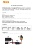
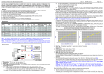
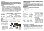
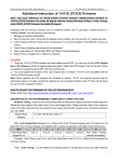
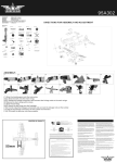
Thank you for purchasing this HOBBYWING product! Brushless power systems can be
very dangerous. Any improper use may cause personal injury and damage to the
ATTENTION
product and related devices. We strongly recommend reading through this user
manual before use. Because we have no control over the use, installation,
or maintenance of this product, no liability may be assumed for any damages or
USER MANUAL
losses resulting from the use of the product. We do not assume responsibility for any
Multi-Rotor
CAUTIONS
Brushless Electronic Speed Controller
XRotor Pro 40A • XRotor Pro 50A
losses caused by unauthorized modifications to our product.
01 Features
• Special core program for multi-rotor controllers greatly improves throttle response.
• DEO (Driving Efficiency Optimization) technology significantly improves throttle linearity and driving
efficiency.
• High intelligent and adaptive default settings like auto-adjusting timing meet almost all applications.
• The twisted-pair design of the throttle signal cable effectively reduces the crosstalk produced in
signal transmission and makes flight more stable.
• Compatible with various flight-control systems and supports a signal frequency of up to 621Hz.
(Note: all throttle signals over 500Hz are non-standard signals.)
• The high-light LED position on the XRotor Pro 50A ESC saves the trouble of mounting any extra
color light on multi-rotors.
• The DIP switches at the bottom of the XRotor Pro 50A ESC control the ESC ON/OFF status, color of
the LED light, ON/OFF of the DEO function and the motor rotation.
02 Specifications
Model
Con. Current
Peak Current (10s)
BEC
LiPo
Programmable Item
Weight
XRotor Pro 40A
40A
60A
NO
3-6S
DEO (ON/OFF)
50g (Version A)
45g (Version B)
66x21.8x11mm (Version A)
73.5x21.8x11mm (Version B)
Size
XRotor Pro 50A
50A
70A
NO
4-6S
DEO(ON/OFF) and etc.
(See instructions below)
56g
48 x 30 x 15.5mm
Note: Version A (Wire Leaded) connects brushless motor via output wires, while Version B (COB-Connector On Board) with gold-plated connectors already directly soldered onto the printed circuit board of the
ESC, so Version B hasn't output wires.
03 User Guide
Throttle Calibration & ESC Programming
Users need to calibrate the throttle range when they start to use a new XRotor brushless ESC or another transmitter.
1
Motor Wiring
Electronic Speed Controller
Plug the throttle signal cable
into the throttle (TH) channel
on your receiver.
Battery
Motor
Receiver
Plug the UBEC cable into
the special battery (BATT)
channel or any other
unoccupied channel on
UBEC
2
3
your receiver.
Throttle Range Calibration
We strongly recommend removing the
Turn on the
Ensure the transmitter and receiver
After the motor emits
transmitter, move
are well bound, and then connect
two short “Beep-beep”,
Throttle
the throttle stick
the ESC to the battery.
move the throttle stick
Calibration
to the top
(The receiver needs to be powered
to the bottom position
completed
position.
by an extra power supply.)
in 3 seconds.
propellers for your own safety and the
safety of those around you before
IMPORTANT
performing calibration and programming
functions with this system.
ESC Programming
A) XRotor Pro 40A
Turn on the
Connect the receiver to the
transmitter, and then
battery and ensure the transmitter
move the throttle stick
and receiver are well bound, and
to the top position.
then power on the ESC.
The motor will
beep different
tones circularly.
“Beep-beep-”Throttle Calibration; “Beep-beep-beep-”DEO ON;
Programming
“Beep-beep-beep-beep-” DEO OFF; If the throttle stick is moved to
is completed;
the bottom position 3 seconds after you hear the corresponding
and the ESC is
beeps, then the programming of that item is complete.
ready.
B) XRotor Pro 50A
Dip
Switch
Switch #1
(LED Status)
Switch #2
(LED Color)
Switch #3
(DEO Status)
Switch #4
(Motor Rotation)
On
Red
On
CW
Off
Green
Off
CCW
Option
With the DEO ON, for better throttle linearity, the ESC will automatically brake and quickly
reduce the motor speed when decreasing the throttle amount. This can remarkably improve
IMPORTANT
the movement of the multi-rotors and the stability of its flight direction. Moreover, this also
improves the driving efficiency of the ESC and reduces its operating temperature.
04 Normal Start-up Process and Protections
Turn on the transmitter and move the
throttle stick to the bottom position.
The motor will emit a long “beep —“1 second after the system is connected to the battery indicating the ESC is armed and the multi-rotor is ready to go.
• Start-up Protection: The ESC will shut down the motor if it fails to start the motor normally within 2 seconds by increasing the throttle value. In this case, you need to move the transmitter throttle stick back to
the bottom position and restart the motor. (Possible causes of this problem: poor connection/ disconnection between the ESC and motor wires, propellers are blocked, etc.)
• Over-load Protection: The ESC will cut off the power/output when the load suddenly increases to a very high value. Normal operation will not resume until the throttle stick is moved back to the neutral position.
The ESC will automatically attempt to restart when the motor and the ESC are out of sync.
• Throttle Signal Loss Protection: When the ESC detects loss of signal for over 0.25 second, it will cut off the output immediately to avoid an even greater loss which may be caused by the continuous high-speed
rotation of propellers or rotor blades. The ESC will resume the corresponding output after normal signals are received.
05 Trouble shooting
Trouble
Warning Tone
Possible Cause
Solution
The ESC was unable
to start the motor.
“Beep beep beep…”
(The motor beeps rapidly)
The throttle stick is not at the bottom position.
Move the throttle stick to the bottom position or recalibrate the throttle range.
The ESC was unable
to start the motor.
“Beep, beep, beep......”
(Time interval is 1 second)
No output signal from the throttle channel on
the receiver.
Check if the transmitter and receiver are well bound;
Check if the throttle wire has been properly plugged into the throttle channel on the receiver.
The ESC was unable
to start the motor.
“BB, BBB, BBBB”
(These tones are played circularly)
The“Normal / Reverse” direction of the throttle
channel on transmitter is incorrect.
Refer to the transmitter instructions and correctly set the "Normal/ Reverse" direction of
the throttle channel.