1
ON
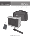
DELTA PA
User Manual
TABLE OF CONTENTS
SECTION 1:
4
Safety Instructions
5
6
7
8
9
10
System Components and Unpacking
Optional Components
Top Panel Wireless Receiver Controls
Top Panel Controls & Connections
Rear Panel Controls & Connections
Installing or Replacing Receiver Module
SECTION 2:
11
Set-up & Use
12
13
Step 1. Connecting the DELTA PA Receiver
to a Power Supply
Step 2A. Setting up one DELTA PA Receiver
Step 2B. Using More Than One DELTA PA
Receiver
Handheld Transmitter
Step 3. Channel Selection
Step 4. Battery Life & Battery Type
Step 5. Replacing Battery
Step 6. Recharging Batteries
Belt-pack
Step 7. Connecting & Placement
Step 8. Channel Selection
Step 9. Gain Adjust
Step 10. Battery Life Indicator & Type
Step 11. Replacing Batteries
Step 12. Recharging Batteries
Daily Use Instructions
Overview
14
15
16
17
18
19
20
21
22
23
24
SECTION 3:
25
Optional Accessories 26
27
Hand Held Microphone Transmitter
Belt-Pack Transmitter
Optional Speaker Stand and Bracket
Assembly
SECTION 4:
Troubleshooting
28
Troubleshooting Guide
SECTION 5:
Warranty &
Specifications
29
30
31
Warranty Statement
Safety Warnings
System Specifications
5. Warranty, Safety
& Specifications
4. Troubleshooting
3. Optional
Accessories
2. Setup & Use
1. Overview
IMPORTANT SAFETY INSTRUCTIONS
1.
Read these instructions.
2.
Keep these instructions.
3.
Heed all warnings.
4.
Follow all instructions.
5.
Do not use the apparatus near
water.
6.
Clean only with dry cloth.
7.
Do not block any ventilation
openings. Install in
accordance with the
manufacturer’s instructions.
8.
Do not install near any heat
sources such as radiators,
heat registers, stoves, or
other apparatus (including
amplifiers) that produce heat.
9.
Do not defeat the safety
purpose of the polarized
or grounding-type plug.
A polarized plug has two
blades with one wider than
the other. A grounding- type
plug has two blades and a
third grounding prong. The
wide blade or the third prong
is provided for your safety. If
the provided plug does not
fit into your outlet, consult an
electrician for replacement of
the obsolete outlet.
10. Protect the power cord
from being walked on or
pinched particularly at plugs,
convenience receptacles, and
the point where they exit from
the apparatus.
11. Only use attachments/
accessories specified by the
manufacturer.
4
12. Use only with a cart, stand,
tripod, bracket or table
specified by the manufacturer,
or sold with the apparatus.
When a cart is used, use
caution when moving the
cart/apparatus combination to
avoid injury from tip-over.
13. Unplug this apparatus during
lightning storms or when
unused for long periods of
time.
14. Refer all servicing to qualified
service personnel. Servicing is
required when the apparatus
has been damaged in any
way, such as power-supply
cord or plug is damaged,
liquid has been spilled or
objects have fallen into the
apparatus, the apparatus
has been exposed to rain or
moisture, does not operate
normally, or has been
dropped.
15. When the mains plug or
appliance coupler is used as
the disconnect device, it shall
remain readily operable.
16. Please keep the unit in a good
ventilation environment.
17. WARNING: To reduce the risk
of fire or electric shock, do not
expose this apparatus to rain or
moisture.
18. Apparatus shall not be
exposed to dripping or
splashing and no objects filled
with liquids, such as vases, shall
be placed on the apparatus.
SYSTEM COMPONENTS AND UNPACKING
The standard configuration of the DELTA PA will contain:
5. Warranty, Safety
& Specifications
1. Overview
2. Setup & Use
DELTA PA Public
Address System
and Power Supply
4. Troubleshooting
OVERVIEW
3. Optional
Accessories
SECTION 1:
DELTA PA Carry Case
5
Optional equipment which may be part of your DELTA PA system:
BP016 Transmitter and
Charger
831S Audio
-Technica 831
Lapel Mic
TK250S NoiseCancelling Headset
Microphone
HM016 Transmitter
ON
5. Warranty, Safety
& Specifications
4. Troubleshooting
3. Optional
Accessories
2. Setup & Use
1. Overview
OPTIONAL COMPONENTS
Individual Components
DPA016R
16 Channel UHF Receiver Module
HM016
16 Channel UHF Handheld Transmitter
MH7
Mic Holder for HM016 Handheld Transmitter
BP016
16 Channel UHF Belt-Pack Transmitter
BC016
Battery Charger for BP016 or HM016
831S
Audio-Technica 831 Lapel Mic
TK250S
Lightspeed Noise-cancelling Headset Mic
24V-2.5-A
AC Power Supply
NH1
AA NiMH Rechargeable Battery
SPDPA
Carry Bag for DELTA PA
AC-PWR-NA
AC North American Power Cable
Optional Accessories
6
GTC900
Guitar/aux In Cable for BP016
TWBRK
Speaker Stand Bracket
SS1
Tripod Speaker Stand
SPSS1
Carry Bag for Tripod Speaker Stand
H10
Wired Dynamic Handheld Mic
2
O/I
POWER/
RECVR 1
GREEN: ON
CHARGE
GREEN: FULL
RECVR 1
5
1
4
7
1. WIRELESS RECEIVER 1: One or
two wireless receiver modules are
located at the top panel.
2. CHANNEL DISPLAY: An LED
readout of the receiver module
indicates which channel you are
on.
3. CHANNEL CONTROL (1-16): The
left button increments the channel
number (1-16). Each touch of the
button moves the number up one
until it gets to sixteen. The right
button decrements the channel
number (16-1).
4. RF CHANNEL A/B INDICATOR:
The “A” LED lights up indicating
the A channel tuner is receiving
the strongest RF signal. The “B”
LED lights up indicating the “B”
channel tuner is receiving the
strongest RF signal.
5. Warranty, Safety
& Specifications
6
3. Optional
Accessories
RED: LOW BATT
5. TRANSMITTER LOW BATTERY
INDICATOR: This LED will light
to indicate the batteries in the
corresponding transmitter are
low.
2. Setup & Use
3
RECVR 2
POWER
1. Overview
RECVR 2
RED: CHARGING
4. Troubleshooting
TOP PANEL: WIRELESS RECEIVER CONTROLS
6.SCAN: Press this button to automatically select a channel that is
free from interference.
7. SQUELCH LEVEL ADJUSTMENT:
Covered with a plastic cap, the
squelch is adjusted at the factory
to provide the best signal level
and minimum noise. There is no
need to adjust the squelch level
in the field.
7
1
4. Troubleshooting
5. Warranty, Safety
& Specifications
TOP PANEL CONTROLS AND
CONNECTIONS
2
RECVR 2
3. Optional
Accessories
3
4
RECVR 2
O/I
POWER/
RECVR 1
5
POWER
RED: LOW BATT
GREEN: ON
CHARGE
2. Setup & Use
RED: CHARGING
GREEN: FULL
RECVR 1
6
1. Overview
7
1.BASS: Controls the level of low
frequency sound output for the
system.
2. TREBLE: Controls the level of
high frequency sound output for
the system.
Note: Reducing Feedback
The BASS and TREBLE controls
can be used to reduce feedback
(“squealing” or “howling”). If you
hear high-pitched squealing, lower
the treble setting. If you hear lowpitched howling, lower the bass
setting.
3. AUX IN/MIC IN: Controls the
volume of a wired microphone
plugged into MIC IN on the back
of the system and the volume of
an auxiliary piece of equipment
plugged into the AUX IN on the
8
back of the system.
4. WIRELESS RECVR 2: Controls the
volume of Wireless Microphone
2 if a second wireless receiver is
installed.
5. POWER/WIRELESS RECVR 1:
Turn this knob clockwise to power
up the system. Rotate to adjust the
volume of Wireless Microphone 1.
6. POWER LED:Green = Power On.
Red = Low Battery
7. CHARGING LED:Green = Full
Charge. Red = Charging
*Note: Internal Delta PA lithium
ion battery must be replaced
by licsensed Lightspeed service
center. Broken warning label will
void warranty.
4. Troubleshooting
1
5. Warranty, Safety
& Specifications
REAR PANEL CONTROLS AND CONNECTIONS
2
3
7
8
1. MIC IN: This ¼” jack provides
an input for a wired handheld
microphone.
2. AUX IN: This 3.5 mm jack
provides an input for audio from
an external device, such as a
CD player, MP3 player, TV/VCR,
computer, etc.
3. AUX OUT: This 3.5 mm jack
provides an adjustable-level
audio output that can be
connected to a recorder or
assistive listening device.
4. AUX OUT VOLUME: This knob
controls the level of the 3.5 mm
AUX OUT jack. Counterclockwise
represents a microphone level
signal, while fully clockwise
represents a line level signal.
5. AUX OUT: This ¼” jack provides
a line level output signal that
can be connected to a recorder,
assistive listening device, etc.
2. Setup & Use
6
1. Overview
5
3. Optional
Accessories
4
6. SPEAKER OUT (SWITCHED): This
¼” jack can be used to connect
to an external passive speaker.
[NOTE: connection to this jack will
mute the internal speaker of the
DELTA PA.]
*Note: Wiring to these terminals
should follow the Class 2 wiring
methods as outlined in the
National Electric Code.
7.FUSE: The fuse holder is
accessible using a flat-blade
screwdriver. Push in and rotate ¼
turn counterclockwise to remove.
[NOTE: replacement is a 3.15A SB
250V slow blow fuse.]
8. DC POWER: This jack provides
a connection for the DELTA PA
power supply.
9
5. Warranty, Safety
& Specifications
4. Troubleshooting
3. Optional
Accessories
NOTE: Make sure the DELTA PA is
turned off.
1. Remove the two screws securing
the module panel using a small
phillips head screwdriver.
2. Remove the module from the
enclosure by carefully inserting
the blade of a small, flat-blade
screwdriver under the face plate
edge and nudging it upward.
3. Grasp the edges of the module
with both hands and slide
it out.
4. Install the new module by
aligning it with the guide rails and
sliding all the way in to engage
the connector at the rear of the
module.
5. Replace the two screws.
1. Overview
2. Setup & Use
INSTALLING OR REPLACING A RECEIVER
MODULE
RECVR 2
RECVR 2
O/I
POWER/
RECVR 1
10
POWER
RED: LOW BATT
GREEN: ON
1. CONNECTING THE DELTA PA RECEIVER
TO A POWER SUPPLY
Note: When the DELTA PA is received,
plug in the power supply and let charge
overnight before using.
5. Warranty, Safety
& Specifications
SET-UP & USE
4. Troubleshooting
SECTION 2:
1.Locate the power supply.
2. Setup & Use
3. Optional
Accessories
2.Insert the DC connector into the
“POWER INPUT” connector on the
bottom of the DELTA PA and plug
the other end to an electrical
outlet.
RECVR 2
1. Overview
3.Turn the POWER/RCVR1 knob clockwise to turn the system
on.
4.The green LED light next to the
knob will illuminate to confirm the
system is powered up.
*Note: The DELTA PA can operate
on either DC power or battery
power.
RECVR 2
RECVR 2
RECVR 2
O/I
POWER/
RECVR 1
POWER
RED: LOW BATT
GREEN: ON
CHARGE
RED: CHARGING
O/I
POWER/
RECVR 1
POWER
RED: LOW BATT
GREEN: ON
CHARGE
GREEN: FULL
RED: CHARGING
GREEN: FULL
RECVR 1
11
RECVR 2
5. Warranty, Safety
& Specifications
2A. SETTING UP ONE DELTA PA RECEIVER
RECVR 2
4. Troubleshooting
RECVR 2
1. Turn the DELTA PA ON by rotating
the POWER/RCVR 1 knob
clockwise. The green LED will
light.
O/I
POWER/
RECVR 1
POWER
RECVR 2
RED: LOW BATT
O/I
POWER/
RECVR 1
GREEN: ON
CHARGE
GREEN: FULL
RED: CHARGING
Channel Selection: Receiver
RECVR 1
2. Clear Channel SCAN
(recommended):
A) Make sure the transmitter(s) is
OFF before pressing this button. When this button is pressed, the
receiver will cycle through all 16 channels and select a clear
frequency. (This process takes about 20 seconds.)
B) Once the receiver selects the
clear channel, you will need to select the same channel on the
corresponding transmitter
(handheld or belt-pack). See
pages 14 and 19 for instructions.
1. Overview
2. Setup & Use
GREEN: FULL
RECVR 1
Each Receiver has 16 user-selectable
channels to choose from. You can
either select a channel manually or
by pressing the SCAN button, which
will automatically select a clear
channel.
NOTE There are 3 different
groupings of 16 channels available
(620, 640, 660 MHz). Make sure the
receiver module frequency group
is the same frequency group as the
transmitter.
12
GREEN: ON
CHARGE
POWER
RED: LOW BATT
RED: CHARGING
ON
Channel 2
5. Warranty, Safety
& Specifications
2B. USING MORE THAN ONE DELTA PA
RECEIVER
A) Verify that RECVR 1
transmitter and receiver 1 are on and set to the same clear channel.
B) Make sure the transmitter for
RECVR 2 is turned off.
C) Press the SCAN button on the
RECVR 2.
D) After the RECVR 2 receiver
selects a clear channel, set the RECVR 2 transmitter
(handheld or belt-pack) to the
selected channel. See pages 14
and 19 for instructions.
3. Optional
Accessories
4. Troubleshooting
If you have a second DELTA PA:
A) Pressing the UP CHANNEL
button increases the channel
number by one.
B) Pressing the DOWN CHANNEL
button decreases the channel
number by one.
C) Once a frequency is selected,
you will need to select the same
channel on the corresponding
transmitter (handheld or beltpack). See pages 14 and 19 for
instructions.
1. Overview
2. Setup & Use
3. Manual Channel Selection:
ON
4. Set the Receiver 1 and Receiver 2
channels on the second DELTA PA
to be the same as the first DELTA
PA.
Channel 2
13
5. Warranty, Safety
& Specifications
4. Troubleshooting
3. CHANNEL SELECTION: HANDHELD
TRANSMITTER
Once a channel has been selected
on the receiver, you now need to
select that same channel on the
handheld transmitter. If you have a
belt-pack transmitter, go to page 19
for channel selection instructions.
ON
Same
Channel
1. Turn on the microphone by sliding
the power button on the barrel
forward. The LED will flash red.
1. Overview
ON
2. Setup & Use
2. Use a screwdriver to set the
channel switch to the current
channel shown on the RECVR
screen.
Transmitters and receivers are
available in 3 different frequency
groups (620, 640, 660 MHz). Verify
that the receiver frequency matches
the letter code on the silver sticker
in the battery compartment of the
transmitter.
Model Number: HM016
Serial Number
HM01614324024
FREQUENCY 660 MADE IN TAIWAN
Frequency
14
Battery Low Indicator
4. Troubleshooting
Battery low indicator is located
above the power switch. It glows red
when the battery charge is low and
recharging is necessary
5. Warranty, Safety
& Specifications
4. BATTERY LOW INDICATOR AND BATTERYTYPE ON HANDHELD MICROPHONE
3. Optional
Accessories
ON
Low Battery Light
1. Overview
The transmitter will operate with
either standard AA alkaline batteries
or nickel metal hydride (NiMH)
rechargeable batteries. Since these
types of batteries have different
characteristics, it is important not to
mix battery types. Use only AA NiMH
batteries when recharging.
2. Setup & Use
Battery Type
NOTE: Do not mix battery types.
WARNING: Do not use NiCad
batteries! They will not charge
properly and may cause damage to
the transmitter.
Lightspeed recommends Panasonic
or Energizer batteries. Duracell may
not work.
15
5. Warranty, Safety
& Specifications
5. REPLACING BATTERIES IN HANDHELD
MICROPHONE
1. Unscrew the end cap to reveal the
battery compartment.
2. Remove or replace the batteries
as shown. The microphone
requires two AA sized batteries
stacked end to end.
1. Overview
2. Setup & Use
3. Note the polarity in the battery
compartment.
16
IMPORTANT: Replace batteries
with the same type, (alkaline or
NiMH), that were installed in your
Handheld Microphone. Lightspeed
recommends Panasonic or Energizer
batteries. Duracell may not work
properly.
ON
4. Troubleshooting
Replacing the Batteries
4. Troubleshooting
Recharging the Batteries
(NiMH Rechargeable Batteries
ONLY):
ON
2. Setup & Use
1. Switch the transmitter power OFF.
3. Optional
Accessories
Make sure there are NiMH
rechargeable batteries in the
transmitter before plugging in
the charger. A full charge will be
attained in 8-10 hours. Fully charged
Lightspeed microphones will last
over 7 hours.
WARNING: Do not attempt to
charge alkaline batteries. They can
overheat and expand, creating a
significant hazard and damaging the
transmitter. (This is not covered by
warranty.)
5. Warranty, Safety
& Specifications
6. RECHARGING BATTERIES IN HANDHELD
MICROPHONE
3. Plug the other end of the charger
into any standard 110 VAC outlet.
4. The red LED on the charger will
light, indicating that charging is in
progress.
1. Overview
2. Insert the small DC plug into the
jack on the bottom of
the transmitter.
5. When the batteries are fully
charged, the LED on the charger
will glow green.
17
5. Warranty, Safety
& Specifications
7. CONNECTING AND PLACING BELT-PACK
TRANSMITTER
4. Troubleshooting
Connecting the Microphone
To connect the microphone, simply
insert the microphone connector
into the TA4F connector on top of
the transmitter. To remove, press
the black button on the microphone
connector and pull out.
1. Overview
2. Setup & Use
Microphone Options
Lightspeed offers two types of
microphones that can be used with
this system. The BP016 Transmitter
can be used with either a lapel
style microphone or a headset
microphone. Both plug into the top
of the transmitter as shown.
Lapel Microphone Placement
Simply connect the microphone cord
directly into the jack on top of the
transmitter and clip the microphone
to lapel or collar. For optimal sound,
position the microphone as close to
the mouth as possible.
Headset Microphone Placement
Simply connect the microphone
cord directly into the jack on top
of the transmitter and place the
headset around the back of the
head. For optimal sound, position
the microphone at the corner of the
mouth.
18
5. Warranty, Safety
& Specifications
8. CHANNEL SELECTION: BELT-PACK
TRANSMITTER
4. Troubleshooting
Channel Selection:
Once a channel has been selected
on the receiver, you now need to
select that same channel on the beltpack transmitter.
3. Optional
Accessories
1. Turn the transmitter power on by
sliding the PWR button to on. The
LED will flash red.
2. Open the battery compartment
door by depressing the latches on
each side of the transmitter.
1. Overview
2. Setup & Use
3. Use the screwdriver channel set
to switch to the current channel
shown on the receiver.
Transmitters and receivers are
available in 3 different frequency
groups (620, 640, 660 MHz). Verify
that the frequency group of the
receiver matches the letter code
on the silver sticker in the battery
compartment of the transmitter.
Model Number: BP016
Serial Number
BP01614324024
FREQUENCY 660 MADE IN TAIWAN
19
5. Warranty, Safety
& Specifications
9. GAIN ADJUST ON BELT-PACK
TRANSMITTER
4. Troubleshooting
Gain Adjust:
When changing microphones or
users, it may be necessary to adjust
the transmitter gain based on
differing microphones sensitivities
and voice levels.
To adjust the gain:
1. Open the battery compartment
door by depressing the latches on
each side of the transmitter.
1. Overview
2. Setup & Use
2. Turn the MT dial clockwise
to increase the gain and
counterclockwise to decrease the
gain.
NOTE: If you are using a high impedance
source, such as a guitar, it will be necessary to
adjust the GT dial. Using a high impedance
source requires a special cable. Contact
Lightspeed Customer Service at 800-7328999 for more information. Customers in
Canada should contact their local reseller.
20
5. Warranty, Safety
& Specifications
10. BATTERY LOW INDICATOR AND TYPE
ON BELT-PACK TRANSMITTER
The transmitter will operate with
either standard AA alkaline batteries
or nickel metal hydride (NiMH)
rechargeable batteries. Since these
types of batteries have different
characteristics, it is important not to
mix battery types. use only AA NiMH
batteries when recharging.
3. Optional
Accessories
Battery Type
2. Setup & Use
Battery low indicator is located next
to the power switch. It glows red
when the battery charge is low and
recharging is necessary.
4. Troubleshooting
Battery Low Indicator
WARNING: Do not use NiCad
batteries! They will not charge
properly and may cause damage to
the transmitter.
Lightspeed recommends Panasonic
or Energizer batteries. Duracell may
not work.
1. Overview
NOTE: Do not mix battery types.
21
5. Warranty, Safety
& Specifications
11. REPLACING BATTERIES IN BELT-PACK
TRANSMITTER
4. Troubleshooting
Replacing the Batteries:
1. Open the battery compartment
door by depressing the latches on
each side of the transmitter.
2. Remove or replace the batteries
and snap the door shut. The
belt-pack requires two AA sized
batteries.
1. Overview
2. Setup & Use
3. Note the polarity in the battery
compartment.
22
IMPORTANT: Replace batteries with
the same type, (alkaline or NiMH),
that were installed in your belt-pack
transmitter. Lightspeed recommends
Panasonic or Energizer batteries.
Duracell may not work properly.
WARNING: Do not attempt to
charge alkaline batteries. They can
overheat and expand, creating a
significant hazard and damaging the
transmitter. (This is not covered by
warranty.)
1. Switch the transmitter power off.
2. Insert the small DC plug into the
jack on the side of the transmitter.
5. Warranty, Safety
& Specifications
4. Troubleshooting
Make sure there are NiMH rechargeable batteries in the transmitter
before plugging in the charger. Fully
charged Lightspeed transmitters will
last over 7 hours. A full charge will be
attained in 8-10 hours.
3. Optional
Accessories
Recharging the Batteries
(NiMH Rechargeable Batteries
ONLY):
2. Setup & Use
12. RECHARGING BATTERIES IN BELT-PACK
TRANSMITTER
4. The red LED on the charger will
light, indicating that charging is in
progress.
5. When the batteries are fully
charged, the LED on the charger
will glow green.
1. Overview
3. Plug the other end of the charger
into any standard 110 VAC outlet.
23
5. Warranty, Safety
& Specifications
4. Troubleshooting
DAILY USE INSTRUCTIONS
1. Wireless Microphone Operation
RF Indicator Lights: When both
the system and the transmitter
are on and operating on the
same channel you will see a blue
glowing RF Indicator Light (either
A or B) on the receiver.
1. Overview
2. Setup & Use
2. VOLUME ADJUSTMENT: While
speaking into the microphone,
slowly turn the RECVR1 volume
knob (or RECVR2, depending
on which microphone you are
operating) clockwise until you
reach the desired level.
NOTE: Do not stand directly in front
of the DELTA PA speaker with the
microphone on. This will result in
feedback or ‘squealing.’ It is best to
stand behind or to the side of the
unit when setting volume level.
3. SQUELCH ADJUSTMENT:
Adjusting the squelch level
may be necessary to block out
potential interference in areas
that have very high radio traffic.
• Maximum squelch (full clockwise)
reduces reception range but also
reduces the potential for system
interference.
• Minimum squelch (full counterclockwise) increases reception
range, but also increases the
potential for system interference.
NOTE: In most cases it will not be
necessary to adjust the squelch
level. The system already has a clear
channel scanner to take care of most
interference problems.
4. TRANSMITTER LOW BATTERY
INDICATOR: This LED will light
to indicate the batteries in the
corresponding transmitter are
low and need to be replaced or
recharged.
24
RECVR 2
RECVR 2
RECVR 2
O/I
POWER/
RECVR 1
POWER
RED: LOW BATT
RECVR 2
GREEN: ON
CHARGE
RED: CHARGING
GREEN: FULL
O/I
POWER/
RECVR 1
POWER
RED: LOW BATT
GREEN: ON
CHARGE
RED: CHARGING
GREEN: FULL
RECVR 1
RECVR 1
OPTIONAL ACCESSORIES
5. Warranty, Safety
& Specifications
SECTION 3:
3. Optional
Accessories
4. Troubleshooting
HANDHELD MICROPHONE TRANSMITTER
3
4
1. RED LED: Lights up briefly when
power is switched on, flashes
continuously when audio is
muted.
1. Overview
2
2. Setup & Use
ON
1
2. POWER ON/OFF: Turns the
audio on and off. The red LED will
flash when power is turned on.
3. CHANNEL SWITCH: Screwdriver
adjust to set channel 1-16 to
match the channel setting of its
receiver.
4. BATTERY COMPARTMENT:
Bottom section of microphone
barrel unscrews to reveal battery
compartment.
25
5. Warranty, Safety
& Specifications
4. Troubleshooting
BELT-PACK TRANSMITTER
2
3
4
1
9
6
5
8
10
1. Overview
2. Setup & Use
7
1. ON/OFF BUTTON
2. RED LED: Lights up briefly when
power is switched on.
3. MICROPHONE JACK:
Microphone connects to
transmitter here.
4. ANTENNA
5. BATTERY CHARGER JACK:
Optional battery charger plugs in
here (for NiMH batteries only.)
6. DOOR LATCHES: Press both
latches to open the battery
compartment door.
7. GT (TRANSMITTER GAIN):
26
6
Provides adjustment for differing
voice levels and microphone
sensitivities.
8. MT (MICROPHONE GAIN):
Provides adjustment for differing
levels of high impedance sources,
i.e. guitars.
9. CHANNEL SET SWITCH:
Screwdriver adjust to set the
channel 1-16 to match its receiver
channel.
10. BATTERY COMPARTMENT
5. Warranty, Safety
& Specifications
4. Troubleshooting
OPTIONAL SPEAKER STAND AND BRACKET
ASSEMBLY
1. Position the legs of the speaker stand for
the appropriate height and width for the
application.
2. Extend the speaker stand shaft to desired
height.
3. Optional
Accessories
3. Insert safety pin at an appropriate level.
(see figure 1)
2. Setup & Use
figure 1
5. Place the Delta PA (DPA) amplifier upside
down on a table top.
6. Locate the 3 screw holes on the botom of
the amplifier.
1. Overview
7. Align the screw holes with the 3 holes on
the bracket as shown in figure 2.
figure 2
8. With the provided screws, attach the
bracket to the DPA.
9. Place the assembled DPA with bracket
onto the speaker stand as shown in figure
3.
10. Ensure the the top of the speaker stand is touching the top plate of the bracket..
figure 3
27
5. Warranty, Safety
& Specifications
4. Troubleshooting
3. Optional
Accessories
2. Setup & Use
1. Overview
SECTION 4:
TROUBLESHOOTING
COMMON PROBLEMS AND SOLUTIONS
Note:
No sound when someone speaks
into the wireless microphone:
1. DELTA PA power should be on.
The green LED should be lit. If it
does not light when the system
is switched on, make sure the AC
power supply is plugged in.
2. Microphone/transmitter power
should be on. If the low battery
indicator is on (red) the batteries
are most likely too weak. If the
batteries are rechargeable, plug
the microphone/transmitter into
the charger. If the batteries are
alkaline, replace them with new
alkaline batteries
WARNING: Do not attempt to
charge alkaline batteries. They can
overheat and expand, creating a
significant hazard and damaging
the warranty. (This is not covered by
warranty.).
3. The transmitter and receiver
should be set to the same
channel. The blue RF LED (A or B)
should be lit.
4. Verify that receiver and transmitter
are in the same frequency group.
Turn the DELTA PA off and then
on again. The letter code from
the frequency group will blink
on the receiver module. Open
the battery compartment on
the transmitter and be sure that
frequency group printed on the
sticker matches the frequency
group letter code that blinked
when the DELTA PA powered on.
If the letters are different, find a
microphone or belt-pack with
the same frequency group as
the receiver indicates when the
DELTA PA is turned on.
The wireless mic is experiencing
drop-out or interference:
1. The wireless frequency being
used may not be a clear channel.
Turn the transmitter off and press
the SCAN button on the receiver
to find a clear frequency. Then
select the same channel on the
transmitter.
2. Transmitter is out of range of
receiver. The transmitters have a
maximum range of about 300-350
feet in an open field environment.
This range can be dramatically
reduced indoors and outdoors
when large objects (such as a
wall) may be obstructing the path
directly between transmitter and
receiver. If so, position the two
closer together.
3. Batteries are very weak. Right
before the batteries are about
to die, the overall performance
of the system can be drastically
lessened. Check the battery status
of the transmitter.
Low Volume or Feedback:
1. Ensure microphone is positioned
appropriately.
2. Check volume level on the
amplifier. If the volume is too
high, feedback will occur. Adjust
accordingly.
If you review these instructions and still have questions, write down the
serial number and model number of your system and call Lightspeed
Technical Services at 800.732.8999, 5 a.m. – 5 p.m., PST. Customers in
Canada should call their local reseller.
28
1. The product must have been
purchased from an authorized
Lightspeed Technologies Dealer
or representative.
2. Lightspeed Technologies must
perform all warranty service.
Any service performed without
the authorization of Lightspeed
Technologies will void the entire
warranty.
3. This warranty does not cover any
product that has been subjected
to negligent use, connection
to improper power source,
misuse, or operated beyond its
manufactured specifications and
limits, or has not been reasonably
maintained.
4. Warranty shall not apply to
alkaline or NiMH batteries,
exterior finish, AC power cords,
bulbs, or any other failings due to
5. Warranty is void when equipment
is subjected to adverse
temperature, humidity, moisture,
or other conditions that are not
considered normal environmental
conditions.
6. This warranty excludes all
damages or defects caused
by shipping, transporting, or
inadequate packaging for
shipping.
7. Prepaid shipping label provided
by Lightspeed for warranty repair
within the U.S. Customers in
Canada should contact their local
reseller for service needs.
The warranty period for each system
and component type is listed below:
DELTA PA: Two (2) years from the
date of original purchase.
5. Warranty, Safety
& Specifications
4. Troubleshooting
normal wear.
3. Optional
Accessories
Lightspeed Classroom Audio
Systems are guaranteed against
malfunction due to defects in
materials and workmanship for a
period of TWO (2) YEARS, beginning
at the date of the purchase invoice. If
such malfunction occurs, the product
will be repaired or replaced (at
Lightspeed’s option) without charge
during the warranty period, subject
to the following conditions:
2. Setup & Use
WARRANTY, SAFETY &
SPECIFICATIONS
1. Overview
SECTION 5:
RF Wireless Transmitters and
Receivers: Two (2) years from the
date of purchase.
NiMH Batteries: One (1) year from
the date of purchase.
Microphones and Cases: One (1)
year from date of purchase.
Products will be replaced or repaired
at Lightspeed Technologies’ option
during the warranty period.
For warranty service, please contact Lightspeed Customer Service Department
to obtain return authorization approval and an RA number.
Our Service Department (800.732.8999, 5 a.m. – 5 p.m., PST)
will handle your repair/replacement needs. Customers in Canada should contact
their local reseller.
29
5. Warranty, Safety
& Specifications
SAFETY WARNINGS
4. Troubleshooting
LIGHTSPEED TECHNOLOGIES, INC. PH: 1.800.732.8999
Label Sp
WARNING
Label P/N: 3
WARNING: To Reduce The Risk Of Fire Or Electric Shock, Do Not
Expose This Apparatus To Rain Or Moisture
Units: Inches
Apparatus shall not be exposed to dripping or splashing and no
objects filled with liquids, such as vases, shall be placed on the
apparatus.
LABEL P/N: 334-0118-00
Date: 05/17
3. Optional
Accessories
Dederick
The lightning flash with arrowhead symbol within an equilateral triangle
is intended to alert the user to the presence of uninsulated “dangerous
voltage” within the product’s enclosure, that may be sufficient magnitude to
constitute a risk of electric shock.
2. Setup & Use
The exclamation point within an equilateral triangle is intended to alert the
user to the presence of important operating and maintenance (servicing)
instructions in the literature accompanying the appliance.
28.5mm / 1.122 inch
This product is listed to UL standards and requirements for electrical safety
by Underwriters Laboratories Inc.
FCC Caution
1. Overview
This device complies with Part 15 of the FCC Rules.
Operation is subject to the following two conditions:
(1) This device may
not cause
harmful
58mm
/ 2.2835
inchinterference, and
(2) This device must accept any interference received, including interference
that may cause undesired operation.
LIGHTSPEED TECHNO
To assure continued compliance, any changes or modifications not expressly
www.lightspeed-tek.co
approved by the party responsible for compliance could void the user’s
authority to operate this equipment. (Example - use only shielded interface
800.732.8999
cables when connecting to computer or peripheral devices).
DELTA PA & BP016 & HM016
Industry Canada Caution
LABEL SPECIFICATIONS
LABEL PART: 334-00118-00
REVISION: A
This device complies with Industry Canada licence-exempt RSS-123
DATE: 05/17/2012
standard.
MATERIAL:
Operation is subject to the following two conditions
: (1) this BLACK POLYESTER
device may not cause interference, and (2) this device must accept
ADHESIVE: UL APPROVED
any interference, including interference that may cause undesired
WIDTH: 58mm / 2.2835 inch
operation of the device.
BP016 & HM016
FCC Caution
HEIGHT: 28.5mm / 1.122 inch
THICKNESS: 2 MIL
COLORS: BLACK W/WHITE TEXT
ABS
THIS DEVICE COMPLIES WITH PART 74 OFSUBSTRATES:
THE FCC RULES.
ENVIRONMENT:
INDOOR/OUTDOOR USE
This equipment complies with FCC RF radiation
exposure limits set
forth for an uncontrolled environment.
APPLICATION: AFFIX LABEL BY SUPPLIER
SERIALIZED: NO
REGULATORY CONSIDERATIONS: UL APPROVED PROCESS FOR M
30
30 W at 2 Ω
Music Power [RMS]
40 W at 2 Ω
Amplifier Type
Analog Class AB
Frequency Response of amplifier
90 Hz - 18 kHz
Speaker System
Full-Range 6.5”/4 Ω
Microphone Input
¼ inch phone jack
Wireless Microphones
Up to two 16-Channel UHF True
Diversity
Line Input
3.5 mm
Line Output
3.5mm and ¼ inch
Tone Controls
Bass and Treble
Speaker Output
1 switched 2 Ω
Dimensions [H x W x D inches]
9.75 x 12.5 x 6.25
Weight
7.2 lbs./20.4 kg
5. Warranty, Safety
& Specifications
102 dB
System Power [RMS]
4. Troubleshooting
89 dB
Maximum SPL
3. Optional
Accessories
Nominal SPL [1W/1M]
2. Setup & Use
OVERALL SPECIFICATIONS
1. Overview
SYSTEM SPECIFICATIONS
31
5. Warranty, Safety
& Specifications
4. Troubleshooting
3. Optional
Accessories
2. Setup & Use
1. Overview
SYSTEM SPECIFICATIONS CONT’D
RECEIVER SPECIFICATIONS
Carrier System
Microprocessor Controlled
PLL Synthesized
Macro Frequency Range
620 to 679.75 MHz
[3 Macro-Groups]
Micro . Frequency Range
25 MHz each Macro-Group
Selectable Frequencies
16
Deviation
± 40 KHz Nominal
Sensitivity
-100 dBm at S/N ratio of >80 dB
Tone-code Frequency
32.768 KHz
Image Rejection
>85 dB
S/N Ration [Max]
>105 dB
TRANSMITTER SPECIFICATIONS
HM-016 Handheld Microphone
RF Power Output
50 mW Maximum
Spurious Emission
>60 dB below the carrier
Macro Frequency Range
620 MHz to 679.75 MHz
[3 Macro-Groups]
Selectable Frequencies
16
Tone-Code Frequency
32.768 KHz
Pre-Emphasis
50 µsec
Limiter Range
>30 dB or audio overload
Battery Type
2 AA
Battery Life [Alkaline]
Approx. 8 Hours
Weight w/o Batteries
4.2 oz/120 g
BP-016 Belt-pack
RF Power Output
50 mW Maximum
Spurious Emission
>60 dB below the carrier
Macro Frequency Range
620 MHz to 679.75 MHz
[3 Macro-Groups]
Selectable Frequencies
16
Tone-Code Frequency
32.768 KHz
Pre-Emphasis
50 µsec
Limiter Range
>30 dB or audio overload
Battery Type
2 AA
Battery Life [Alkaline]
Approx. 8 Hours
Microphone Connector
TA4F
Weight w/o Batteries
3 oz/85 g
CHANNEL FREQUENCY ASSIGNMENT
32
EE
620.000 - 639.750
HH
640.000 - 659.750
LL
660.000 - 679.750
LIGHTSPEED TECH NOL OG I E S
115 09 SW HERM A N R OA D / T UA LAT IN , OR 9 7 0 6 2
TO LL F REE: 800.73 2 .8 9 9 9 / P H ON E : 5 0 3 .6 8 4 .5 5 3 8 / FAX :
503 .684.3197
L I G HTSPEED-TEK.COM
MN0374US01-7