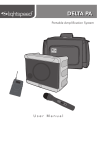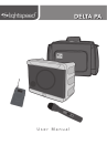
1
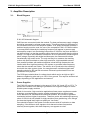
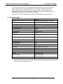
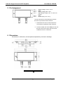
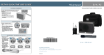
PZ235E User Manual E-831.05 Piezo Amplifier Module Release: 1.0.0 Date: 2012-03-06 This document describes the following product: E-831.05 Piezo Amplifier, Miniature OEM Module, 1 Channel, -30 to 130 V © Physik Instrumente (PI) GmbH & Co. KG Auf der Römerstr. 1 ⋅ 76228 Karlsruhe, Germany Tel. +49-721-4846-0 ⋅ Fax: +49-721-4846-1019 [email protected] ⋅ www.pi.ws E-831.05 Single-Channel LVPZT Amplifier Release 1.0.0 User Manual PZ235E [email protected] Page 2 E-831.05 Single-Channel LVPZT Amplifier User Manual PZ235E Table of Contents 0. Introduction ................................................................ 4 1. Safety ......................................................................... 4 1.1. Intended Use .............................................................................. 4 1.2. General Safety Instructions ........................................................ 5 1.2.1. Organizational Measures ............................................................ 5 1.2.2. Safety Measures during Installation ............................................ 5 1.2.3. Measures during Start-Up and Operation ................................... 7 1.2.4. Safety Measures during Maintenance ......................................... 7 2. Operating Principle ..................................................... 7 3. Amplifier Description................................................... 8 3.1. Block Diagram ............................................................................ 8 3.2. Power Supplies ........................................................................... 8 4. Technical Data ............................................................ 9 5. Pin Assignment ......................................................... 10 6. Dimensions ............................................................... 10 © Copyright 2012 by Physik Instrumente (PI) GmbH & Co. KG Release: 1.0.0 File:E-831_05_User_PZ235E100.doc, 182784 Bytes Release 1.0.0 [email protected] Page 3 E-831.05 Single-Channel LVPZT Amplifier User Manual PZ235E 0. Introduction E-831 is a compact single-channel amplifier for driving low-voltage piezoelectric translators (LVPZTs). It is an OEM module for PCB (printed circuit board) mounting. The E-831.05 amplifier is a highly compact but complete driver for LVPZTs having an average output power of about 2 W (without heat sink). Because the power consumption of a piezoelectric translator depends on the operating frequency and displacement amplitude, static or quasi-static operation can be controlled by such a low-cost, low-power amplifier. E-831s require two different voltages for operation. All required voltages can be supplied by either the E-841 or E-842 power supply modules, which run on single DC sources. See the corresponding user manuals for more information. Product Features: Designed for PCB mounting Low cost Small footprint Low noise Easy-to-use Internal or external clocking Low profile High stability Fully stable for capacitive loads Fully overcurrent, short-circuit and temperature protected For small loads, operates without heat sink Powers up and down without voltage spikes 1. Safety 1.1. Intended Use The E-831.05 is a laboratory device as defined by DIN EN 61010-1. It is intended to be used in interior spaces and in an environment which is free of dirt, oil and lubricants. The E-831.05 must be installed in a suitable case before start-up. The E-831.05 is designed and intended for driving capacitive loads (e. g. piezo ceramic actuators). The E-831.05 must not be used for purposes other than those named in this user manual. In particular, the E-831.05 must not be used to drive ohmic or inductive loads. The E-831.05 can be used for static as well as dynamic applications. The E-831.05 is intended for open-loop control. Release 1.0.0 [email protected] Page 4 E-831.05 Single-Channel LVPZT Amplifier 1.2. User Manual PZ235E General Safety Instructions The E-831.05 is built according to state-of-the-art technology and recognized safety standards. Improper use can result in personal injury and/or damage to the E-831.05. Only use the E-831.05 for its intended purpose, and only use it if it is in a good working order. Read the user manual. Immediately eliminate any faults and malfunctions that are likely to affect safety. The operator is responsible for the correct installation and operation of the E831.05. 1.2.1. Organizational Measures 1.2.1..1 User Manual Always keep this user manual next to the E-831.05. If the user manual is lost or damaged, contact our customer service department. Add all information given by the manufacturer to the user manual, for example supplements or Technical Notes. Only use the device on the basis of the complete user manual. Missing information due to an incomplete user manual can lead to slight injury as well as property damage. Only install and operate the E-831.05 after having read and understood this user manual. 1.2.1..2 Personnel Qualification The E-831.05 may only be started up, operated, maintained and cleaned by authorized and qualified staff. 1.2.2. Safety Measures during Installation Install the E-831.05 near the power source so that it can be quickly and easily disconnected from the power source. Release 1.0.0 [email protected] Page 5 E-831.05 Single-Channel LVPZT Amplifier User Manual PZ235E If the E-831.05 is operated without a case, live parts will be accessible. Touching the live parts can result in serious injury or death. Electrical, magnetic and electromagnetic fields emitted by live parts can disturb the E-831.05 and/or the environment. Before start-up, install the E-831.05 in a shielded case that securely encloses all live parts. Make sure that the E-831.05 fulfills all the requirements of electromagnetic compatibility after being installed in the case. If a protective earth conductor is not or not properly connected, dangerous touch voltages can occur and there is a risk of electric shock. In the case of malfunction or failure of the system, touching the E-831.05 can result in slight injuries. Install the E-831.05 in a metal case that is connected to a protective earth conductor. Connect at least one of the GND pins of the E-831.05 to the case in which the E-831.05 is installed so that it is conductive. Make sure that the contact resistance is < 0.1 ohm at 25 A at all connection points relevant for the function of the protective earth conductor. If the protective earth conductor has to be temporarily removed (e.g. for modifications), reconnect the protective earth conductor before starting the E831.05 up again. The E-831.05 contains electrostatically sensitive equipment (ESD) and can be damaged if handled improperly. Avoid touching assemblies, pins and PCB traces. Before you touch the E-831.05, discharge yourself of any electric charges: − Wear an antistatic wrist strap or − Before touching an electronic component, briefly touch a conducting, grounded object. Only handle and store the E-831.05 in environments that dissipate existing static charges to earth in a controlled way and prevent electrostatic charges (ESD workplace or electrostatically protected area, in short EPA). Release 1.0.0 [email protected] Page 6 E-831.05 Single-Channel LVPZT Amplifier User Manual PZ235E 1.2.3. Measures during Start-Up and Operation If the E-831.05 is operated without a case, live parts will be accessible. Touching the live parts can result in serious injury or death. Electrical, magnetic and electromagnetic fields emitted by live parts can disturb the E-831.05 and/or the environment. Only operate the E-831.05 when it is installed in a shielded case that securely encloses all live parts and fulfills the requirements of electromagnetic compatibility. If a protective earth conductor is not or not properly connected, dangerous touch voltages can occur and there is a risk of electric shock. In the case of malfunction or failure of the system, touching the E-831.05 can result in slight injuries. Only operate the E-831.05 when a protective earth conductor is connected. Supply voltages that are too high or incorrectly connected can cause damage to the module. No limiting components are included. Do not exceed the supply voltage range (see p. 9) for which the E-831.05 is specified. Only operate the E-831.05 when the supply voltages are properly connected (for pin assignment, see p. 10). 1.2.4. Safety Measures during Maintenance The E-831.05 is maintenance-free. 2. Operating Principle Low-voltage PZTs can be driven with an extended voltage range of -30 V to +130 V. This range can be fully covered by the E-831. Piezo actuators are, to a first approximation, capacitors, which means the current flow depends on the frequency of operation or, more generally, the slew rate of a changing signal. In static operation, almost no power will be needed. E-831 amplifier modules can be used for applications requiring a signal-amplifier. The operation mode is that of a power amplifier with a fixed gain of 10. This means for an output voltage swing of -20 to +120 V at the HV-OUT pin, the control voltage at the CONTROL IN pin has to run from -2 to +12 V. The output is fully compensated for capacitive loads from 0 μF to 10 µF, which is the typical range of PI's low-voltage piezo actuators. E-831.05 small-signal bandwidth is about 15 kHz. The output is subjected to 2 current limits: for short periods it can provide up to 250 mA, but the long-term limit is 100 mA. This allows to load a capacitor relatively fast but still makes the output circuit short-circuit-safe without time limitation. In the case temperature exceeds 75°C (can be reached after a few minutes with maximum current), an internal sensor will shut down the output stage until the temperature is below 65°C. Release 1.0.0 [email protected] Page 7 E-831.05 Single-Channel LVPZT Amplifier User Manual PZ235E 3. Amplifier Description 3.1. Block Diagram E-831.05 Schematic diagram GND lines are connected inside the module. For best performance supply voltages should be generated by a linear power supply. This allows taking full advantage of the excellent noise level of the amplifier module. If for space and power reasons a switched supply must be used, the one of the companion E-841 or E-842 modules is recommended. Naturally the switching frequency will appear in power supply and amplifier output, but at switching frequencies of 100 kHz, the piezo actuator is not able to follow, so that the resulting motion has much less noise than the driving voltage. This has to be considered if resolution is to be specified by measuring the piezo voltage. Especially with digital oscilloscopes, the measurement shows unrealistically high noise levels. The only real way is to measure the resulting motion with optical methods or other high-resolution, high bandwidth sensors. One possible problem with switched supplies is that the high frequencies can interact with other high frequencies in the system to generate lower-frequency noise that the actuator can follow. The solution is to synchronize the switching clock with the other system clocks, for example sensor excitation signals and sampling clocks for AD and DA converters. External synchronization lines are provided for this purpose. The PCB layout should allow for voltage levels which can be as high as 180 V between neighboring pins and up to 140 V from ground. This requires sufficient air gaps, depending on the application environment. 3.2. Power Supplies The E-831.05 requires voltages in the range of -28 to -38 V and 127 to 137 V. To prevent the customer from having to generate such untypical voltages PI offers suitable power supply modules. While for low-noise / high-resolution applications linear power supplies are easier to design, most applications require smaller packages and low power losses. Piezo actuators, for mechanical and electrical reasons, are not able to generate mechanical noise at higher frequencies. Therefore power with switching frequency noise of 100 kHz is still suitable for high-resolution piezo positioning, even though the electrical signal itself might not qualify as “low-noise.” Care should be taken if the system includes sensors with AC excitation or data sampling. If the different clock signals or their harmonics have frequencies relatively close together, their beat frequency can appear as noise. Release 1.0.0 [email protected] Page 8 E-831.05 Single-Channel LVPZT Amplifier User Manual PZ235E The solution PI provides is to make possible synchronization of the power supply with an external clock. In complex systems, or when the master clock is much higher and the various frequencies are made by dividers, more sophisticated synchronization circuits are sometimes necessary. This is because the phase shift of different dividers can affect precision and stability. See the E-841 / E-842 User Manual for detailed information on these modules. 4. Technical Data E-831.05 Function Miniature piezo amplifier module, 1 channel Amplifier Control input voltage -2 to 12 V Output voltage* -30 to 130 V Peak current (<8 ms) 250 mA Average current (up to 1 minute without cooling) 100 mA Current limitation Short-circuit-proof Voltage gain 10±0.1 Amplifier bandwidth, small signal 15 kHz (open) (-3 dB, 5 Vpp) Ripple, noise, 0 to 100 kHz <0.15 mVrms <1 mVpp Capacitive base load (internal) 10 nF Output impedance 5Ω Input impedance 1 MΩ Miscellaneous Contacting Soldering pins, Ø 0.7 mm, 9 mm Operating temperature range 5 to 50°C Overtemp protection Deactivation at a case temperature of 75°C Dimensions 60 × 28 × 6 mm Material Metal shielded case Operating voltage 127 to 137 V / 6 mA -28 to -38 V / 6 mA Dynamic current consumption Depending on load, amplitude and slew rate * Depending on the power supply. Full voltage swing with E-841.55. With E-841.05 and E-842.05 max. -20 to 120 V for up to three amplifier modules. Release 1.0.0 [email protected] Page 9 E-831.05 Single-Channel LVPZT Amplifier User Manual PZ235E 5. Pin Assignment Pin 1 Pin 2 Pin 3 Pin 4 Pin 5 Pin 6 Supply Voltage +127 to +137 V GND* Supply Voltage -28 to -38 V High Voltage Output (-30 V to +130 V for LVPZT) GND* Control Input (-2 to +12 V) *Connect at least one of the GND pins of the E831.05 to as protective earth conductor: 1. Install the E-831.05 in a metal case that is connected to a protective earth conductor. 2. Connect at least one of the GND pins of the E831.05 to the case in which the E-831.05 is installed so that it is conductive. 6. Dimensions Dimensions in millimeters, decimal places separated by commas in drawings Release 1.0.0 [email protected] Page 10