1
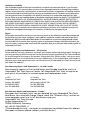
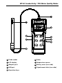
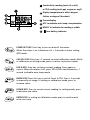
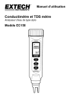
WT-60 Conductivity / TDS Water Quality Meter Users Manual • • • • Mode d’emploi Bedienungshandbuch Manual d’Uso Manual de uso WT-60 Users Manual September 2009, Rev.1 ©2009 Amprobe Test Tools. All rights reserved. Printed in China English Conductivity / TDS Water Quality Meter Limitation of Liability Your Amprobe product will be free from defects in material and workmanship for 1 year from the date of purchase. This warranty does not cover fuses, disposable batteries or damage from accident, neglect, misuse, alteration, contamination, or abnormal conditions of operation or handling. Resellers are not authorized to extend any other warranty on Amprobe’s behalf. To obtain service during the warranty period, return the product with proof of purchase to an authorized Amprobe Test Tools Service Center or to an Amprobe dealer or distributor. See Repair Section for details. THIS WARRANTY IS YOUR ONLY REMEDY. ALL OTHER WARRANTIES - WHETHER EXPRESS, IMPLIED OR STAUTORY INCLUDING IMPLIED WARRANTIES OF FITNESS FOR A PARTICULAR PURPOSE OR MERCHANTABILITY, ARE HEREBY DISCLAIMED. MANUFACTURER SHALL NOT BE LIABLE FOR ANY SPECIAL, INDIRECT, INCIDENTAL OR CONSEQUENTIAL DAMAGES OR LOSSES, ARISING FROM ANY CAUSE OR THEORY. Since some states or countries do not allow the exclusion or limitation of an implied warranty or of incidental or consequential damages, this limitation of liability may not apply to you. Repair All test tools returned for warranty or non-warranty repair or for calibration should be accompanied by the following: your name, company’s name, address, telephone number, and proof of purchase. Additionally, please include a brief description of the problem or the service requested and include the test leads with the meter. Non-warranty repair or replacement charges should be remitted in the form of a check, a money order, credit card with expiration date, or a purchase order made payable to Amprobe® Test Tools. In-Warranty Repairs and Replacement – All Countries Please read the warranty statement and check your battery before requesting repair. During the warranty period any defective test tool can be returned to your Amprobe® Test Tools distributor for an exchange for the same or like product. Please check the “Where to Buy” section on www. amprobe.com for a list of distributors near you. Additionally, in the United States and Canada InWarranty repair and replacement units can also be sent to a Amprobe® Test Tools Service Center (see below for address). Non-Warranty Repairs and Replacement – US and Canada Non-warranty repairs in the United States and Canada should be sent to a Amprobe® Test Tools Service Center. Call Amprobe® Test Tools or inquire at your point of purchase for current repair and replacement rates. In USA Amprobe Test Tools Everett, WA 98203 Tel: 888-993-5853 Fax: 425-446-6390 In Canada Amprobe Test Tools Mississauga, ON L4Z 1X9 Tel: 905-890-7600 Fax: 905-890-6866 Non-Warranty Repairs and Replacement – Europe European non-warranty units can be replaced by your Amprobe® Test Tools distributor for a nominal charge. Please check the “Where to Buy” section on www.amprobe.com for a list of distributors near you. Amprobe® Test Tools Europe In den Engematten 14 79286 Glottertal, Germany tel: +49 (0) 7684 8009 - 0 *(Correspondence only – no repair or replacement available from this address. European customers please contact your distributor.) WT-60 Conductivity / TDS Water Quality Meter 1 Probe socket 6 Probe 2 LCD display 7 Temperature sensor 3 Adaptor port 8 Battery cover (rear side) 4 USB port 9 Tripod mount hole (rear side) 5 Operation keys 1 Conductivity reading (unit: uS or mS ) or TDS reading (unit: ppt or ppm or mg/l) 2 Display temperature in either degree Celsius or degree Fahrenheit 3 Freeze display 4 ATC to indicate auto temp. compensation 5 READY to indicate the reading is stable 6 low battery indicator POWR/SET KEY: Press key to turn on and off the meter. When the meter is on, hold down for > 2 seconds to enter setting (SET)mode. CAL/ESC KEY: Press key > 2 seconds to enter calibration mode. While in calibration or setting mode, press to return to previous mode. HOLD KEY: Press key to freeze current reading. Press again to unlock. When the meter is off, press SET+HOLD simultaneously > 1 second to disable auto-sleep mode. MODE KEY: Press this key to switch Cond. & TDS. Press > 2 seconds to manually set range. In setting or calibration mode, press to increase value. DOWN KEY: Press to record current reading. In setting mode, press to decrease the value. ENTER KEY: In setting or calibration mode, press to confirm and enter next step. WT-60 Conductivity / TDS Water Quality Meter CONTENTS SYMBOLS..................................................................................................................2 UNPACKING AND INSPECTION................................................................................2 INTRODUCTION........................................................................................................2 Features................................................................................................................3 OPERATION . ............................................................................................................3 Auto Power Off ...................................................................................................4 Set Up...................................................................................................................5 Calibration Mode.................................................................................................8 Conductivity calibration ..............................................................................8 TDS calibration .............................................................................................9 SPECIFICATION........................................................................................................10 MAINTENANCE AND REPAIR.................................................................................11 Battery Replacement ........................................................................................11 USB PC INTERFACE CAPABILITIES..........................................................................12 TROUBLESHOOTING...............................................................................................12 APPENDIX A............................................................................................................14 APPENDIX B............................................................................................................15 APPENDIX C............................................................................................................15 1 SYMBOL � Caution ! Refer to the explanation in this Manual � Conforms to relevant Australian standards � Complies with European Directives = Do not dispose of this product as unsorted municipal waste. �Warning and precaution • Do not make the air bubble adhere on the electrode. That may cause inaccurate reading. • Do not operate the meter in flammable liquid. UnpAcking and Inspection Your Shipping carton should include: 1 WT-60 Conductivity / TDS Water Quality Meter 1 Probe 4 AAA batteries 1 User's Manual If any of the items are damaged or missing, return the complete packag to the place of purchase for an exchange. INTRODUCTION Congratulations on your purchase of WT-60 Conductivity/TDS water quality meter. Conductivity measurements are used extensively in many industries. For example, conductivity measurements are used to monitor quality in public water supplies, in hospitals, in boiler water and industries which depend on water quality such as brewing. WT-60 is a convenient instrument to measure water conductivity, TDS and temperature. 2 Features • Dual display with ATC (°C / °F switchable) • Data hold to freeze display • Selectable conductivity to TDS conversion factor • USB download capabilities • Low battery indicator. • Auto power off • Maximum 5 calibration points OPERATION Conductivity Measurement 1. Select range: Meter is defaulted at "auto-ranging" which determines and selects the range and gives the greatest resolution and accuracy. Alternatively, you can manually select by pressing MODE >2 seconds. 5 ranges for selection and “rAn” (auto ranging). It cycles from 1 to 5 and get back to auto. (Fig. 1) Fig. 1 2. Automatic Temperature Compensation: The meter is defaulted as ATC on. To disable ATC, refer to programming setting P1.3 and P3.3 for manual temp. compensation. 3. ASetting correct temperature coefficient: Factory default is 2.1% per C (temperature coefficient) and this provides good results for most applications. Refer P3.1 if a different value is needed. 4. Select normalization temperature: Factory default is 25 °C. Refer P3.2 if a different value is needed. 3 5. Rinse the probe with deionized or distilled water to remove any impurity adhering to electrode body. If the electrode isn't used for a long time, please soak probe for more than 8 hours to clear up the lazy effect of the probe. 6. Dip the probe into the sample. Make sure no air bubbles are tapped on the slot of the probe. To remove air bubbles, stir the probe mildly and make sure the electrode tip is submerged. 7. Stir the probe gently to create a homogenous sample. 8. Take readings. When the reading is stable, "READY" will display on the left-middle LCD. TDS Measurement 1. Set a correct TDS conversion factor. Factory default is 0.50. Refer P1.1 if a different value is needed. See Appendix A & B for more information. 2. Select range & ATC/manual TC per your application. 3. Take readings. Press "MODE" to switch to TDS mode and get the reading. Auto power off This meter will shut off automatically 20 minutes of inactivity. To disable the auto power off, pressing "SET" + "HOLD" keys simultaneously while turning on the meter until a "n" appeared on the screen and then release keys to return to normal mode. (Fig.2) Fig. 2 4 Setup The advanced setup mode lets you customize your meter. 4 types parameter are available. P1.0: Meter configuration: (CoF) P1.1:TDS factor(tdS) P1.2: READY indicator:(rdy) P1.3: ATC or Manual TC: (Atc) P2.0: Unit :(Unt) P2.1 select OC or OF:(t) P2.2 select ppm or mg/L: (tdS) P3.0: temperature parameters: (t) P3.1: Temperature coefficient:(tCo) P3.2: Normalization temperature:(nor) P4.0: View calibration data (CAL) P5.0: Electrode data:(ELE) P7.0: Reset to factory default setting(rSt) P1.0: Meter configuration: (CoF) P1.1: TDS factor (tdS): The dissolved salts increases conductivity but the effect varies from sal to salt and is roughly linear in a given range for a given salt. The TDS conversion factor is used to convert conductivity into TDS. In P1.0, press ENTER to enter P1.1. Press again to see TDS factor flashes on LCD (Fig.3). Press UP/DOWN to change the value from 0.40 to 1.00. The default value is 0.50. Press ENTER to confirm and enter P1.2. Fig. 3 5 P1.2: READY indicator: (rdy) Meter is defaulted as "ON". Icon displays when measurement gets stable. Users can turn it off for faster response. Press UP /DOWN to switch "on" and "off". Press ENTER to confirm and enter P1.3. P1.3: ATC or Manual TC: (Atc) Meter is defaulted as ATC on. Press UP/DOWN to switch on and off. Press ENTER to confirm and return to P1.0. P2.0: Unit : (Unt) P2.1: Select °C or °F:(t) Select P2.0 and press ENTER to P2.1. Default unit oC is blinking on LCD. Press UP/DOWN to switch oC and oF. Press ENTER to confirm and enter P2.2. P2.2: Select ppm or mg/L: (tdS) The default TDS unit “ppm” blinks on LCD. Press UP/ DOWN to switch between ppm and mg/l, Press ENTER to confirm and return to P2.0. P3.0: temperature parameters: (t) P3.1: Temperature coefficient: (tCo) The temp. coefficient (expressed in percent per °C) is the changed ratio of conductivity per degree of temp..The adjustable range is 0.0 per °C to 10.00 % per °C. The default is 2.10% per °C. 0.0% has no effect on temp. So the displayed value is the same as actual temperature. Select P3.0 and press ENTER to enter P3.1.Press ENTER again and Temperature Coefficient flashes on LCD (Fig.4). Press UP/DOWN to change the value from 0.0 to 10.0. Press ENTER to confirm and enter P3.2. Fig. 4 6 P3.2: Normalization temperature: (nor) The meter will normalize its cond. measurement to a standard temp. which you preset. The adjustable range is 15 to 30 °C (59 to 86 °F). Meter default is 25 °C (77°F). When in P3.2, press ENTER again and the default normalization temperature flashes on LCD. Press UP/DOWN to change the value from 15.0 to 30.0 °C. Press ENTER to confirm and enter P3.3. For more information of temperature effect on measurement, refer to Appendix C. P3.3: Manual temp. Compensation: (Int) When ATC is disabled, you can manually enter the temp.value of solution. Any temperature between 0 and 50 °C (32 to 122 °F) is selectable. Meter default is 25 °C (77°F). When in P3.3, press ENTER again and the default manual temperature 25.0°C blinks on LCD. Press UP/DOWN to change the value. Press ENTER to confirm and return to P3.0. P4.0: V iew calibration data (CAL) Recall previous calibration data and help to know when is needed to re-calibrate. It’s for "Review" purpose only In P4.0, press ENTER repeatedly to view P4.1to P4.5, and it returns P4.0 after 4.5 P4.1 is calibration data for range 1, P4.2 is for range 2, .....P4.5 is for range 5. If no previous calibration data at particular range, the display will show “ - - -“. P5.0: Electrode data: (ELE) To check the probe cell constant value for diagnostic purposes. The cell constant is adjusted according to your calibration. In P5.0, press ENTER repeatedly to view P5.1 to P5.5 , and it returns to P5.0 after P5.5. P5.1 is the cell constant value for range 1. P5.2 is for range 2, .... P5.5 is for range 5. P7.0: Reset to factory default setting (rSt) P7.1: Meter reset (rSt) Reset all parameters to factory default. This function will clear all calibration data and all setup value you’ve done. In P7.0, press ENTER to enter P7.1. Press UP/DOWN to select "n"-NO or "y"-YES. Press ENTER to confirm and return to P7.0. To completely recalibrate a meter or using a replacement probe, it is suggested to clear all calibration data in memory. 7 Calibration Mode Selecting a calibration standard For best results, select a conductivity or TDS standard near the sample value you are measuring. Alternatively, use a calibration solution value which is approximate 2/3 of the full scale of the measurement range you plan to use. For example, in the 0 to 1999 uS range, use 1413 uS solution for calibration. DO NOT reuse the calibration solution. Contaminants in the solution will affect the calibration and the accuracy. When to do the calibration? Calibration is necessary and should be done regularly. If measure the mid-ranges, calibrate the meter at least once a month. Soak the probe for 15 mins before calibration or measurement can saturate the probe surface and minimize drift. If measure the extreme temperatures or special concentration (<100uS or >2mS), calibrate the meter at least once a week to get specified accuracy. Conductivity calibration 1. Dip the probe into demineralized or distilled water for about 30 minutes to rinse the probe. 2. Select the conductivity standard for calibration. 3. Pour enough solution into two separate clean containers. 4. Power on the meter. Select the mode as conductivity measurement mode. 5. Rinse the probe into one of above containers. Gently stir the probe. 6. Dip the rinsed probe into the second container. Tap probe on the bottom of container to remove air bubbles. Wait about 15 mins to make the probe stabilize to the solution temperature. 7. Press CAL > 2 seconds to begin calibration. The conductivity value of solution will blink on LCD (Fig.5). Fig. 5 8 8. Press UP/DOWN to change the value in order to match the value to the standard solution (solution must be referred to normalization temp. 20°C if P3.2 has re-adjusted as 20°C). You can adjust the conductivity reading for +20%. However, if the measured value and standard value differs by more than 20%, it is suggested to clean probe or replace meter. 9. When calibration is stable, ”READY” will display on LCD, press SET to confirm and return to conductivity measurement mode. If “READY” doesn’t show, check if the calibration solution is stable enough and whether the step 8 input value is correct or not. 10. Repeat 1~9 for other ranges if needed. 11. To exit conductivity calibration mode without confirming, press ” ESC “ in step 9. TDS calibration Option1: Using TDS standards 1. Dip the probe into demineralized or distilled water for about 30 minutes to rinse the probe. 2. Select the TDS standard for calibration. The factory default setting of the TDS conversion factor is 0.50. You can improve the calibration accuracy by setting the TDS factor before starting the calibration. Please refer Appendix A for more information of TDS conversion factor. 3. Pour enough solution into two separate & clean containers. 4. Turn on the meter. Press “MODE“ to select TDS mode. 5. Rinse the probe into one of the containers. Gently stir the probe. 6. Dip the rinsed probe into the second container. Tap the probe on the bottom of container to remove air bubbles. Let the probe stabilize to the solution temperature. 7. Press CAL >2 seconds to begin the calibration. The TDS value will blink on the LCD (Fig.6). Fig. 6 9 8. Press the UP/DOWN to adjust the value to match the value to the standard solution. 9. When calibration is stable, ”READY” will display on LCD, press SET to confirm and return to TDS measurement mode 10. Repeat 1~9 for other ranges if needed. Option2: Using Conversion Factors TDS values are related to conductivity. You can calibrate the meter by using conductivity standards as described above and then program the meter with a given conversion factor. Please refer to setting P1.1. SPECIFICATION Range Cond. (uS/cm): 0~19.99, 0~199.9, 0~1999 (mS/cm): 0~19.99, 0~199.9 TDS (ppm): 0~19.99, 0~199.9, 0~1999 (ppt): 0~19.99, 0~199.9 Resolution: 0.05% Full Scale Accuracy: 1% Full Scale±1digit TDS factor: 0.40~1.00 Calibration Standard: (0.3~1) * Full Scale Range ATC: 0~80°C / 32~176°F Temperature Range: 0~93°C / 32~199°F Temperature Res.: 0.1°C/°F Temperature Accuracy: ±0.6°C(<50°C), +1°C (>50°C) Temp. Coefficient: 0.0~10.0% per degree C Normalization Tempe.: 15.0~30.0°C Cell Constant: 1.0 Operation temp.: 0~50°C / 32~122°F Power Requirements: 4pcs1.5V (Type: AAA) � EMC: Conforms to EN61326-1. This product complies with requirements of the following European Community Directives: 89/ 336/ EEC (Electromagnetic Compatibility) and 73/ 23/EEC (Low Voltage) as amended by 93/ 68/ EEC (CE Marking). However, electricalnoise or intense electromagnetic fields in the vicinity of the equipment maydisturb the measurement circuit. Measuring instruments will also respond tounwanted signals that may be present within the measurement circuit. Usersshould exercise care and take appropriate precautions to avoid misleading results when making measurements in the presence of electronic interference. 10 MAINTENANCE AND REPAIR If there appears to be a malfunction during the operation of the meter, the following steps should be performed in order to isolate the cause of the problem. 1. Check the battery. Replace the battery immediately when the symbol “ ” appears on the LCD. 2. Review the operating instructions for possible mistakes in operating procedure. Except for the replacement of the battery, repair of the meter should be performed only by a Factory Authorized Service Center or by other qualified instrument service personnel. The front panel and case can be cleaned with a mild solution of detergent and water. Apply sparingly with a soft cloth and allow to dry completely before using. Do not use aromatic hydrocarbons, Gasoline or chlorinated solvents for cleaning. Make sure the electrode is clean! Between measurements,rinse the electrode with deionised water. If the electrode has been exposed to a solvent immiscible with water, clean it with a solvent miscible with water e.g. ethanol or acetone and rinse carefully with water.Store the electrode carefully! Before storing, rinse it carefully in deionized water and store DRY. Battery Replacement 1. Turn off the meter and open the battery cover. 2. Replace the old batteries with four new AAA batteries. 11 USB PC INTERFACE CAPABILITIES The USB cable and software are required to transfer data to a pc. The USB port is located on the right side of the instrument. The USB cable is not included. it can be purchased separately as an optional accessory. The protocol is: Format: C***. **uS(mS):t***.*C(F):D***. **ppm(ppt)LRCCRLF Baud rate: 9600 bit/sec Data bit: 8 Stop bit: 1 Parity: none TROUBLESHOOTING Power on but no display • Make sure you press power key more than > 0.3 Second. • Check the battery conditions and replace if necessary. • Move batteries away for one minute and then re-install. Display disappear • Check whether the low battery icon is appeared before the display is off. If yes, replace with new batteries. Air bubbles adhere on electrode • Stir the electrode completely and better to dip the electrode into solution at oblique angle. After soaking the electrode for 15~30 minutes, inspect the electrode carefully to make sure no bubbles adhere. • If air bubbles still exist, tap the bottom of the container gently and stir the electrode to remove the air bubbles. If above method are not working, remove the electrode out of solution and blow at the electrode to remove the air bubbles. 12 Error code Parameter: Conductivity “E01”, Probe is disconnected or damaged. • Check the probe socket. If E01 still appears, replace probe. “E02”, Conductivity value is over the range limit or meter is damaged. • Put the meter in standard solution. If E02 still appears, send back for repair. “E03”, Conductivity value is over the range limit or meter is damaged. • Put the meter in standard solution. If E03 still appears, send back for repair. “E04”, Caused by temp. reading error. • Refer to error code of temp. After solving the error of temp, E04 will disappear. “E32”, Caused by IC memory error. • send back for repair. “E41”, Caused by meter configuration error. • Re-program the meter with correct setting. Parameter: TDS “E04”, Caused by temp. or conductivity error. • Refer to error code of temp. & conductivity. After solving the error of temp. & conductivity, E04 will disappear. Parameter: TDS “E01”, Temperature circuit is damaged. • send back for repair. “E02”, Temp value is lower than range limit or temp. circuit is damaged. • Put the meter in room temp. for 5 mins. If E02 still appears, send back for repair. “E03”, Temp value is higher than range limit or temperature circuit is damaged. • Put the meter in room temp. for 5 mins. If E03 still appears, send back for repair. 13 APPENDIX A: CONDUCTIVITY TO TDS CONVERSION FACTORS Conductivity at 25 °C TDS KCL ppm Factor TDS (NaCL) ppm Factor TDS (442) ppm Factor 23μS 11.6 0.5043 10.7 0.4652 14.74 0.6409 84μS 40.38 0.4807 38.04 0.4529 50.5 0.6012 447μS 225.6 0.5047 215.5 0.4822 300 0.6712 1413μS 744.7 0.527 702.1 0.4969 1000 0.7078 1500μS 757.1 0.5047 737.1 0.4914 1050 0.7 2070μS 1045 0.5048 1041 0.5029 1500 0.7246 2764μS 1382 0.5 1414.8 0.5119 2062.7 0.7463 8974μS 5101 0.5685 4487 0.5 7608 0.8478 12,880μS 7447 0.5782 7230 0.5613 11,367 0.8825 15,000μS 8759 0.5839 8532 0.5688 13,455 0.897 80mS 52,168 0.6521 48,384 0.6048 79,688 0.9961 442: 40% sodium sulfate, 40% sodium bicarbonate and 20% sodium chloride. 14 APPENDIX B: CALCULATING TDS CONVERSION FACTORS The meter can be calibrated using TDS calibration standard solutions. The calibration standard only needs to give the TDS value at a standard temperature such as 25°C. To determine the Conductivity-to-TDS conversion factor use the following formula: Factor = Actual TDS ÷ Actual Conductivity @ 25°C Definitions: Actual TDS: Value from the solution bottle label or as a standard you make using high purity water and precisely weighed salts. Actual Conductivity: Value measured using a properly calibration Conductivity /TDS/Temperature meter. Both the actual TDS and the actual conductivity values must be in the same magnitude of units. For example, if the TDS value in is ppm, the conductivity value must be in μS; if the TDS value is in ppt, the conductivity value must be in mS. Check this number by multiplying the conductivity reading by the factor in the above formula and the result is the TDS in ppm. APPENDIX C: TEMPERATURE EFFECT Conductivity measurements are temperature dependent, if the temperature increases, conductivity increases. For example the conductivity measured in a 0.01M KCl solution at 20°C is 1.273 mS/cm whereas, at 25°C, it is 1.409 mS/ cm. The concept of reference temperature (Normalization temperature) was introduced to allow the comparison of conductivity results obtained at different temperature. The reference temperature is usually 20°C or 25°C. The conductivity meter measures the actual conductivity and temperature and then converts it to the reference temperature using a temperature correction function and displays the conductivity at the reference temperature. It is mandatory to always associate the temperature together with a conductivity result. If no temperature correction is applied, the conductivity is the value taken at measurement temperature. The WT-20 use linear temperature correction. 15 Linear temperature correction: In moderately and highly conductive solutions, temperature correction can be based on a linear equation involving a temperature coefficient (θ). The coefficient is usually expressed as a conductivity variation in %/°C. Linear temperature correction is used, e.g. for saline solutions, acids and leaching solutions. Κ Tref = 100 100 + θ • (T - Tref ) • ΚT where: KTref = Conductivity at Tref KT = Conductivity at T Tref = Reference temperature T = Sample temperature θ= Temperature coefficient Note: the correction is accurate only within a limited temperature range around T1 and T2. The greater the difference between T and Tref, the higher the risk of error. Calculating Temperature Coefficients (θ) By measuring the conductivity of a sample at temperature T1 close to Tref and another temperature T2, you can calculate the temperature coefficient by using the following equation: θ = (K T2 - K T1 ) • 100 (T2 - T1 ) • Κ T1 16 T2 should be selected as a typical sample temperature and should be approximately 10°C different from T1. The temperature coefficients of the following electrolytes generally fall into the ranges shown below: Acids: 1.0 - 1.6%/°C Bases: 1.8 - 2.2%/°C Salts: 2.2 - 3.0%/°C Drinking water: 2.0%/°C Ultrapure water: 5.2%/°C Average temperature coefficients of standard electrolyte solutions expressed as %/°C of the conductivity value at 25°C Temp. KCl 1 M KCl 0.1 M KCl 0.01 M range°C / °F 15 – 25 °C Saturated NaCl 1.725 1.863 1.882 1.981 1.730 (15–27°C) 1.906 1.937 (15–34°C) 2.041 1.762 (15–27°C) 1.978 1.997 (25–34°C) 2.101 59 – 77°F 15 – 25 – 35 °C 59 – 77 – 95 °F 25 – 35 °C 77 – 95 °F 17