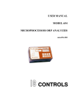
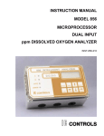
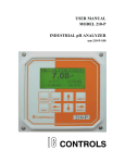
1
INSTRUCTION MANUAL MODEL 877 INTELLIGENT CHLORINE ANALYZER pH/ORP METHOD IC CONTROLS CONTENTS 877 Menu . . . . . . . . . . . . . . . . . . . . . 4 Power-up . . . . . . . . . . . . . . . . . . . . . 6 Analyzer Startup Tests . . . . . . . . . . . . 6 Calibration Settings Retained . . . . . . . . . 6 Moving Around in the Menu . . . . . . . . . . 7 Easy to Use—Remembers Where You Were 7 Home Base—Press Sample . . . . . . . . . 7 Four Arrow Keys . . . . . . . . . . . . . . . 8 AUTO and MANUAL Keys . . . . . . . . . . 8 Edit Mode . . . . . . . . . . . . . . . . . . . . 9 Security . . . . . . . . . . . . . . . . . . . . . 11 Entering a Password . . . . . . . . . . . . . 11 Application Information . . . . . . . . . . . . . 13 Chlorine Chemistry . . . . . . . . . . . . . . 13 Chlorine and pH . . . . . . . . . . . . . . . . 13 Terminology . . . . . . . . . . . . . . . . . . 15 Disinfectant Properties of Chlorine . . . . . . 15 Relation of ORP and Chlorine . . . . . . . . 16 Water Poise and Calibration . . . . . . . . . 16 Chlorine Calibration . . . . . . . . . . . . . . . 17 Calibrating the Chlorine Measurement . . . . 17 pH and Temperature impact on Chlorine . . . 19 Manual Temperature Compensation . . . . . 19 Manual pH Compensation . . . . . . . . . . 19 pH Calibration . . . . . . . . . . . . . . . . . . 20 pH Calibration Kit . . . . . . . . . . . . . . . 20 Calibrating the pH Input . . . . . . . . . . . . 21 Standardizing — Single-Buffer Calibration . . 21 Calibrating – Two-Buffer Calibration . . . . . 23 Selecting a Buffer . . . . . . . . . . . . . . . 23 pH Electrode Maintenance . . . . . . . . . . 24 Output Hold . . . . . . . . . . . . . . . . . . 24 Grab Sample pH or Manual Offset and Slope 25 Temperature Compensation for pH . . . . . . 26 pH Buffers . . . . . . . . . . . . . . . . . . . 27 ORP Calibration . . . . . . . . . . . . . . . . . 28 ORP Calibration Kit . . . . . . . . . . . . . . 28 About ORP Calibration . . . . . . . . . . . . 29 Selecting a Standard for Calibration . . . . . 29 Doing an ORP Calibration . . . . . . . . . . 29 ORP Electrode Maintenance . . . . . . . . . 30 Manual Adjustment of Offset . . . . . . . . . 30 Dual 4 to 20 mA Output Signals . . . . . . . . 31 Page 2 INST877-133 Alarm Functions . . . . . . . . . . . . . . . . Standby Mode . . . . . . . . . . . . . . . . . Error Messages . . . . . . . . . . . . . . . . IC Net Features . . . . . . . . . . . . . . . . . Wiring and Enabling . . . . . . . . . . . . . Internal Data Log . . . . . . . . . . . . . . Display Prompts . . . . . . . . . . . . . . . . Glossary . . . . . . . . . . . . . . . . . . . . Configuration of Program . . . . . . . . . . . Electrode Instructions . . . . . . . . . . . . . Preparation for use . . . . . . . . . . . . . Calibration for pH Measurement . . . . . . . Electrode Storage . . . . . . . . . . . . . . Restoring Electrode Response . . . . . . . Troubleshooting the pH Sensor . . . . . . . Isolating the Problem . . . . . . . . . . . . Analyzer Problem Troubleshooting . . . . . pH Electrode (Sensor) Troubleshooting . . . Electronic Hardware Alignment . . . . . . . . Calibration of 4 to 20 mA Outputs. . . . . . . Repair and Service . . . . . . . . . . . . . . . Appendix A—Enabling Security . . . . . . . Appendix B—Default Settings . . . . . . . . Appendix C—Installation . . . . . . . . . . . Analyzer Mounting . . . . . . . . . . . . . . Sensor Mounting . . . . . . . . . . . . . . . Analyzer Wiring . . . . . . . . . . . . . . . Configure your program . . . . . . . . . . . Appendix D—Parts List . . . . . . . . . . . . Industrial Products Warranty . . . . . . . . . Drawings . . . . . . . . . . . . . . . . . . . . Display Schematic . . . . . . . . . . . . . . Microprocessor Board Schematic . . . . . . Microprocessor Board Component Location Input Schematic . . . . . . . . . . . . . . . Current Output and Alarms Schematic . . . Power Supply Schematic . . . . . . . . . . Main Board Component Location . . . . . . Wiring Diagram . . . . . . . . . . . . . . . Mounting Dimensions . . . . . . . . . . . . 2" Pipe/Wall Mounting Kit . . . . . . . . . . Panel Mounting Kit . . . . . . . . . . . . . . Index . . . . . . . . . . . . . . . . . . . . . . 877 Instructions 32 35 36 41 41 41 43 44 45 47 47 47 48 48 49 49 50 51 52 53 54 55 57 58 58 58 58 59 60 61 62 62 63 64 65 66 67 68 69 70 71 72 73 IC CONTROLS 877 Instructions Page 3 IC CONTROLS 877 Menu CALIBRATE Page 4 877 Instructions IC CONTROLS * * * * 877 Instructions Page 5 IC CONTROLS Power-up Power-up If the analyzer is new and has not been installed, follow the procedures described in Installation, Electronic Hardware Alignment and Configuration of Program before mounting. Mounting and wiring procedures for new installations vary with equipment options—see drawing section for instructions. If the analyzer has been previously installed all that is required is to attach the electrode to the analyzer and then to turn on the power. The analyzer will go through its automatic startup procedure any time power to the analyzer was lost for more than a few seconds. The startup procedure initializes the analyzer program, performs error checking, and then proceeds to display the pH and operate the analyzer normally. All program settings, calibration settings, and defaults will have been remembered by the analyzer, as the memory is none volatile. Analyzer Startup Tests The startup procedure will begin by alternately flashing [ tESt ] and [ —— ] and blinking the top LED while performing the memory tests. The analyzer will then display in sequence the analyzer number, in this case [ 877 ], any software option numbers, and the program version number, e.g.[ 1.30]. The program then proceeds to the display test which will light each of the implemented display segments in turn. At the same time each of the LEDs will be lighted in turn. If the analyzer passes all the tests then the hardware is functioning properly, and the analyzer with proceed to display free chlorine. If the analyzer displays +Err or -Err this indicates that the input is offscale. The error LED will be lighted as long as any input is offscale. An offscale error can indicate that the electrode is not in solution, is off scale, or is not connected properly. If the error LED remains lighted go to the error display section (select [ Err ] from main menu) to see what errors have been detected by the analyzer. Calibration Settings Retained If the analyzer was calibrated previously then the analyzer will use the calibration settings from the last successful calibration, otherwise default settings are used. Error and caution messages generated during the last calibration will remain in effect. IC CONTROLS recommends a full chemical calibration of pH, ORP, and chlorine after initial startup. See calibration section. Analyzer settings and parameters can be viewed and/or changed at any time. Refer to the menu; the areas shaded in dark gray indicate program settings. Page 6 877 Instructions Moving Around in the Menu IC CONTROLS Moving Around in the Menu The layout of the program is shown in the menus found on pages 4 and 5. The menu can be used as a quick reference guide to all the analyzer functions. Easy to Use—Remembers Where You Were The analyzer remembers where home base is, it remembers which areas of the menu you used last, and it will loop around columns in the menu for you. You can explore the menu with the arrow keys to find any capability and simply press SAMPLE to return to home base. Then use the Right arrow key to return to exactly where you were. Home Base—Press Sample The SAMPLE key’s function is to give you a known starting point displaying the home sample or home input . The SAMPLE key is usable from anywhere in the menu. The HOCl display is the home base display for the analyzer. The analyzer’s inputs are arranged underneath each other at the left-hand side of the menu. Use the Up or Down arrow key to display each of the readings in turn. From anywhere in the menu the SAMPLE key can be used to return to the pH or home sample display. The program will safely abort whatever it was doing at the time and return to displaying the pH sample. Features 1. The analyzer has a built-in timer which returns the program to displaying the home base if no key has been pressed for 15 minutes. This time-out has the same effect as pressing the SAMPLE key. If security has been enabled, as well, the timeout will change the access level back to 0 or 1 automatically, which gives the user read-only access. The user will have to enter an appropriate password to go to a higher access level. If the alarm override was activated using the manual key, the analyzer will return to auto mode and the alarm contacts will be re-activated. The green AUTO LED will stop blinking and remain on steady to indicate auto alarm mode is active. 2. When displaying the home base, you can press Left to show which of the samples is displayed. Pressing Right displays the same sample again. 877 Instructions Page 7 IC CONTROLS Moving Around in the Menu Four Arrow Keys The four arrow keys on the keypad are used to move around in the menu. The same keys can have other functions as well, e.g. see under Edit Mode, but when moving from frame to frame in the menu these keys work as expected. Example: Press SAMPLE to make sure that we are at home base. Press the right arrow key. One of the prompts in the column starting with [ out ] will be displayed. Use the Up or Down arrow keys to display the prompt above or below. If the prompt at the top or the bottom is displayed the program will loop around. Press the Up or Down key until [ AL ] is displayed. Press the Left key to return to the pH display. Press the Right key again and [ AL ] will be displayed. AUTO and MANUAL Keys The AUTO and MANUAL keys are used to implement the alarm override feature on analyzers that do not use the PID option. Refer to the Alarm Override heading in the Alarm Functions section for a description of these key functions. Page 8 877 Instructions Edit Mode IC CONTROLS Edit Mode Edit mode is used to change a numeric value or to select between different options. The values and settings which can be edited are identified by the darker shading in the menus. Any frame which has a white background cannot be modified by going into edit mode but can be viewed. Editing by Selecting a Setting Examples of selecting a value are on/off settings and switching between different alarm types. Editing a value is like picking an option from a list. You can see only one item on the list at a time. Example: Turn alarm A off. From the menu select [ AL ] [ AL.A ] [ ON.OF ]. The analyzer will now display either [ ON ] or [ OFF ], which are the two choices. To change the setting, press ENTER to go into edit mode. The display will start blinking. Use the up or down arrow key to switch between the possible options, which in this case are [ ON ] and [ OFF ]. When [ ON ] is displayed, press ENTER again to accept the new setting and leave edit mode. Editing a Numeric Value Numeric values such as an alarm setpoint are adjusted by going into edit mode and then adjusting each digit until the new value is displayed. Use the left and right arrow keys to move between digits and use the up and down arrow keys to adjust each digit. When you press ENTER to go into edit mode two things will happen. First, the last digit will start blinking to show that this digit can be changed. Second, any blank spaces will change to zeros and a plus or minus sign will appear. Now each digit can be accessed. Change between positive and negative numbers by switching between plus and minus sign using the up or down arrow key when the plus/minus segment is blinking. Press ENTER again to leave edit mode. Before the new value is changed, the analyzer will check the new value to make sure that it is within range. If the new value is lower than the lowest value allowed for that frame then the analyzer will use the lowest allowable value instead of the new value you entered. Likewise if the new value you entered is higher than allowable then the highest allowable value is used instead. The analyzer will display whatever value it has stored in memory. Example: Change the alarm A setpoint from 20 to 10. From the menu select [ AL ] [AL.A] [ SEt ]. The current setpoint (e.g. [ 20 ]) will be displayed. Press ENTER to enter edit mode. The display will change to [ + 0020] and the last digit will start blinking. Press CANCEL to move left one digit. The second digit from the end will now be blinking. Press the down arrow key to change the ‘2’ to ‘1’. Press ENTER again and the display will change from [ + 0010] to [ 10 ] indicating that the new value has been stored in memory. The alarm A setpoint has now been changed from 20 to 10. Press the left arrow key to display [SEt ], [AL.A] etc. 877 Instructions Page 9 IC CONTROLS Edit Mode Summary of Key Functions in Edit Mode Enters edit mode. The entire display or a single digit will blink to indicate that the analyzer is in edit mode. Press the Enter key again to leave edit mode and accept the new value. Adjusts blinking digit upward or selects the previous item from the list. If a ‘9’ is displayed then the digit will loop around to show ‘0’. Adjusts blinking digit downward or selects the next item from the list. If a ‘0’ is displayed then the digit will loop around to show ‘9’. Numeric Values only: move to the right one digit If blinking is already at last digit display will loop to the +/- sign on the left. Numeric Values: move left one digit. If blinking is at the +/sign then blinking goes to the last character. Settings: restore the initial value if it was changed. Otherwise leave edit mode without doing anything. Page 10 877 Instructions IC CONTROLS Security Security The analyzer has a built-in password protection system. This security system is disabled by default. If password protection is not enabled then you have unrestricted access to all analyzer settings available through the menu as described in this manual and you can safely ignore this section. Having security disabled gives you the same access to the program as being at access-level 2 at all times. By default security is disabled. To enable the security system, first follow the instructions in “Appendix A—Enabling Security.” access-level description 0 View-only access to all settings 1 Access to all settings except for configuration menu. Usage: operator access. no changes can be made to configuration and passwords cannot be changed. 2 Access to all settings. This gives you the same access to the program as when password security is not enabled. Passwords can be changed. Usage: installation, management. With security enabled anyone can view settings anywhere in the program. When you do not have proper access rights, the program will display [ PASS ] for 2 seconds, indicating that you must first enter a proper password before you are allowed to proceed. Entering a Password With security enabled, select [ PASS ] from the main menu. The analyzer will display [ 0000 ]. Use the arrow keys to display your level 1 or level 2 password, then press ENTER . The program will display [ good ], followed by your access level before returning to the main menu. If an incorrect password was entered the program displays [ bAd ] instead. Refer to the chart at left to determine how the program validates a password. You will now have level 1 or level 2 access for as long as you are working with the analyzer. The access level will 877 Instructions Page 11 IC CONTROLS Security automatically be restored to level 0 after no key has been pressed for 15 minutes. This 15-minute timeout will also redisplay the main sample. It is good practice to return the analyzer to level 0 access (or level 1 access if password 1 is set to “000”) when you have finished using the analyzer. This is accomplished by selecting [ PASS ] from the main menu, then pressing Enter with [ 0000 ] displayed. Passwords—A Quick Tour Assuming that password 1 is defined and we are at access level 0, try changing the output 1 low setting. Select [ out ] [ out1 ] [ LO ] from the menu. The current value will display. Press Enter to go into edit mode. The analyzer will display [ PASS ] for 2 seconds because we need to enter a password first. Level 1 security is needed to change this setting. Select [ PASS ] from the main. Change the displayed value to the level 1 password, then press Enter. The analyzer will display [ good ], followed by [ ACC.1 ], indicating that the password is valid and that we now have level 1 access. Try changing the output 1 low setting again. You will find that this time we can go into edit mode unhindered. Before walking away from the analyzer, we should disable level 1 access to prevent unauthorized use of the analyzer. Select [ PASS ] from the menu again, then press Enter with [ 0000 ] displayed. The analyzer will display [ ACC.0 ] indicating that we have returned to the lowest access level. Page 12 877 Instructions Application Information IC CONTROLS Application Information Chlorine Chemistry pH is an important variable in chlorine-water systems, since it determines what form the chlorine takes. When chlorine gas is dissolved in water, it hydrolyzes rapidly according to equation 1. This reaction occurs very rapidly, in only a few tenths of a second at 18°C. 1) Cl2 + H2O —> HOCl + HCl Since HCl is a strong acid, addition of gaseous chlorine to water results in a lowering of the pH from the acidic HCl by-product. The important product of reaction (1) is HOCl or hypochlorous acid. Hypochlorous acid is the killing form of chlorine in water. Hypochlorous acid is unstable because the chlorine molecule is lightly bound and therefore will react quickly. Free available chlorine, or free chlorine, is HOCl or hypochlorous acid. Free chlorine (HOCl) is taste free and aggressive against germs and organic compounds. Chlorine supplied as sodium hypochlorite, calcium hypochlorite, or bleach is in a basic form. When a base is present, a different reaction sequence occurs: 2) NaOCl + H2O —> HOCl + Na+ + OH3) Ca(OCl)2 + 2H2O —> 2HOCl + Ca++ + 2OHIn any hypochlorite solution the active ingredient is always hypochlorous acid. Then once HOCl and OH- are formed an additional reaction occurs: 4) HOCl + OH- <—> OCl- + H2O The proportion of chlorine, hypochlorous acid, and hypochlorite ion in solution depends on primarily on pH and somewhat on temperature. The different forms of chlorine are named as follows: Cl2 = chlorine HOCl = hypochlorous acid OCl- = hypochlorite ion At atmospheric pressure and 20°C the maximum solubility of chlorine is about 7395 mg per liter or 7.395 ppm. Chlorine and pH The most important reaction in the chlorination of an aqueous solution is the formation of hypochlorous acid. The hypochlorous acid form of chlorine is very effective for killing germs. Hypochlorous acid is a ‘weak’ acid, meaning that it 877 Instructions Page 13 IC CONTROLS Application Information tends to undergo partial dissociation to form a hydrogen ion and a hypochlorite ion. Once in a water environment HOCl tends to dissociate into H+ and OClions. 5) HOCl <—> H+ + OCl- In waters between 5 and 8.5 pH the reaction is incomplete and both species are present to some degree. Since H+ is one of the ions that is formed and its concentration is expressed as pH, it follows that changing pH levels will influence the balance of this reaction and with it the availability of hypochlorous acid for reaction. In a water environment the water pH will therefore affect the chemistry of chlorine through its pH sensitivity. As pH rises this is important. 6) H2O <— H+ + OH- (preference is right-to-left) Three things follow from this form of ionization. 1. Since the tendency of these two ions to react and form H2O is much stronger than the tendency of water to break down into the ions, it follows that as the pH rises and there are fewer H+ ions and more OH- ions. 2. The H+ released by the breakdown of HOCl (equation 5) react to form water (equation 6) and leave behind residual OCl- (hypochlorite) ions. Hypochlorite does not react readily, so the chlorine is weaker. 3. However, if the pH goes down and H+ ions become readily available again, the OCl- ions revert to HOCl, which is the killing form of chlorine. This pH change has been known to cause surprise downstream fish kills. Note: HOCl + OCl- is total free chlorine Page 14 877 Instructions Application Information IC CONTROLS Terminology In the industry there are a number of terms used to indicate the various forms of chlorine that are of interest. These terms tend to be used rather loosely and not necessarily consistently. For that reason, we will define the following terms for purposes of this instruction manual and the 877 analyzer: Free Available Chlorine refers to the hypochlorous acid (HOCl) form of chlorine only. It is said to be free available because it is the free, uncombined form of chlorine that is effective for killing. Total Free Chlorine refers to the sum of hypochlorus acid (HOCl) and hypochlorite ion (OCl-). The hypochlorite ion is not effective for killing, but it is in a free form. All of the total free chlorine would be in the form of hypochlorous acid if the pH is low enough. Combined Chlorine refers to chlorine which is not readily available, for example chlorine combined as chloramines or organic nitrogen is not an effective disinfectant and will not readily convert to hypochlorous acid or hypochlorite ion. Total Residual Chlorine refers to the sum of total free chlorine and combined chlorine. In environmental studies low total residual chlorine is of particular interest to ensure no downstream consequences for aquatic life. Disinfectant Properties of Chlorine Chlorine is known to be a good disinfectant, it is able to kill living matter in water such as bacteria, cysts, and spores. Exactly how chlorine works to kill is not known. Studies do agree, however, that certain forms of chlorine are more effective than others. Whatever the chemical reaction, it is also generally agreed that the relative efficiency of various disinfecting compounds is a function of the rate of diffusion of the active agent through the cell wall. Factors which affect the efficiency of destruction are: • • • • • • Nature of disinfectant (kind of chlorine residual fraction) Concentration of disinfectant Length of contact time with disinfectant Temperature Type and concentration of organisms pH HOCl hypochlorous acid (free available chlorine) is the most effective of all the chlorine forms. Hypochlorous acid is similar in structure to water. The germicidal efficiency of HOCl is due to the relative ease with which it can penetrate cell walls. This penetration is comparable to that of water, and can be attributed to both its modest size and to its electrical neutrality. The concentration of hypochlorous acid is dependent on the pH, which establishes the amount of dissociation of HOCl to H+ and OCl- ions. Lowering the temperature of the reacting solution suppresses the dissociation; conversely raising the temperature increases the amount of dissociation. ORP vs Kill time of E. Coli 877 Instructions The rate of dissociation of HOCl is so rapid that equilibrium between HOCl and the OCl- ion is maintained, even though the HOCl is being continuously used up. Page 15 IC CONTROLS Application Information The OCl- ion hypochlorite ion form of chlorine is a relatively poor disinfectant because of its inability to diffuse through the cell wall of microorganisms. The obstacle is the negative electrical charge. Relation of ORP and Chlorine The graph below illustrates the logarithmic relationship between the ORP and ppm of chlorine. The measurement of ORP is the reading of a voltage potential between the reference electrode and the platinum ORP sensing electrode. The voltage generated by the sample is proportional to the concentration of free available chlorine. The 877 uses a polynomial formula to calculate the total free chlorine value, which effectively adds the hypochlorite ion concentration. This calculation requires that the analyzer know the pH and temperature of the sample. Water Poise and Calibration Every individual water source will have somewhat different dissolved chemical composition which can affect the background ORP value that is seen at the same chlorine concentration. The 877 chlorine calibration is designed to determine this characteristic “poise” (ORP balance, stability) of the water and record this poise as shift in the ORP value. The “poise” of a water sample tends to vary from water source to water source, to be stable for any particular water source, and to affect the zero point of the ORP vs chlorine curve and not the span. Therefore only a single-point zero-shift calibration is performed. This poise is usually best determined after the system has been in operation for at least 24 hours and while normal operating conditions are observed. Page 16 877 Instructions IC CONTROLS Chlorine Calibration Chlorine Calibration Calibrating the Chlorine Measurement The 877 Chlorine reading is calibrated by grab sample, an easy method of standardizing the chlorine measurement without taking the electrodes out of the sample. Grab sample standardization method requires the user to determine the actual total free chlorine concentration of the sample using a different method. A7010001 Chlorine Calibration Kit When grab sample calibration is used it is the responsibility of the user to ensure that the grab sample taken and the total free chlorine value recorded for it are accurate. Caution: Calibrate pH FIRST Since chlorine is pH-dependent, the chlorine calibration should be done second, after pH calibration. A change in pH calibration after a chlorine calibration was completed would destroy the chlorine calibration. ORP calibration can be skipped as its correction is folded into the chlorine calibration. A chlorine calibration kit part # A7010001 is available from IC CONTROLS which makes it relatively simple to get a total free chlorine measurement for calibration purposes in the 0-1 or 1-5 ppm concentration ranges. The calibration kit uses a reagent which develops a violet color which is proportional to the amount of total free chlorine in the sample. The kit contains 30 ampoules, sample cup, and low & high range comparators. Note: Keep the kit closed when not in use. The comparators need to be stored in the dark. Standardizing Chlorine 1. Press SAMPLE to display the [ tFCl ] reading. Press SELECT to reach the first menu, then use the up or down arrow key to display [ CAL ]. 2. Press SELECT then the up or down arrow to display [ tFCl ]. 3. From [ tFCl ] display press SELECT to [ Cal ] then SELECT again to [ Get ] then SELECT again to flashing [ DO ] LEAVE ANALYZER FLASHING!. 4 Obtain, from the analyzer outlet, a representative grab sample cup full of water, then immediately go and press ENTER on the 877. 5. Take an ampoule from the kit and place the ampoule’s tapered tip into one of the four depressions in the bottom of the sample cup. Snap the tip by pressing the ampoule towards the side of the cup. The sample will fill the ampoule and begin to mix with the reagent. Note: a small bubble of inert gas will remain in the ampoule to facilitate mixing. Caution: Do not break the tip of the ampoule unless it is completely immersed in your sample. Accidentally breaking the tip in the atmosphere may produce a “jack-hammer” effect, shattering the ampoule. Wear eye protection when working with these ampoules. 877 Instructions Page 17 IC CONTROLS Chlorine Calibration 6. Remove the fluid-filled ampoule from the cup. Mix the contents of the ampoule by inverting it several times, allowing the bubble to travel from end to end each time. 7. Wipe all liquid from the exterior of the ampoule and wait 1 minute. 8. After waiting 1 minute, use the appropriate comparator to determine the level of chlorine in the sample. Write down the Chlorine Value. Low-range Comparator 0-1 ppm High-range Comparator 1-5 ppm The ampoule is placed in the center tube, flat end downward. The top of the cylinder is then directed toward a source of bright light while viewing from the bottom. Hold the comparator in a nearly horizontal position and rotate it until the standard below the ampoule shows the closest match. The comparator should be illuminated by a strong white light directly above the comparator. The filled ampoule should be placed between the color standards for viewing. It is very important that the ampoule be compared by placing it on both sides of the standard tube before concluding that it is darker, lighter, or equal to the standard. 9. Install the Chlorine Calibration value determined in step 8 into the 877. Press SAMPLE then SELECT to [ tFCl ], then SELECT to [ CAL ], then SELECT SELECT to [ Get ], then up arrow to [ SEt ], then again to numbers display, then ENTER to get [flashing numbers]. Edit the ppm total free chlorine value and change it to the new value from step 7. When [flashing value] is [step 7 Chlorine Value] that you determined, Press ENTER to get analyzer to take value, then SELECT to flashing [ DO ], then press ENTER again to get the 877 to install the Chlorine Calibration and water poise. [Done] appears. Method for breaking the ampoule Using the low-range comparator 10 Press SAMPLE to display [HOCl ] or free chlorine (residual) in mg/l or ppm . Write down this value. 11 Press down arrow to display [HOCl + OCl ] or total chlorine (residual) in mg/l or ppm. Write down this value. 12 Press SELECT then up arrow to [ tFCl ], then SELECT plus up arrow to [Pois ], then SELECT to [numbers] (Poise in mV). Write down this value Poise records will show how your water changes from season to season. Your 877 analyzer is now reading Chlorine and tracking Chlorine changes in your water. Using the high-range comparator Page 18 877 Instructions Chlorine Calibration IC CONTROLS pH and Temperature impact on Chlorine The measurement of the chlorine concentration is done first of all by the ORP sensing electrode, but the Chlorine chemistry of the sample will change both with temperature and with pH. The figure at left shows how the relative concentrations of hypochlorous acid and hypochlorite ion shift with a change in the pH. This same relationship is also dependent on the temperature of the solution, as the curves will shift with changes in the temperature. The 877 has been designed to compensate for these changes in pH and temperature by compensation for both parameters using the pH and temperature sensors. By default the 877 analyzer will automatically compensate for pH and temperature using the pH and temperature inputs. For this reason it is important to ensure that both these inputs are calibrated and in good working order. A method has been provided in the analyzer program to change the compensation method for both pH and temperature compensation from automatic to manual. Providing a method of manual temperature or pH compensation allows the analyzer to continue measuring free available chlorine and total free chlorine in case either the temperature or pH sensor is malfunctioning or absent. Manual Temperature Compensation From the menu select [ tFCl ] [ tc ]. At this point either [ Auto] (for automatic temperature compensation), or [ SEt ] (for manual temperature compensation setpoint) will be displayed. To change the setting from [ Auto ] to [ SEt ] press Enter to edit the current setting. The display will start blinking, indicating that a selection needs to be made. Use the up and down arrow key to display [ SEt ]. Press Enter to select manual temperature compensation. With [ SEt ] as the current display, press Select to display the temperature setting for manual temperature compensation. If the current value needs to be changed, press Enter to edit the current setting. The display will start blinking. Use the up and down arrow keys to display the desired temperature for manual temperature compensation. Press Enter to accept the currently displayed value. Manual pH Compensation From the menu select [ tFCl ] [ PH.C ]. At this point either [ Auto] (for automatic pH compensation), or [ SEt ] (for manual pH compensation setpoint) will be displayed. To change the setting from [ Auto ] to [ SEt ] press Enter to edit the current setting. The display will start blinking, indicating that a selection needs to be made. Use the up and down arrow key to display [ SEt ]. Press Enter to select manual temperature compensation. With [ SEt ] as the current display, press Select to display the pH setting to be used with manual pH compensation. If the current value needs to be changed, press Enter to edit the current setting. The display will start blinking. Use the up and down arrow keys to display the desired pH for manual pH compensation. Press Enter to accept the currently displayed value. 877 Instructions Page 19 IC CONTROLS pH Calibration pH Calibration pH Calibration Kit pH Calibration Kit P/N A1600050 This kit conveniently packages the requirement for buffer calibrations in amounts for easy use, along with the necessary utensils and accessories. These items are provided in durable plastic. This way, you are assured reliable and accurate results, and at the same time the technician’s job is easier. This kit is a one-year supply of all maintenance items and include one each of the following: Description Part No. Size 4.00 pH Buffer, Red 7.00 pH Buffer, Green 10.00 pH Buffer, Blue Electrode Wash Solution Beakers Squeeze Bottle Deionized Water A1100051-6P A1100052-6P A1100053-6P A1100091 A1100020 (x4) A1100014 A1100192-6P 6 x 500 mL 6 x 500 mL 6 x 500 mL 1 x 500 mL 1 x 250 mL 1 x 120 mL 6 x 500 mL About Calibration . . . When you buy from IC CONTROLS our commitment to you includes the standards to properly clean and calibrate the equipment. Our commitment to you does not stop when we ship the equipment, it continues until you have calibrated the analyzer system, are satisfied with the results, and beyond. To assist you in obtaining reliable results, IC CONTROLS developed calibration and cleaning procedures and manufactures and packages the necessary standards, buffers and supplies in convenient usage quantities. If you need assistance with calibration techniques or any other matter, our application development laboratory specialists are only a toll-free phone call away for advice and/or laboratory simulation of your problem.. Buy from IC CONTROLS because you get outstanding customer support as well as quality industrial equipment; in short, REAL SOLUTIONS. Page 20 877 Instructions pH Calibration IC CONTROLS Calibrating the pH Input Soln GND ORP pH pH & ORP Sensor Connectors The pH analyzer is calibrated using one of several methods. A one-point, “Single-Buffer Calibration”, or standardization adjusts the electrode offset while maintaining the previous slope. Two-point calibration combines the standardization with the results of the Two-Buffer calibration and calculates the pH Efficiency (or slope) as well as the offset. Grab sample calibration is a method to adjust the offset where it is difficult to remove the pH electrode for calibration. A calibration is easily accomplished by selecting an appropriate buffer, placing the electrode in the buffer solution, and letting the analyzer do the rest. The Analyzers automatic stability testing takes most of the guesswork out of deciding whether a reading is acceptable or not. Internal diagnostic tests will activate “caution” or “error” messages if faulty operation is detected. Errors detected during calibration will not cause the analyzer to lock up. 877 automatic output hold. NOTE: For pH BUFFERING the SOLUTION GROUND must contact the buffer! Output hold goes into effect as soon as SELECT is pressed with [ CAL ] displayed. The output hold feature avoids false alarms and erratic signal output caused by a routine calibration. Buffers automatically recognized by the 877 are: green 7.00 pH buffer, part number A1100052; red 4.01 pH buffer, part number A1100051; blue 10.0 pH buffer, part number A1100053. These buffers come in 500 mL bottles and are available in six-packs. pH Buffering in a beaker, with Solution Ground Soln GND pH The 877 uses pickup resistant differential preamp technology. This measures the pH and reference electrodes separately using a solution ground to complete the circuit. The two signals are then subtracted thus canceling electrical pickup signals. The Solution Ground connection is installed in the M2 flowcell. To buffer pH in a beaker both the pH electrode and solution ground must be in the beaker. Alternately a jumper wire can be hooked between the cell solution ground and the beaker liquid. See pH Buffer Calibration. Standardizing — Single-Buffer Calibration Standardizing the analyzer causes the analyzer to calculate the offset for the pH BUFFER CALIBRATION CALIBRATE pH electrode. The pH efficiency determined during the last buF2 calibration will 877 Instructions Page 21 IC CONTROLS pH Calibration continue to be used. 1. Press SAMPLE to display the Chlorine reading. Press SELECT to reach the first menu, then use the up or down arrow key to [ PH ]. Press SELECT to reach the second menu, then use the up or down arrow key to display [ CAL ]. 2. Press SELECT again, then use the up or down arrow key to display [ buF1]. 3. Press SELECT again to reach the next menu. We now choose a buffer with which to standardize the analyzer, typically 7.0 pH. SELECT either auto detection, one of the standard buffers (4, 7, 10) , or a custom value. For further details see Selecting a Buffer for an explanation of the buffer selection process. 4. Place the electrode in the buffer solution, then press SELECT again to start the calibration process. The display will show a flashing pH reading to indicate that the analyzer intelligence is reading pH and testing for stability. As soon as the electrode has stabilized, the new electrode offset will be calculated and entered in memory, plus the display will stop flashing and the steady value will be the temperature corrected Buffer pH. 5. Press SAMPLE to display the Chlorine reading, then the up or down arrow key to the pH display. Calibration may be redone or started over at any time. Press CANCEL to display the selected buffer (e.g. [ Auto ]), then SELECT to restart the calibration. It is possible to rush the analyzer. The ENTER key may be pressed before the electrode has stabilized, forcing the analyzer to calibrate using the current pH. What if the display shows [ E.??] or [ CA.??] ? If the analyzer intelligence detects or suspects any problems during calibration, an “E” (error) or a “CA” (caution) message will appear. Refer to the heading Error Messages for the meaning of each message. E messages: If an error has occurred, the standardization was not successful (or bad). The analyzer keeps the values from the last calibration, (it does not install the bad calibration values). Press any key to acknowledge the error and continue. The analyzer will return to the buffer menu and display the selected buffer. Make sure the buffer you used and the buffer selected are the same and retry the calibration. CA messages: If a potential problem has been detected, (e.g. there is a large offset), then the analyzer calibration was successful. The caution message simply informs the user that poor performance is suspected. Press the SELECT key to acknowledge the caution and display the temperature corrected Buffer pH value, after a caution message has appeared. Press SAMPLE to display the chlorine reading, then the up or down arrow key to the pH display. Page 22 877 Instructions Figure 1 First buffer menu sequence pH Calibration IC CONTROLS Calibrating – Two-Buffer Calibration Calibrating the analyzer involves calculating both the offset and the electrode efficiency or slope for a particular electrode pair. The electrode efficiency will be calculated as a percentage of theoretical Nernst response. 1. Calibrate with the first buffer, using 7.0 pH buffer, by following the procedure for standardizing. 2. For the second buffer, Press SAMPLE to display the Chlorine reading. Press SELECT to reach the first menu, then use the up or down arrow key to display [ pH ]. Press SELECT again, then use the up or down arrow key to display [ CAL]. 3. Press SELECT again to reach the next menu, then use the up or down arrow key to display [ buF2 ].. We now choose a buffer with which to slope the analyzer, typically 4.0 or 10 pH. The second buffer should be at least 1 pH unit higher or lower than the buffer used for standardize. SELECT either auto detection, one of the standard buffers (4, 7, 10) , or a custom value. For further details see Selecting a Buffer for an explanation of the buffer selection process. 4. Place the electrode in the buffer solution, then press SELECT again to start the calibration process. The display will show a flashing pH reading to indicate that the analyzer intelligence is reading pH and testing for stability. As soon as the electrode has stabilized, the new electrode efficiency or slope will be calculated and entered in memory, plus the display will stop flashing and the steady value will be the temperature corrected Buffer pH. If an error occurs at this point, the standardization ([ buF1] calibration) will be kept, but the efficiency will not be installed. Either retry the efficiency calibration with a second buffer ([ buF2]), or resume normal operation using only the standardization. 5. Press SAMPLE to display the Chlorine reading, then the up or down arrow key to the pH display. Figure 2 Second buffer menu sequence 6. To verify that the Nernst efficiency (slope) has been calculated, press SELECT twice, then use the up or down arrow key to display [SLOP] in the pH menu. Press SELECT again to display the slope efficiency. A properly functioning electrode will have an electrode efficiency of between 80 and 102 per cent of Nernstian or theoretical response. Selecting a Buffer The best First buffer for starting calibration is 7.0 Buffer since it has the electrodes at the 0mV point, so electronic zero and chemical zero are both therefore correct. Select the Second buffer to be on the other side of your expected pH measurement, (example: pH typically 7.0 to 8.5 then select 10.0 buffer). Both the chemical efficiency versus perfect Nernst response and the electrode slope or span will be correctly set. Automatic buffer detection provides the simplest and most accurate method of calibrating the 877 analyzer. The analyzer has been programmed to recognize the three buffers most commonly used for calibration: 4, 7, and 10 pH. Simply place the electrodes in the buffer solution and the analyzer will use the correct buffer, allowing for an offset of up to ± 1.3 pH units. 877 Instructions Page 23 IC CONTROLS pH Calibration Temperature Dependence of Buffers The pH of a solution is dependent on temperature. To achieve greater accuracy, the temperature-compensated values for the 4, 7, and 10 auto-recognized pH buffers are calculated by the analyzer. If manual temperature compensation has been selected then the manual temperature compensation setpoint is used as the buffer temperature. The graphs show the temperature-dependence of the standard buffers. The t-curves have been programmed into the analyzer. The actual pH value of each of the three standard buffers will be used. Example: Calibrate with the 4.01 (at 25°C) pH buffer. The temperature of the buffer is 50°C. The analyzer will use the pH value of 4.05. Incorrect Auto Buffer or Over 1.5 pH Standardize If the offset is known to be greater than ± 1.3 pH units or if the analyzer is thought to have selected the wrong buffer using automatic buffer recognition, it is possible to specify which buffer is to be used. When [ 4.01 ], [ 7.00 ], or [ 10.0 ] is selected, temperature-compensated values are used and an offset of ± 4 pH units is allowed. If manual temperature compensation has been selected then the manual temperature compensation setpoint is used. Other Buffer Values or Custom Buffers If a buffer with a pH value other than 4, 7, or 10 pH is to be used, select [ cuSt ] (custom value), then enter a value between 0 and 14 pH. Buffer values entered this way are not temperature-compensated; the buffer is assumed to have the specified pH value at the current temperature. Offsets of up to ± 4 pH units are allowed. pH Electrode Maintenance The electrode needs to be calibrated periodically to maintain an accurate pH measurement. Depending on the process, the electrode may need to be calibrated more frequently, e.g. weekly or even daily. Frequent calibration is important if an accurate pH measurement is required. Over time electrode performance will degrade. The glass bulb becomes less responsive to pH and the reference electrode becomes depleted. See pH Electrode Instructions; restoring electrode response for more detail. Depending on the harshness of the process, the electrodes will need to be replaced after several years of use, or less. If you want to clear the error indicator LED after a pH calibration then follow the procedure under Acknowledging Error Messages. Output Hold The 877 features an automatic output hold. Output hold goes into effect as soon as SELECT is pressed when [ CAL] is displayed. The output hold feature avoids false alarms and erratic signal output that would caused by a routine calibration. Output hold has the following effect: — 4-20 mA output signals for pH, HOCl, and TFCl are frozen at their current levels — alarms for pH, HOCl, and TFCl are temporarily disabled. If the output signal for pH is not acceptable at the value found, it can be changed for the duration of the calibration. Select [ Hold ] from the menu to Page 24 877 Instructions pH Calibration IC CONTROLS display the pH value used by the analyzer to determine the output signal. Use the normal editing procedure to change the pH value used for output hold. The output hold remains in effect for the duration of the calibration, that is, the output hold is disabled when the [ CAL ] prompt is displayed, the SAMPLE key is pressed, or after no key has been pressed for 15 minutes. Grab Sample pH or Manual Offset and Slope It is possible to bypass the regular calibration procedures and edit the slope or offset directly. Offset and slope are protected by level 1 security, which is the same security as the other calibration procedures. When the offset or slope are adjusted directly there is no way for the analyzer to verify the accuracy of the adjustments made. Slope and offset warnings are given, however, whenever the adjustments fall outside the preset ‘safe’ regions. Unlike a normal calibration, the manual adjustments will allow slope adjustments outside 60 to 110 % slope efficiency or offset adjustments greater than ± 4 pH units (about 240 mV). The usual error messages will come up but the specified new values will be installed nonetheless. IC CONTROLS advises that the operator use one of the regular calibration procedures whenever possible. 1. Take a grab sample of the process which is representative of the solution the pH electrode is in, preferably from just beside the electrode. 2. Write down the “current pH”; it is important that the pH value recorded represents the 877 pH for the sample when the “GRAB SAMPLE” was taken. This is easy to accomplish if the analyzer has a stable reading, but difficult if there is a lot of fluctuation in the pH reading. This step can be repeated as often as necessary. 3. Analyze the “Grab Sample” to determine the actual pH. 4. Calculate the pH “offset” or standardize needed. (“Current pH” - “Grab Sample pH”) x 59.2 mV = “Offset mV” to be added or subtracted. 5. Press SAMPLE to display the Chlorine reading, then SELECT and the up or down arrow key to the [ pH ] display. Press SELECT to reach the first menu, then use the up or down arrow key to [ OFFS ]. Press SELECT to reach the offset mV display. 6. Note the mV value displayed, and add or subtract the “Offset mV” value from step 4, producing a New Offset mV. 7. Press ENTER then edit the flashing units using the arrow keys to the “New Offset mV”, then install it press ENTER again. The offset will be adjusted to the new value. 5. Press SAMPLE to display the Chlorine reading, then the up or down arrow key to the [ pH ] display. 877 Instructions Page 25 IC CONTROLS pH Calibration Temperature Compensation for pH pH is the product both of the concentration of the H+ ion and of the temperature of the solution. To arrive at an accurate pH reading, we need to know both the concentration and the temperature of the solution. The 877 analyzer has been programmed to provide automatic temperature compensation. The temperature probe can read temperatures from -5°C to + 105°C. If no automatic temperature compensator is available, or needed, manual temperature compensation can be used. If the process temperature is constant, set the manual temperature compensator to the process temperature. Selecting Manual Temperature Compensation We want to change the temperature compensation method for the pH input. Press SAMPLE to display the pH. Press SELECT to reach the main menu, then use the Up or Down arrow key to display [ PH ]. Press SELECT again, then use the Up or Down arrow key to display [ tc ]. At this point either [ Auto] (for automatic temperature compensation), or [ SEt ] (for manual temperature compensation setpoint) will be displayed, depending on the current setting. To change the setting from [ Auto ] to [ SEt ] press ENTER to edit the current setting. The display will start blinking, indicating that a selection needs to be made. Use the up and down arrow key to display [ SEt ]. Press ENTER to select manual temperature compensation. With [ SEt ] as the current display, press SELECT to display and/or adjust the temperature setting to be used with manual temperature compensation. If the current value needs to be changed, press ENTER to edit the current setting. The display will start blinking. Use the up and down arrow keys to display the desired temperature for manual temperature compensation. Press ENTER to accept the currently displayed value. Page 26 877 Instructions IC CONTROLS pH Calibration pH Buffers COLOR-CODED STANDARD BUFFERS IC CONTROLS Laboratory Certified ±0.02 pH versus NIST Traceable Buffers Buffer Color Part No. Mixed 4.00 pH 7.00 pH 10.00 pH Deionized Water R/G/B A1100054 Red A1100051 Green A1100052 Blue A1100053 Clear A1100192 Size 6-pack (2) A1100051, (2) A1100052 and (2) A1100053 500 mL A1100051-6P (6x500 mL) 500 mL A1100052-6P (6x500 mL) 500 mL A1100053-6P (6x500 mL) 500 mL A1100192-6P (6x500 mL) NIST TRACEABLE BUFFERS (prepared by ASTM Method) P recisi on IC CONTROLS Laboratory Certified ±0.01 pH versus NIST Certified Reference Materials (SRM) Buffer Color Part number Size 6-pack 10.01 pH 7.00 pH 4.00 pH Clear Clear Clear A1100017 A1100018 A1100019 500 mL 500 mL 500 mL Primary Std. Buffers 4.008 pH 6.863 pH 7.415 pH 9.180 pH 10.011 pH Clear Clear Clear Clear Clear A1100023 A1100026 A1100027 A1100029 A1100031 500 500 500 500 500 Secondary Std. Buffers 1.679 pH 12.454 pH Clear Clear A1100022 A1100030 500 mL 500 mL A1100017-6P A1100018-6P A1100019-6P mL mL mL mL mL pH Trace Certificate, P/N A1900334, records full calibration trail to NIST SRM and their lot numbers 1.00, 2.00, 3.00, 4.00, 5.00, 6.00, 7.00, 8.00, 9.00, 10.00, 11.00, 12.00 and 13.00 pH Non-NIST pH standards available with pH values from 1.00 to 13.00. They have less buffering capacity (resistance to pH change) than NIST and ASTM method buffers. However, they still can provide single use checkpoints close to the important process endpoint. About Calibration . . . When you buy from IC CONTROLS our commitment to you includes the standards to properly clean and calibrate the equipment. Our commitment to you does not stop when we ship the equipment, it continues until you have calibrated the analyzer system, are satisfied with the results and beyond. To assist you in obtaining reliable results, IC CONTROLS developed calibration and cleaning procedures and manufactures and packages the necessary standards, buffers and supplies in convenient usage quantities. If you need assistance with calibration techniques or any other matter, our application development laboratory specialists are only a toll-free phone call away for advice and/or laboratory simulation of your problem.. Buy from IC CONTROLS because you get outstanding customer support as well as quality industrial equipment; in short, REAL SOLUTIONS. 877 Instructions Page 27 IC CONTROLS ORP Calibration ORP Calibration ORP Calibration Kit This kit conveniently packages the requirements for ORP calibrations, in just the right amounts for easy use, along with the necessary utensils and accessories. These items are provided in durable plastic. Separate packages ensure just as good a result on the last calibration as on the first. This way, you are assured reliable and accurate results, and at the same time the technician’s job is easier. This kit, P/N A1600061, is a one-year supply of all maintenance items and include one each of the following: Description Part No. +263 mV ORP Standard + 66 mV ORP Standard Electrode Wash Solution Beakers Squeeze Bottle Deionized Water A1100083 (x2) A1100084 (x2) A1100091 A1100020 (x4) A1100014 A1100192-6P Size 2-part package (does 12 calibrations) 2-part package (does 12 calibrations) 500 mL 250 mL 20 mL 6 x 500 mL Other ORP service and calibrations supplies available: +263 mV ORP Standard + 66 mV ORP Standard +476 mV ORP Standard Electrode Storage Solution Gentle Scale Remover A1100083 A1100084 A1100187 A1100090 A1100094 2-part pack (does 6 calibrations) 2-part pack (does 6 calibrations) 2-part pack (does 6 calibrations) 500 mL (A1100090-6P 6x500 mL) 500 mL (A1100094-6P 6x500 mL) About Calibration . . . When you buy from IC CONTROLS our commitment to you includes the standards to properly clean and calibrate the equipment. Our commitment to you does not stop when we ship the equipment, it continues until you have calibrated the analyzer system, are satisfied with the results and beyond. To assist you in obtaining reliable results, IC CONTROLS developed calibration and cleaning procedures and manufactures and packages the necessary standards, buffers and supplies in convenient usage quantities. If you need assistance with calibration techniques or any other matter, our application development laboratory specialists are only a toll-free phone call away for advice and/or laboratory simulation of your problem.. Buy from IC CONTROLS because you get outstanding customer support as well as quality industrial equipment; in short, REAL SOLUTIONS. Page 28 877 Instructions IC CONTROLS ORP Calibration About ORP Calibration Redox (ORP, or Oxidation-Reduction Potential) electrodes theoretically do not undergo changes of zero-point or of efficiency (slope) as do glass pH electrodes. Nevertheless, incorrect redox potentials can be encountered, usually caused by filming, coating or poisoning of the electrode surface or by a change in the reference electrode. Calibration is easily accomplished by selecting a standard, placing the electrode in the standard solution, and letting the analyzer do the rest. The analyzer tests for electrode stability and performs diagnostic tests during calibration. Automatic stability testing takes most of the guesswork out of deciding when a reading is acceptable or not. The internal diagnostic tests will activate warning or error messages if faulty operation is detected. Errors detected during calibration will not cause the analyzer to lock up. Selecting a Standard for Calibration The most common and ORP standards are buffered pH solutions saturated with quinhydrone. Two quinhydrone standards available from IC CONTROLS are P/N A1100083 with an ORP of 263 mV and P/N A1100084 at 66 mV (at 25°C) respectively. If one of these standards is used, select [ 263] or [ 66 ] from the calibration menu directly. NOTE: For ORP calibration the SOLUTION GROUND must contact the standard! Any known ORP mV can be selected, the analyzer can be calibrated by selecting [CUSt] from the calibration menu, then entering the ORP in mV of the known standard. The oxidation reduction potential of most standard solutions is at least somewhat dependent on temperature. If the highest accuracy is required the temperature compensated value of the standard should be used. ORP Calibration in a beaker, with Solution Ground ORP pH Soln GND ORP CALIBRATION The 877 uses pickup resistant differential preamp technology. This measures the ORP and reference electrodes separately using a solution ground to complete the circuit. The two signals are then subtracted thus canceling electrical pickup signals. The Solution Ground connection is installed in the M2 flowcell. To Calibrate ORP in a beaker, ORP and pH electrodes and solution ground must be in the beaker. Alternately a jumper wire can be hooked between the cell solution ground and the beaker liquid. See ORP Calibration. Doing an ORP Calibration A calibration or standardizing the analyzer causes the analyzer to calculate a new offset. To start the calibration, select [ orP ] [ CAL ] from the menu. 1. Press SAMPLE to display the Chlorine reading. Press SELECT first menu, then use the up or down arrow key to display [ orP ]. to reach the 2. Press SELECT again, then use the up or down arrow key to display [ CAL]. 3. Press SELECT again to reach the next menu. We now choose a ORP standard with which to standardize the analyzer, typically 263mV, use the up or down arrow key to display 263. For further details see Selecting a Standard below for an explanation of the standard selection process. then press SELECT 877 Instructions 4. Place the electrode in the 263mV ORP solution, again to start the calibration process. The display will Page 29 IC CONTROLS ORP Calibration show a flashing ORP mV reading to indicate that the analyzer intelligence is reading ORP and testing for stability. As soon as the electrode has stabilized, the new electrode offset will be calculated and entered in memory, plus the display will stop flashing and the steady value will be the corrected ORP mV. 5. Press SAMPLE to display the Chlorine reading, then the up or down arrow key to the ORP display. If the analyzer detects any problems during calibration, an error or caution message will appear. Refer to the heading Error Messages for an explanation of each message. If an error has occurred, the standardization was not successful. The analyzer keeps the last successful calibration. PressENTER to acknowledge the error. The analyzer will return to the calibration menu and display the selected standard, [ 263 ]. Take corrective action and retry the calibration. If a potential problem was detected, e.g. there is a large change in offset, then the analyzer completed calibration. The caution message simply informs the user that poor performance is suspected. Press any key to resume normal operation after a warning message has appeared. 6. To check the new offset that has been calculated, press SAMPLE , then select [orP][OFFS] from the menu to display the offset in mV for the ORP electrode. ORP Electrode Maintenance The electrodes need to be calibrated periodically to maintain an accurate ORP measurement, checking the calibration at least once once a month is recommended. Depending on the process and its tendency to coat, film or poison the ORP electrode, the analyzer may need to be calibrated more frequently. Often films can be remove by washing the ORP tip with detergent. Coatings can often be removed with an acid wash, as well as some ions that poison ORP. Typical waters do not contain poisoning ions, with the exception of some industrial wastewaters. Over time electrode performance will degrade. The sensing electrode can become contaminated and dirty and the reference electrode becomes depleted. Depending on the harshness of the process, the electrodes will need to be replaced after several years of use, or on difficult applications sooner. Manual Adjustment of Offset It is possible to bypass the regular calibration procedures and edit the offset directly. The offset is protected by level 1 security, which is the same security as the calibration procedure. When the offset or slope are adjusted directly there is no way for the analyzer to verify the accuracy of the adjustments made. IC CONTROLS advises that the operator use the regular calibration procedures whenever possible. Page 30 877 Instructions IC CONTROLS Dual 4 to 20 mA Output Signals Dual 4 to 20 mA Output Signals Two assignable 4 to 20 mA output channels are provided. The user may configure the analyzer to determine which input signal will be transmitted by each 4 to 20 mA output channel. The output channels function independent of each other. Each output channel has a separate on/off switch and adjustable low and high span (or scale) adjustments. This makes it possible, for example, to transmit both HOCL and Total Free Chlorine signals, each using separate high and low adjustments. To adjust the output span or output “window” for Chlorine, pH or temperature signals, set [ LO ] to correspond to the low end of the scale or 4 mA output, and set [ HI ] to correspond to the high end of the scale or 20 mA output. The analyzer will automatically scale the output according to the new settings. Reversing the 4 to 20 mA Output The low scale setting will normally be lower than the high scale setting. It is possible to reverse the output or “flip the window” by reversing the settings of the low and high scale. Simulated 4 to 20 mA Output Select [ cur ] from the menu to display the output in mA that is presently being transmitted. The display will be updated as the output signal changes based on the input signal and the program settings. From here you can watch the output respond to the change in the input signal. This is useful for verifying program settings and for testing the hardware calibration. In addition you can use the 877 output to calibrate downstream receivers such as 4 to 20 mA recorders or data acquisition systems. To simulate a different 4 to 20 mA output signal press ENTER to enter edit mode. Edit the displayed mA value to display the desired output needed for testing the output signal. Press ENTER to select the displayed value. The output signal will be adjusted to put out the desired current. This process can be repeated as often as necessary. The output signal is held at the displayed level until the program leaves this part of the menu. Output Specifications Chlorine HOCl/TFCl ORP pH temp °C temp °F maximum span 0 to 20 ppm 0-1000 mV 0 to 14 -5 to 105 23 to 220 span adjustment 0.1 1 0.01 0.1 0.1 output resolution 0.1 1 0.01 0.2 0.4 877 Instructions Page 31 IC CONTROLS Alarm Functions Alarm Functions Two alarms, alarm A and alarm B, are a standard feature for the 877. Each alarm has an alarm contact associated with it which can be used for remote alarm indication or for control functions. The two alarms function independent of each other. Either alarm can independently monitor any of the inputs. Each alarm features an adjustable setpoint, user-selectable alarm type, adjustable differential (also called hysteresis). The alarm types which are available are “no chlorine”, high, low, deviation, and fault alarm. Alarms can be set anywhere between 0 and 20 ppm for chlorine, 0 and 14 pH for the pH input, 0 to 1000 mV for ORP, or -5°C and 105°C for the temperature input. Units for Alarms The alarm module will be using different units for its settings, depending on the input selected. Select [ unit ] from the alarm menu to display the units in use for this alarm. * * * * The temperature input will use different units depending on whether metric or imperial units are selected for the analyzer. The choice between metric or imperial units is made in the configuration menu. Alarm Indication The A and B LEDs on the front panel show the current state of each alarm and alarm contact. In addition, an alarm condition for an input will cause the sample display for that input to alternate with the alarm function, [ no.Cl], [ LO ], [ HI ], [ dEv ], or [ FLt ]. This way the operator can quickly determine which alarm caused the alarm condition (alarm A or alarm B LED lighted), and the type of alarm. An LED that is blinking or on shows that the alarm has an alarm condition. The status of the alarm contact can also be determined at a glance, the corresponding alarm contact is activated when the LED is on and is deactivated while the LED is blinking or off. Note that the alarm LED will also blink while the alarm override is in MANUAL mode because this situation also deactivates the alarm contacts. Each alarm will simultaneously generate a caution number in the error menu. The table below describes the meaning of each alarm caution. The alarm cautions will not cause the error LED to come on because the error LED only comes on if there are any errors. To view alarm caution(s) using the error menu, select [ Err ] from the main menu, then use the up or down arrow key to scroll through the list of errors and cautions, if any. Page 32 877 Instructions IC CONTROLS Alarm Functions Caution Number Description CA7.5 Alarm A, “No Chlorine” alarm CA7.6 Alarm A, HIGH alarm CA7.7 Alarm A, LOW alarm CA7.8 Alarm A, DEVIATION alarm CA7.9 Alarm A, Fault alarm CA8.5 Alarm B, “No Chlorine” alarm CA8.6 Alarm B, HIGH alarm CA8.7 Alarm B, LOW alarm CA8.8 Alarm B, DEVIATION alarm CA8.9 Alarm B, Fault alarm Each alarm situation also causes an event tag to be written into an internal log which can be accessed using the IC Net Intelligent Access Program. The IC Net program uses the analyzer’s serial communication port to read and display this information. Refer to the IC Net instruction manual for details. Alarm Override In a typical alarm situation, the analyzer has detected an alarm condition, causing the alarm relay to activate an ear-piercing audible alarm or a pump to add chemical to a process. For normal alarm operation the alarms are said to operate in auto-mode. If the operator wishes to intervene and deactivate the alarm contacts temporarily while attending to a problem, the alarms can be switched to manual override using the MANUAL key. In AUTO mode: the green AUTO LED is lighted and the analyzer alarms will activate and deactivate the alarm contact as programmed. Press the MANUAL key to temporarily deactivate the alarm contacts. In MANUAL mode: the green AUTO LED is blinking. When no key is pressed for 15 minutes, the 15-minute timeout will return the alarms to AUTO mode. The alarm contacts are de-activated, but the alarm LEDs continue to indicate alarm condition(s). Press the AUTO key to return to AUTO mode immediately. “No Chlorine” Alarm A special “no chlorine” alarm function activates when the total free chlorine measured by the analyzer falls below 0.1 ppm. To select this alarm function, set [ FUNC] to [ no.Cl ]. As soon as the [ no.Cl] function is installed, the input for the alarm will be fixed to total free chlorine, the setpoint is set to 0.1 ppm, and the differential is set at 0.01 ppm. The setpoint and differential can be changed after the “no chlorine” selection is made, but will always return to default each time [ no.Cl ] alarm function is selected. High or Low Alarm A high alarm is set when the value of the pH rises above the setpoint and is cleared when the pH drops to below the setpoint minus the differential. A low alarm is set when the value of the pH drops below the setpoint and is cleared when the pH rises to above the setpoint plus the differential (see figures). The differential has the effect of setting the sensitivity of the alarm. The differential provides a digital equivalent of a hysteresis. 877 Instructions Page 33 IC CONTROLS Alarm Functions A two-stage alarm can be implemented by choosing the same alarm function, i.e. high or low alarm, for both alarms, but selecting different setpoints. Example: the ppm total free chlorine of a critical process may not drop below 1.0 ppm. Use alarm B as a low alarm set at 1.0 ppm and use alarm A as an advance warning device by configuring it as a low alarm set at 1.2 ppm TFCl. When alarm A is activated there is still time left to take corrective action. Deviation Alarm A deviation alarm is practical when the process is expected to stay within a certain range. An alarm condition will be set if the input deviates too far from the setpoint. Please note that the [ dEv ] frame only shows up in the menu after the alarm function has been changed to deviation alarm, since it would have no effect for a high, low, or fault alarm. Example: if the total free chlorine concentration is expected to stay between 0.2 and 1.0 ppm, the deviation setting would be 0.6 ppm ± 0.4. In the alarm menu set [in] to [ TFCl ], [ FUNC ] to [ dEv ], [ SEt ] to 0.6, and [ dEv ] to 0.4. Effectively we simultaneously have a high alarm at 1.0 ppm and a low alarm at 0.2 ppm. The differential setting will continue to function as for high and low alarms. Fault Alarm A fault alarm for an input will be set when anything goes wrong with that input. Something is wrong with an input if the input is off-scale or an unacknowledged error or caution message exists for that input. To use an alarm as a fault alarm, select [ FUNC] from the alarm menu, then select [ F l t ]. To enable the alarm, make sure the on/off switch is set to [ ON ]. The setpoint and differential for the alarm have no effect when the alarm is used as a fault alarm. Delayed Alarm Activation Feature Alarm contact activation may be immediately upon alarm condition, which is the default, or may be delayed. Delayed alarm activation gives the operator a chance to correct alarm situations before the alarm contacts activate or will eliminate alarm activation based on a temporary or spurious change in the process. The delay time is programmable by the operator. To change or view the delay time, select [ dLAY] from the alarm menu. The default value of 0 seconds is for immediate contact activation. The delay time can be set from 0 to 9999 seconds. Using Alarms for On/Off Control The alarms can also be used for process control. The alarms contacts will then function as on/off signals for switches controlling a valve, pump, motor, etc. The setpoint determines the control point of the system and the setting of the differential controls the amount of corrective action before a controlled shut-off occurs. Page 34 877 Instructions Standby Mode IC CONTROLS Standby Mode Standby mode can be selected from the main menu. In standby mode the PID controller output will be 0 %, the alarms will not function, the AUTO LED will be off, and the 4-20 mA outputs will go to 4.00 mA. When SAMPLE is pressed the inputs will show [ StbY ] instead of the normal input measurement. The analyzer will not resume normal operations until the analyzer is taken out of standby mode. While in standby mode the entire menu and all settings are accessible to the operator, as before. None of the settings will take effect until the analyzer is returned to normal operation. The standby feature is protected by security level 2. 877 Instructions Page 35 IC CONTROLS Error Messages Error Messages Detected errors and/or cautions can be displayed by the analyzer. From the main menu select [ Err]. If there are no error or caution messages, [ NONE ] will be displayed, otherwise scroll through the error list using the Up and Down arrow keys. Errors and/or cautions cannot be removed from this list directly; each error/caution will be removed automatically when appropriate, e.g. errors associated with improper calibration will be cleared after a successful calibration. Error messages are numbered. Errors 1 through 5 are identified as [ En.e ] where n is the input number and e is the error number. Messages 6 through 9 are less serious and are identified as cautions instead, e.g. [ CAn.e ]. Off-scale errors for pH are not numbered and are identified as [+ Err ] and [ Err ], depending on whether the input is at the top or the bottom of the scale. The off-scale error is displayed instead of the sample reading and does not show up in the error menu with the numbered error messages, if any. input/source input number for error/caution messages PH 1 ORP 2 °C 3 Chlorine 4 Alarm A 7 Alarm B 8 Error messages can be annoying when you have already been made aware of them. A method has been provided to turn off the error LED and the fault alarm for a particular error message. Refer to the heading Acknowledging an Error Message below for the exact procedure. The error LED will be on as long as there is an unacknowledged error or caution message or as long as any input is off-scale. Each source of error must be removed or acknowledged before the error LED will go off. Acknowledging an Error Message Select [ Err ] from the main menu. Use the Up or Down arrow key until the error message to be acknowledge is displayed. Errors are displayed with either a ‘+’ or a ‘ – ‘ sign in front. The ‘+’ sign is used to indicate an active or unacknowledged error, the ‘ – ‘ sign indicates an inactive or acknowledged error. Acknowledging the error will change the sign from ‘+’ to ‘ – ‘. Press ENTER to go into edit mode. The ‘+’ to ‘ – ‘ sign will be flashing. Use the Up or Down arrow key to change the sign, then press ENTER again. An acknowledged error message is cleared for one occurrence of the error only. If the error reappears the sign changes from ‘ – ‘ to ‘+’ and the error message must be acknowledged again. Page 36 877 Instructions IC CONTROLS Error Messages Error and Caution Messages for pH Error Description Causes Solutions E1.1 Electrode has not stabilized after 5 minutes of calibration Poor electrode performance Check electrode, redo calibration E1.2 Electrode has stabilized, but offset > ± 1.3 pH units. This error generated by autodetection of 4, 7, 10 buffers only. Previous offset is retained. Large offset in electrode Calibrate specifying 4, 7, 10, or custom buffer to allow for offsets of up to ± 4 pH units. Perform electrode maintenance. Wrong buffer used for Specify correct buffer calibration. Only 4, 7, and redo calibration. 10 pH buffers can be detected automatically. E1.3 Electrode has Wrong buffer used for stabilized, but offset > calibration. ± 4 pH units. Previous offset retained. Bad electrode. E 1.4 Electrode efficiency less than 60 or greater than 110% Nernstian response; slope is too flat or too steep. Previous calibration is retained. Redo calibration, specifying correct buffer. Perform electrode maintenance. Electrode not connected. Check connections, redo calibration. [ buF2] calibration done before [ buF1] calibration. Calibrate using [ buF1] for first buffer, then go to [ buF2] to calibrate for slope. Buffers used in [buF1] and [buF2] are too close together or are the same buffer. Select buffers which are further apart to allow for more accurate slope calculation. Perform [buF1] calibration only and use default slope. Wrong buffer specified Redo calibration with correct buffer E 1.5 Temperature compensator is off-scale. Process outside of TC Use manual operating range of temperature -5°C to 105°C compensation. TC not connected. 877 Instructions Check TC connections or install TC. Page 37 IC CONTROLS Error Description CA1.6 Offset > 1.3 pH units. Error Messages Causes Solutions Large offset in Check electrode, service or reference electrode replace if necessary. or electrode depleted. Bad buffer used for Use fresh buffer. calibration. CA1.7 Slope efficiency less than 85 or greater than 102 % Nernstian response. Poor electrode pair Check both the reference performance. and the glass pH electrode. The glass may need to be etched or cleaned. Bad buffer used for Use fresh buffer. calibration. Buffers were too close together. Use buffers which are further apart. Electrodes did not stabilize. Allow more time for the analyzer to stabilize, repeat calibration if necessary. Use buffer closest to 7 pH as first buffer. + Err - Err pH reading off-scale. pH > 14 pH reading off-scale. pH < 0. Process too caustic Verify process for accurate measurement. Large electrode offset. Service or replace electrode. Electrode not connected. Connect electrode or check connections. Electrode not responding. Replace filling solution in reference electrode. Etch glass electrode. Clean reference electrode. Replace electrode. Process too acidic to be measured. Page 38 Verify process. 877 Instructions IC CONTROLS Error Messages Error and Caution Messages for ORP Error Description Causes Solutions E2.1 Electrode has not stabilized after 5 minutes of calibration Sensing element dirty. Polish sensing element. Wrong reference electrode. Refer to the electrode instruction manual or to the setup procedures in this manual. E2.2 Electrode has stabilized, but offset > 1000 mV. The previous offset has been retained. Large offset in electrode pair. Check electrode connection. Perform electrode maintenance. Refer to the electrode manual. Use a different ORP standard. CA2.6 Standardize caution. The offset is more than 50 mV higher or lower than the offset for the previous calibration. Wrong standard specified for calibration. Specify the correct ORP value for the standard and redo the calibration. Electrode not connected. Check electrode connection and redo the calibration. Large offset in Check ORP electrode, reference electrode or service or replace if electrode depleted. necessary. Incorrect standard used for calibration or standard not specified correctly. +Err, ORP reading off-scale ORP is outside of -Err analyzer measuring range 877 Instructions Use fresh standard and redo the calibration, ensuring that the correct custom mV is specified. Repeating the calibration should clear the caution message. Verify process, check connections. Service or replace electrode if necessary. Page 39 IC CONTROLS Error Messages Error Messages for Temperature Error E3.1 E3.2 Description Causes Temperature reading off-scale. Temperature less than -5°C. Display shows [ -Err ] Temperature less than -5°C. Temperature reading off-scale. Temperature greater than 105°C. Display shows [ +Err ]. Temperature compensator not attached. Solutions Verify process and sensor location. Electronic calibration Follow procedure in Hardware necessary. Alignment section. Attach temperature compensator. Verify process and sensor location. Electronic calibration Follow procedure in Hardware necessary. Alignment section. Error Messages for Chlorine Error E4.4 E4.5 Description pH compensator is off-scale. Temperature compensator is off-scale. Causes Solutions pH electrode not connected. Connect pH sensor. pH defective Use manual pH compensation. Temperature compensator not Attach temperature attached. compensator. Verify process and sensor location. Electronic calibration necessary. Follow procedure in Hardware Alignment section. Caution Messages for Alarms Caution Number Description CA7.5 Alarm A, “No Chlorine” alarm CA7.6 Alarm A, HIGH alarm CA7.7 Alarm A, LOW alarm CA7.8 Alarm A, DEVIATION alarm CA7.9 Alarm A, Fault alarm CA8.5 Alarm B, “No Chlorine” alarm CA8.6 Alarm B, HIGH alarm CA8.7 Alarm B, LOW alarm CA8.8 Alarm B, DEVIATION alarm CA8.9 Alarm B, Fault alarm Page 40 877 Instructions IC Net Features IC CONTROLS IC Net Features Serial communications give the analyzer the ability to communicate with a computer running an IC Net Advanced Intelligence Access program. The IC Net software is available as an option with this analyzer. With this program you can do real-time recording, access of analyzer internal datalog, access analyzer calibration records and event tags, and more. The analyzer can be networked using the RS485 serial port built into the analyzer. Refer to the IC Net documentation for further details. Wiring and Enabling 1. It is good practice to first turn off the analyzer and the computer before connecting a serial cable. 2a RS485 wiring (standard) Wire the RS485 cable into the terminal block TB1 located on the display board. Refer to the figure. Connect pin1 RD(A) to pin 3 TD(A) and connect this to terminal A on TB1 in the analyzer. Connect pin2 TD(B) to pin 9 RD(B) and connect this to terminal B in the analyzer. Connect earth or shield at one end only! RS485 wiring 2b RS232 wiring (-37 option) Wire the RS232 cable into the terminal block TB1 located on the display board. Refer to the figure. Connect pin2 to SERIAL O/P in the analyzer. Connect pin3 to SERIAL I/P in the analyzer. Connect pin 5 to SIGNAL COM in the analyzer. Connect earth or shield at one end only! 3. Turn on the analyzer and the computer. 4. Configure the analyzer for the desired baud rate. Select [ SEr ] [ baud ] from the menu. Baud rates from 1200 to 38400 baud can be selected, the default is 9600 baud. For RS485 systems with automatic send data control the lowest baud rate that can be used is 9600. 5. To enable serial transmission by the analyzer, set the serial ON/OFF switch to ON. RS232 wiring 6. Select the node number of the analyzer. The default number is 1. If multiple analyzers are networked, each analyzer needs a unique node number. Internal Data Log The 877 analyzer will log more than 1000 data points in its internal memory, storing readings at a specified interval. The analyzer can be left to log data at a particular location and store the readings internally. Later, the logged readings can be downloaded using the IC Net Advanced Intelligence Access program for storage and/or further analysis. The user can select which input to log, either free chlorine (HOCl), total free chlorine (HOCl + OCl-), ORP, pH, or temperature. Only one input can be logged at any one time. Internal logging data is date/time stamped by the analyzer. The data cannot be displayed directly from the analyzer, but requires the IC Net connection. 877 Instructions Page 41 IC CONTROLS IC Net Features Setup for Internal Data Logging. 1. Select [iLOG] [FrEq ] from the display. This number is the logging frequency, specified in seconds. For 1-second intervals use 1, for 1-minute intervals use 60, or for 1-hour intervals use 3600. Any interval from 1 to 9999 seconds can be specified. 2. Select [iLOG] [ in ] from the menu. Select either pH or temperature as the input to be logged. Only one of the inputs can be logged at any one time. 3. Select [ iLOG ] [ FULL ] from the menu. This setting specifies what the analyzer should do when the logging buffer has been filled. Set to [ cont ] to continue logging when the buffer is full. In this case each new data point that is stored in the log will erase the oldest data point. Set to [ StOP ] to stop logging when the buffer is full. In this case the analyzer will fill up the data logging memory (approximately 1000 data readings), and then simply stop logging, preserving all data points that have been taken. 4. When you are ready to start logging, select [iLOG] [ StAr ] from the menu. Press Enter when the flashing [ do ] is displayed. The analyzer will briefly display [ donE] to indicate that it has completed the desired action (starting the data log). At this point the logging menu will change somewhat, to indicate the options available while logging is in progress. Displaying Logging Status From the menu select [iLOG] [ cnt ]. This count number shows the number of data points that have been logged. While the analyzer is logging you will be able to see this number incrementing. The data point count will be 0 after the data log has been cleared from memory. Also, the [cnt ] frame must show 0 before a new data log can be started. The [ StAr ] frame won’t be in the menu while the analyzer is actively logging data. Ending a Data Log To end a data log, e.g., to stop logging more points, select [ StOP ] from the internal logging menu. Press Enter when the analyzer displayed the blinking [ do ]. The analyzer will briefly display [ donE ] to indicate that it has stopped the logging operation. Data logging will stop automatically if the [ FULL ] setting is set to [ StOP ] and the entire logging buffer has been filled. Clearing the Data Log from Memory The data log can be cleared (erased) from the analyzer memory. The menu will not allow you to start a new log until the existing log has been explicitly erased. This is a safety feature to ensure that you don’t accidentally wipe out an existing log when starting the next log. To erase the internal data log from memory: 1. Select [ iLOG ] [ CLr ] from the menu. 2. With the display flashing [ do ], press Enter. Note: there is no way to recover a data log once memory is cleared. Be very sure that you do want to clear the internal data log from memory before pressing Enter. Page 42 877 Instructions IC CONTROLS Display Prompts Display Prompts [ 1E-6 ] [ AL ] [ AL.A] [ AL.b] [ bAud ] [ buF1 ] [ buF2 ] [ °C ] [ CHIP ] [ CLr ] [ cnt ] [ dA] [ do ] [ CAL ] [ CLSd ] [ CONF] [ Cont ] [ cur ] [ cuSt ] [ dAtE ] [ dEv ] [ dFLt ] [ dLAY] [ donE] [ Err ] [ Er.94 ] [ Er.95 ] [ °F ] [ FLt ] [ FrEq ] [ FULL ] [ GEt ] [ HI ] [ HOCl ] [ Hold] [ hour ] [ hund ] Scientific notation for ppm (parts per million) Alarms Alarm A. Alarm B. Baud rate for serial communications. Buffer for standardizing or first buffer for calibration. Second buffer for calibration. Temperature in degrees Celsius; temperature input. Chip. Is this analyzer equipped with a real-time clock chip? Clear the internal data log. Count of number of readings in internal data log. Input damping time in seconds. Do—press Enter to do reset/clear action. Calibrate analyzer.. Normally closed alarm contact. Configuration of program to match hardware. Continue internal data log when buffer full. Signal output in mA, or current. Custom buffer/standard value for calibration. Date. Real-time clock setting for day of the month (1-31). Deviation alarm. Default. Alarm activation delay. Done–reset/clear action has been taken. Error RAM checksum failed. Some settings may be lost. EPROM checksum failed. Temperature in degrees Fahrenheit. Fault alarm, selectable function for alarm B. Frequency of internal data log updates, in seconds. Full. What to do when internal data log is full: continue or stop. Get the grab sample cal reference reading. High alarm; high limit (20 mA) for 4-20 mA output window HOCl, hypochlorous acid, free available chlorine input. Output hold during calibration. Hour. Real-time clock setting. Hundredth of a second. Real-time clock display. [ iLOG ] [ in ] [ LO ] [ NodE ] [ NO.NC] [ OFF ] [ OFFS ] [ OLd ] [ ON ] [ ON.OF] [ onth ] [ OPEN] [ orP ] [ out ] [ PH ] [ PH.C ] [ POIS ] [ rtc ] [ SEC ] [ SEr ] [ SE t ] [ SLOP] [ StAr ] [ StOP ] [ tc ] [ tFCl ] [ unit ] [ YEAr ] 877 Instructions Internal data log. Input — OR — minute. Real-time clock setting. Low alarm; low limit (4 mA) for 4-20 mA output window. Node number for IC Net communications. Normally Open/Normally Closed. off. Offset. Old. The grab sample cal old reading. on. On/off switch. Month. Real-time clock setting. Normally open alarm contact. ORP input. 4-20 mA analog output channel pH input/pH units. pH compensation value for chlorine measurement. Poise offset. Chlorine calibration offset. Real-time clock. Second. Real-time clock setting. Serial menu. Setpoint; select manual temperature compensation; Set grab sample cal. Slope. Given as % Nernstian response. Start internal data log. Stop. Stop internal data log. Temperature compensation. Total Free Chlorine input, hypochlorous acid + hypochlorite ion. Display of units used for analog outputs and alarms. Year. Real-time clock setting. Page 43 IC CONTROLS Glossary Glossary Electrode Both a sensing and a reference electrode are needed for the analyzer to measure the process. Commonly these are combined into one and referred to as a combination electrode. The temperature sensor may be built into the electrode as well. EPROM Erasable/Programmable Read Only Memory. The EPROM chip holds the program which determines the functioning of 877 analyzer. Replacing the EPROM chip with a chip containing a new or an updated program changes the way the analyzer functions. The EPROM chip is programmed by the manufacturer. Free Available Chlorine The hypochlorous acid form of chlorine (HOCl). Hysteresis The reading at which an alarm is turned on is not the same reading at which the alarm is turned off again. This phenomenon is referred to as the hysteresis. LED Light Emitting Diode. LEDs are used as on/off indicators on the front panel of the 877. Menu The series of prompts which determine the layout of the program used by the analyzer. Microprocessor An integrated circuit (chip) which executes the program on the EPROM chip and controls all the input/output functions. Nernst Equation Equation which relates the voltage signal produced by the electrodes to the pH of the sample. The equation is temperature dependent. NC Normally Closed NO Normally Open. Normally Closed Each of the alarm contacts can be wired and configured as normally open or normally closed. A circuit which is wired normally closed will be closed, i.e. the external device wired to it is turned on, when the analyzer is not powered. Normally Open A circuit which is wired normally open will be open, i.e. the external device wired to it is turned off, when the analyzer is not powered. On/off Control Control response in which the contact is either fully on or fully off. ppm Parts Per Million. 1 ppm = 1 mg/L. Displayed in the analyzer as 1E-6, which is scientific notation for ‘one millionth’. RAM Random Access Memory. Memory in a RAM chip can be both written to and read from. The contents of RAM will disappear as soon as the RAM chip loses power. The RAM chip has a battery backup device which preserves the contents of the RAM chip for a considerable time even if the analyzer is turned off. All settings are stored in RAM. TC Temperature Compensator. Temperature Compensation Correction for the influence of temperature on the sensing electrode. The analyzer reads out concentration as if the process were at 25 degrees Celsius, regardless of actual solution temperature Total Free Chlorine Sum of the hypochlorous acid (HOCl) and hypochlorite ion (OCl-)forms of chlorine. Page 44 877 Instructions Configuration of Program IC CONTROLS Configuration of Program The 877 analyzer has been designed with ease-of-use in mind. In most cases the analyzer has been configured to ordered specifications at the factory and no configuration of the analyzer is necessary. However, several hardware options are available and if they are changed the program configuration settings need to be set accordingly for the program to function properly. Normally Open or Normally Closed Alarm Contacts The alarm contacts for alarms A and B may be wired as normally open or normally closed (refer to installation instructions). By default the 877 program assumes the alarm contacts are wired normally open. A normally open alarm contact will be inactive if there is no alarm condition and will be active when there is an alarm condition. If the program configuration and the wiring for each alarm do not match then the incorrectly configured alarm contact will generate an alarm when there is no alarm condition and vice versa. Initializing All Program Settings Occasionally it may be desirable to reinitialize all of the program’s settings to bring them back to defaults. Executing the initialization procedure will cause the analyzer to reset all the program variables and settings to factory defaults and then proceed with the normal startup display. The initialization procedure is not to be used unless you are absolutely sure that you want to restore the analyzer to factory default configuration. After the analyzer program been initialized you will need to reenter the output signal settings, alarm settings, as well as the program configuration if it was different from the factory default settings. For your convenience the analyzer will remember your most recent menu selections. Temperature Calibration The temperature compensator in the sensor can sometimes show some a small variance in its offset. To make the sensor read correctly without adjusting the electronic calibration of the analyzer, use the following procedure. The current temperature, as measured by the temperature compensator in the ORP sensor, needs to be known. If the sensor is in the process, the known temperature of the process can be used. Select [ CONF ] [ in ] [ °C ] [ CAL ] from the menu. A frame showing the current temperature will be displayed. Press ENTER , then change the displayed temperature to what the temperature should be. Press ENTER again to leave edit mode. Press SELECT to go to the calibration frame. The current temperature will flash. When the input is stable press ENTER to set the new temperature. The displayed temperature will be adjusted to the specified temperature and the temperature calibration is completed. The [ CONF ] [ in ] [ °C ] [ OFFS ] frame can be selected to display the temperature offset. 877 Instructions Page 45 IC CONTROLS Configuration of Program Metric or Imperial Units By default the analyzer will use metric units. This means that temperature will be displayed using degrees Celsius and that the prompt for the temperature input will be [ °C ]. The analyzer can also be made to use imperial units. Using imperial units temperature will be displayed using degrees Fahrenheit and the prompt for the temperature input will be [ °F ] instead of [ °C ] throughout the program. For practical reasons the first temperature input is identified as [ °C ] throughout this instruction manual and in the menus. To select imperial units for the analyzer, select [ unit ] from the configuration menu, then go into edit mode and change the [ °C ] prompt to [ °F ]. Input Damping The ORP, pH, and temperature measurements can be damped to provide the user with a means to deal with rapidly-varying or noisy signals. Damping range is 3 to 99 seconds. With 0 there would be no damping and each reading the analyzer makes is used to directly update the display and 4-20 mA output. The factory default 5 second adds the next four seconds readings to the first and divides by five, this gives fast response. Selecting 99 seconds adds the readings for 99 seconds and divides by 99, providing an excellent smooth damping out of turbulent readings. Any selecting between 3 and 99 can be made. Select [ CONF ] [ in ] from the menu. Use the up or down arrow key to select the input to be adjusted, then select the [ dA ] frame. Press ENTER , then change the input damping to the new number of seconds. Press ENTER again to leave edit mode. Real-Time Clock All IC CONTROLS analyzers have an internal clock used for date/time stamping of system events and the internal data log. On power outage the clock stops, then it continues where it left off when power returns. When purchased with option -34 a real-time clock will maintain the correct time and date even with the power turned off. To check if your analyzer has a real-time clock, select [CONF] [rtc] [CHIP] from the menu. If the display shows [ YES ], then there is a real-time clock. If the display shows [ no ] you can still set the date/time clock, but the time and date will need to be adjusted each time the analyzer loses power. To set the real-time clock, select [CONF] [ rtc ] from the menu. Set the year, month, day (of the month), hour, minute, and second. The fastest way to set the clock is to use the IC Net program to “synchronize” with the computer. Page 46 877 Instructions Electrode Instructions IC CONTROLS Electrode Instructions SEALED COMBINATION ELECTRODE WITH SILVER/SILVER CHLORIDE REFERENCE Preparation for use 1. Moisten the electrode body with tap water and carefully remove the lower (storage) plastic cap. Caution should be used in removing this cap; pull straight down. Do not bend the body of the electrode. This can result in damage to the internal element. Rinse the exposed pH bulb and junction area with tap water. Note: save this lower plastic cap for use in storage of the electrode. 2. For the first time use, or after long term storage, immerse the lower end of the electrode in 4 pH buffer for 30 minutes. This hydrates the pH bulb and prepares the junction for contact with test solutions. 3. If air bubbles are present in the pH bulb, shake the electrode downward to fill the bulb with solution. Note: IC CONTROLS electrodes are shipped in a pH electrode storage solution buffered to approximately 7 pH. These electrodes are often ready for use immediately with typical accuracy of ±0.2 pH without buffering; however after long storage they may be slow (they speed up after a few hours on line). We recommend a soak in 4 buffer plus calibration with buffers to both speed up response and achieve good accuracy.. Calibration for pH Measurement For Service Kit packaging 1 year supply of all maintenance and supply items see Parts List, Service and Calibration Supplies. A. Rinse electrode tip with distilled water and immerse in a Green 7 pH buffer solution, A1100052. Stir solution with the electrode to assure contact with elements in the tip and to dislodge any air bubbles. B. Run the buffer 1 routine on the pH meter to cause the meter to read the pH of the buffer. Note: allow a few minutes for the electrode to reach full equilibrium. This is a single point calibration, or Standardize. C. Rinse the electrode tip with distilled water and immerse in a buffer solution whose pH is close to that of the solution to be tested. For acid samples we recommend Red 4.0 pH buffer, A1100051; for caustic samples Blue 10.0 pH buffer, A1100053. Stir solution with the electrode to assure contact with elements in the tip and to dislodge any air bubbles. D. Run the buffer 2 routine on the pH meter to cause the meter to read the pH of the buffer. Note: allow a few minutes for the electrode to reach full equilibrium. This two point calibration adjusts for % Efficiency, or Slope. Note: If a reading is out by more than 0.1 pH it is good practice to repeat paragraphs A thru D in this section as needed to assure full equilibrium of the electrode. Remove electrode from buffer, rinse vigorously with distilled water, shake off clinging water and immerse electrode in the solution to be monitored. Read the pH value. 877 Instructions Page 47 IC CONTROLS Electrode Instructions Electrode Storage Short term: immerse the electrode tip in 4 pH buffer. Long term: fill lower plastic cap with pH electrode storage solution, A1100090 and re-install on the electrode tip. Seal with teflon or PVC tape. Restoring Electrode Response Used electrodes which are mechanically intact but low efficiency or slow responding, can often be restored to full response by one of the following procedures: 1. Scale deposits: Dissolve the deposit by immersion of the electrode tip, overnight, in electrode wash solution P/N A1100091, followed by a thorough rinse in tap water. Then soak in electrode storage solution P/N A1100090 for 1 to 2 hours. Difficult cases Repeat substituting gentle scale remover P/N A1100093 and then electrode renew solution P/N A1100092 for 15 minutes, then rinse in deionized water for 15 minutes. 2. Oil or grease films: Wash electrode tip with detergent and water. If film is known to be soluble in a particular organic solvent, wash with this solvent. Rinse electrode tip with tap water. Let sit in deionized water P/N A1100015 for 2 to 4 hours, followed by 2 to 4 hours in electrode storage solution P/N A1100090. Difficult cases Repeat adding, after tap water rinse, wash in electrode renew solution P/N A1100092 for 15 minutes, then rinse in deionized water for 15 minutes. 3. Plugged or dry reference junction: Remove the contaminant with one of the above procedures, then soak in electrode storage solution P/N A1100090 for 24 hours to one week. Difficult cases Repeat but heat to boiling for 1 hour first. 4. Biological Growths Wash electrode tip with Sodium Hypochlorite (Javex Bleach) in water solution, adjusted to pH 6.5 ±.5 with Vinegar or acid. Use rubber gloves, and wash until deposits fall off or turn white. Rinse electrode tip with tap water. Let sit in deionized water P/N A1100015 for 2 to 4 hours, followed by 2 to 4 hours in electrode storage solution P/N A1100090. Note: If none of the above procedures succeed in restoring your electrode response it is near the end of its useful life and should be replaced. Page 48 877 Instructions Troubleshooting the pH Sensor IC CONTROLS Troubleshooting the pH Sensor When trying to determine what the problem is with a pH loop, there are a few simple steps to follow: Isolating the Problem FIRST: Write down the symptoms. a) pH reading b) temperature reading c) pH offset and slope SECOND: Separate the sensor from the analyzer so that the problem can be isolated. Disconnect the sensor from the analyzer at the BNC fitting (see diagram). In this way it is much easier to test and determine if the problem is in the pH sensor or in the analyzer. THIRD: See if the analyzer reads correctly by inputting 0 mV (0 mV = 7 pH). a) Take a paper clip and bend it into a ‘U’ shape, or use a BNC shorting strap if one is available. b) Insert the paper clip in the analyzer input BNC connector, shorting between the center pin and the outside ring. This will give you a 0 mV input, which is the same as pH 7. If using a BNC shorting strap, simply attach it to the input BNC connector. Note the pH reading and if it is approximately 7 then the analyzer looks alright. c) If the reading is far from 7 pH, do a single point calibration and note the pH reading and the offset. FOURTH: Problem isolated If the offset is within 10 mV of zero, then the analyzer, wiring, and preamp are good. If the analyzer and the equipment are good then the problem is in the probe—refer to the pH electrode troubleshooting section below. If the offset is greater than 10 mV, the problem may be in the equipment (analyzer, wiring or preamp)—refer to the analyzer troubleshooting section. 877 Instructions Page 49 IC CONTROLS Troubleshooting the pH Sensor Analyzer Problem Troubleshooting If the offset is higher than 10 mV, check the wiring between the preamp and its terminal block and see if there are any loose or faulty connections. Frayed, corroded or broken wires here are the most common cause of equipment problems. If the wiring looks good, and after recalibration the large offset is still there: a) Use the paper clip ‘U’ at the analyzer terminal block and short between the reference (common) and the signal. This procedure bypasses the preamp and wiring). b) A new single-point calibration can be done to see if there is any problem in the analyzer alone, independent of the preamp and field wiring). Problem identified: a) If the offset is within 10 mV of zero then the analyzer is good and it is the wiring or the preamp that is the problem and will have to be replaced or re-done. b) If the offset is greater than 10 mV from zero, then the problem is in the electronics. If should go back to the service shop for electronic alignment or repair. A better way of testing the analyzer is to use a model 659 portable analyzer and pH calibrator, and to do a two-point calibration at 7.0 and 4.0 pH, or at 7.0 and 10.0 pH. This will give you the most accurate indication of the analyzer’s performance, and greater confidence in your installation. Page 50 877 Instructions Troubleshooting the pH Sensor IC CONTROLS pH Electrode (Sensor) Troubleshooting In order to troubleshoot a pH electrode it is very important to have no doubt that the analyzer used to get readings for troubleshooting is functioning correctly. IC Controls manufactures a portable pH analyzer and pH calibrator (model 659) for this purpose. The calibrator can be used to prove the pH analyzer before use, or it can be used to prove the pH loop analyzer where the problem has shown up. Before testing your pH sensors, be sure your test analyzer is known to be good. FIRST: Inspect electrodes and if dirty or scaled: a) b) Clean with soft cloth Acid clean to remove scale (we recommend A1100094 gentle scale remover) SECOND: Run buffer tests on the electrodes (but do not adjust analyzer) in: —7.0 buffer, write down reading and response time —4.0 buffer, write down reading and response time Slow response? Clean again, or acid clean overnight in electrode wash solution A1100091. Make sure that after cleaning response is not more than 3 minutes. REFERENCE: If pH 7.0 reads between 6 and 8 then reference is good. If outside 6 to 8 then reference is poor or has failed. pH GLASS: Subtract pH 4.0 reading from pH 7.0 reading. —if 2.5 to 3.0 is the result, the glass is good. —if less than 2.5 then the pH electrode is dying and should be replaced. Dying pH electrodes can sometimes be regenerated with A1100092 electrode renew solution. THIRD: If electrodes pass tests, then they are good. Place electrode back in the loop and then run a 2-buffer calibration following the instructions in this instruction manual. FOURTH: If the electrode fails the tests: a) b) Replace the pH electrodes Consider returning electrodes to IC Controls for failure analysis if you think that electrode life was short. IC Controls offers a free cause-of-failure and application analysis that may help you get longer electrode life. 877 Instructions Page 51 IC CONTROLS Electronic Hardware Alignment Electronic Hardware Alignment The electronics goes through factory alignment to set up default conditions. It should not normally be necessary to make any field adjustments. To make things easy for the instrument maintenance mechanic, however, IC CONTROLS designed in electronic zero and span adjustments. This allows the user the final say on setting and/or the ability to re-range the instrument to his particular desires. Devices referred to in the following descriptions are shown on component location drawings D5990191 and D5980176. Proper field wiring for hookup is shown on drawing D5900192. These instructions assume 115VAC power is hooked up, the Calibration of Input electronic are operable, and field wiring is in place. Calibration of Inputs The analyzer can be adjusted if the electronic zero for pH or ORP is not correct. Note: There is no electronic span adjustment for the pH and ORP inputs. Electrode slope adjustment for pH is done in software using the chemical calibration procedure. Calibration of pH Input 1. Select [PH] [OFFS] from the menu. The offset should be set to 0.0 mV. 2. Zero the pH input at the high impedance BNC connector, normally found on the preamp. Use either a paper clip or a BNC shorting strap if one is available. Refer to diagrams and instructions in the Troubleshooting section. For wiring instructions refer to drawing D5990192, Model 877 Wiring Diagram. The measured voltage at TP200 (pin 7 of U201) should be at 2.50 VDC. 3. Adjust the voltage using blue trimpot VR200. If both the program offset and the electronic offset are 0 then the pH should read 7.00. Calibration of ORP Input 1. Select [orP] [OFFS] from the menu. The offset should be set to 0.0 mV. 2. Using a mV source input 500 mV at the black circular connector on the left side of the case. Use either resistor leads or 32 thou pins to access the ORP + terminal of the connector which is indicated by the decimal marker on the housing. Connect the + lead of the mV source to this point. 3. Connect the - lead of the mV source to the next pin counter-clockwise from the decimal polarity marker on the connector housing. 4. For wiring instructions refer to drawing D5990192, Model 877 Wiring Diagram. The measured voltage at TP201 (pin 8 of U201) should be at 2.50 VDC. 5. Adjust the voltage using blue trimpot VR201. If both the program offset and the electronic offset are 0 then the ORP should read 500 mV. Calibration of Temperature Input The temperature input can be adjusted both by making electronic adjustments and/or by having the program compensate for differences in offset. The program offset is described in the Configuration of Program section. The electronic procedure is described below. Page 52 877 Instructions ORP - Electronic Hardware Alignment IC CONTROLS Before calibrating the temperature input, the quality of the calibration can easily be determined by supplying the temperature input with a known temperature, and comparing this temperature with the temperature display. By default the analyzer is shipped with a 1.07K 1% resistor across the TC terminals. This resistor should be left in place during normal operation if no TC is used in the ORP sensor. A 1.07K resistor across the TC terminals will simulate a temperature of approximately 18°C or 65°F. 1. To make the electronic calibration read correctly, remove any offset in the program. Select [ CONF ] [ in ] [ °C ] [ OFFS ] from the menu and set the offset to 0.0. 2. Disconnect any field wiring from TB203 (upper level) terminals 5 and 6. If no TC is present, remove the 1.07K resistor before starting the electronic calibration procedure. 3. Input for temperature circuit zero 1000 Ohm (representing 0°C) at TB203, ‘AUX’ terminal with common at TB202, ‘COM’ terminal. The measured voltage at TP203 (pin 14 of Uw01) should be 0.210 to 0.220 VDC. Adjust the zero voltage using VR204. 4. To make the temperature circuit span adjustment, input 1385 Ohm (representing 100°C). 5. Recheck the temperature circuit zero and span by displaying the temperature reading on the analyzer and adjusting the zero for a display of 0.0°C and the span for a display of 100.0°C. 6. Reinstall TC field wiring or the 1.07K resistor on the upper terminal block if there is no TC in the ORP sensor. Calibration of 4 to 20 mA Outputs. Configure both output 1 and output 2 to measurement self calibration approach, or simulated 4 to 20 mA output. Simulated 4-20 mA Output ( Self Calibration) Select [ cur ] from the menu to display the present output current in mA. The display will be updated as the output current changes based on the input signal and the program settings. To simulate a different 4-20 mA output signal, press ENTER to enter edit mode. Use the arrow keys to display the desired output needed for testing the output signal. Press ENTER to select the displayed value. The output signal will be adjusted to put out the desired current. This process can be repeated as often as necessary. The output signal is held at the displayed level until the program leaves this part of the menu. A faster calibration approach requires a measurement input circuit that is already calibrated and a voltage source for inputs. Input a low enough signal to cause analyzer to indicate - Err; the analyzer will output 4.00 mA. Reverse the polarity or input a high enough signal to cause the analyzer to indicate + Err; anal yz er w ill output 20.00 m A. Outputs are isolated from main circuit, therefore measurements are made with common at Output 2 - terminal, TB304. Tip: both outputs can be simultaneously calibrated if you assign both to same input in configuration! 877 Instructions Page 53 IC CONTROLS Repair and Service Measure output 1 zero at TP301 (pin 8 of U304), with analyzer outputing 4.00 mA, should be -0.870 to 0.890V. Adjust #2 voltage with VR300. Switch to mA and measure + Terminal (+terminal of O/P 1) with analyzer output of 20.00 mA and adjust VR301 so that current reads 20.00 mA. Return to 4.00 mA and trim actual output to 4.00 mA using VR300. Check 20.00 mA etc. until satisfied. Measure output 2 zero at TP300 (pin 7 of U304), with analyzer outputing 4.00 mA, should be -0.870 to 0.890V. Adjust #2. Zero voltage with VR302. Switch to mA at TB304, + terminal of output #2, with analyzer outputing 20.00 mA, and adjust VR303 (span pot) so that current reads 20.00 mA. Note: Zero and span are very wide range adjustments which show small interactions. Recheck zero and span to confirm good calibration. Once both outputs are correct return analyzer, to normal by running [CONF] SELECT [init] SELECT [ do ] ENTER , to re-install all default setups. Calibration of Relay Outputs No calibration is necessary beyond checking for actual operation. To check actual operation, check for contact closure; continuity at each relay. To activate relay go into configuration section and follow [CONF] SELECT [NO.NC] SELECT Al.A SELECT [OPEN], then press ENTER and Down to get [CLSd ], then ENTER again to reverse logic. Closed contact should open; open contact should close. Repeat for Alarm B. To return all configurations and analyzer settings to default run [ init ] in the configuration menu. Repair and Service Field Service is dispatched in Canada from the home office of IC CONTROLS. In North America, call 1-800-265-9161, or call 519-941-8161. Outside of North America consult your authorized IC CONTROLS distributor, or: IC CONTROLS Ltd. 29 Centennial Road Orangeville, Ontario CANADA FAX 519-941-8164 email: [email protected] www.iccontrols.com Page 54 877 Instructions Appendix A—Enabling Security IC CONTROLS Appendix A—Enabling Security The analyzer has a built-in password protection system. This security system is disabled by default and does not need to be enabled if no password protection is necessary. If you choose not to enable the password protection system then the user will have unrestricted access to all analyzer settings available through the menu as described in this manual. Enabling Password Security When security is disabled both password 1 and password 2 are set to “0000.” Security is enabled by setting password 2 to a non-zero value. Select [ CONF ] [ PAS.2 ] from the menu. The analyzer will display [ 0000 ]. Use the arrow keys to change the display to the desired password for level 2. You can press SAMPLE at any time to safely cancel password entry. Press ENTER to enter the password into memory and to enable password security. The analyzer program automatically returns to the configuration menu. With only password 2 set to a non-zero value, level 2 access is required to make changes in the configuration menu but all other settings are unprotected. Effectively the user will always have at least level 1 access. At this point password 1 is still “000.” You may optionally enable operator access control or level 1 security by changing the level 1 password from “000" to a non-zero value. Change the password by selecting [ CONF ] [ PAS.1 ] from the menu, then entering an appropriate 3-digit password. You may want to write down the passwords you set and store them in a secure place. Once a password has been set there is no way to redisplay it. Since passwords are set in the configuration menu, level 2 access is required to change either password. If you have forgotten the level 2 password, there is no simple way to regain access to the analyzer. Contact the factory if you find yourself locked out of the analyzer. Disabling Password Security Password security can be disabled by setting the level 2 password to “0000.” In order to change the password you must first have level 2 access to the program. Select [ CONF ] [ PAS.2 ] from the menu, then press ENTER when the program displays [ 0000 ]. Both passwords 1 and 2 are set to “0000" and security is now disabled. The main menu will be changed to exclude the [ PASS ] frame , and the configuration menu will no longer have the [ PAS.1 ] frame. Password Example—a Quick Tour With security disabled, select [ CONF ] [ PAS.2 ] from the menu. Set the level 2 password to “0002". Select [ CONF ] [ PAS.1 ] from the menu. Set the level 1 password to ”001." Security is now enabled. Select [ PASS ] from the main menu. Press Enter with [ 0000 ] displayed. The analyzer will display [ ACC.0 ] to indicate we are now at access level 0. Try changing the output 1 low setting. Select [ out ] [ out1 ] [ LO ] from the menu. The current value will display. Press Enter to go into edit mode. The analyzer will display [ PASS ] for 2 seconds because we need to enter a password first. Level 1 security is needed to change this setting. Select [ PASS ] from the main menu again. Change the displayed value to [ 0001 ], which is the level 1 password. Press Enter. The analyzer will display [ 877 Instructions Page 55 IC CONTROLS Appendix A—Enabling Security good ], followed by [ ACC.1 ], indicating that the password is valid and that we now have level 1 access. Try changing the output 1 low setting again. You will find that this time we can go into edit mode unhindered. Select [ PASS ] from the main menu again. Enter the level 2 password, which is “0002.” We are going to set the level 2 password to “0000” again to disable password security. Password 2 is found in the configuration menu and therefore requires level 2 access before it can be accessed. Select [ CONF ] [ PAS.2 ] from the menu. Press Enter with [ 0000 ] displayed. Both passwords are set to “0000” again and password security is disabled. Page 56 877 Instructions IC CONTROLS Appendix B—Default Settings Appendix B—Default Settings The following program settings are the default settings for the analyzer. New analyzers will have these settings unless the setup has already been customized for your application. Outputs Output 1 pH 0.00 14.00 Output 2 ORP 0.0 1000 Alarm A TFCl Deviation 0.6 ppm 0.4 ppm 0.1 ppm 0 sec [ 1E-6] = ppm on Alarm B No Chlorine 0.1 ppm 0.01 ppm 0 sec [ 1E-6] = ppm on Input to be transmitted Low setting High setting Alarms Input for alarm Alarm function Setpoint Deviation Differential delay unit on/off switch Global units metric units, temperature in degrees Celsius Alarm contacts Configured normally open. Security Not enabled. pH and temperature compensation method for chlorine Automatic pH and temperature compensation using inputs. Temperature compensation method for pH Automatic TC using temperature input. Internal data logging Log pH input. Frequency: once per 60 seconds Stop logging when log memory is full. Serial communications Turned on, 9600 baud, node 1 877 Instructions Page 57 IC CONTROLS Appendix C—Installation Appendix C—Installation Analyzer Mounting The analyzers can be neatly surface mounted using hidden mounting holes and 19mm (.75") No 8 screws, see dwg D4830022. Dimensions are case 8.0"x4.75"x3.0", with group spacing on horizontal 225mm (9.0") centers and vertical 200mm (8.0") centers. Optional pipe/wall mounting kit is available, see dwg D4950053, or panel kit see dwg D4950054. The sensors are supplied with 5 foot leads as standard. The analyzer should be kept within this distance. The analyzer should be positioned to allow the sensor still connected up to be removed and the electrode tip placed in a beaker on the floor for cleaning or calibration. Assume the safest place for the beaker is on the floor the service person stands on. A good arrangement has the analyzer on a wall at about eye level 1.5m (5 feet), the sensor manifold horizontally below it at about 0.6m (2 feet) with the floor clear. The electrical connector and relays are on the right bottom, the 24 VDC signal output connectors in the middle, and the electrode connectors are on the left bottom. Vertical separation between rows of analyzers should allow for electrode leads which need periodic replacement, and the electrical connector. IC CONTROLS recommends 100mm (4 inch) minimum separation between rows / columns. Sensor Mounting The 25mm (1" schedule 80) CPVC slip sensor manifold (877-M2) is supplied with a specially modified corrosion resistant mounting bracket and 2 stainless steel bolts, for use on a metal panel. The mounting bolts are 64mm (2.5") long, and require two holes on 66mm (2.6") center drilled # 7 6.9mm (0.276") and taped for a 1/4 - 20 thread. Altenatively the manifold can be mounted to a wood surface using two 75mm (3") # 12 wood screws. The sensor manifold (877-M2) should be mounted on a 45° rising line, with the sensors tip down at an angle anywhere from 15° above horizontal to 15° below vertical. 45° above horizontal is best because air bubbles will rise to the top and grit will sink, both bypassing the sensor. The sensors should be installed with their flutes at 75° to the flow and in the order pH first (877-S1) then ORP second (877-S2). Max 90 Min15 877-M2 Sensor Angle Best practice uses a ball valve and PRV (pressure regulating valve) before the sensor manifold for flow control and servicing, followed by an atmospheric drain to collect representative samples without disturbing sample conditions and act as a vent for bubbles. The drain line should be larger than the sample line to allow for purging of sediments, bubbles, biologicals etc. Analyzer Wiring 877-M2 Recommended Piping Reference dwg D5990192, four steps. 1 The 877 requires 115 or 230 VAC power to be hooked up to TB400, power consumed is less than 1 Amp so generally 16 gauge wire is OK. The microprocessor for stable operation needs a good earth ground Caution: Confirm that the 115/230 VAC switch is correctly set for your feed. 2 If required, connect the two relay contacts. As supplied they are not powered. They are typically used as L1 (HOT) circuit ON-OFF switches, in NO (normally open) configuration to control the chlorine or acid (pump/valve). Best practice uses a separate circuit to isolate the sensitive sensing circuits Page 58 877 Instructions Appendix C—Installation ORP pH Soln GND pH & ORP Sensor Connectors IC CONTROLS from any pump or solenoid inductive surges; however, as a convenience for light loads, a 3Amp (P/N A9160035) circuit fuse can be installed at F402 to feed the 877’s L1 HOT to COM on relay A. Alarm A contact TB300, closest to AC lines Alarm B contact TB301 3. If required, connect the two isolated 4-20 mA outputs, these are 24 VDC Output 1, TB303, closest to the relays. Output 2, TB304 4. Connect the inputs, ORP, and Temperature, liquid tight connector pH , BNC connector Solution Ground, pin-jack connector. Configure your program Refer to appendix B for default settings. Before putting the analyzer into operation verify your settings to ensure that they agree with the intended setup. For a more detailed description of any program setting, refer to the appropriate section of this instruction manual. Alarm settings Change from defaults for the alarms to desired settings. Set alarm function (high, low, deviation, fault), input (pH, temperature), differential, setpoint, and turn it on (on/off switch). Set the alarm normally open/ normally closed configuration for the alarm contacts in [ CONF ] [ AL ]. The program setting must reflect the actual NO/NC wiring. 4-20 output settings Change from defaults for the 4-20 mA outputs to desired span. Set input, high limit, low limit, and on/off switch. °C/°F ? Set temperature preference for metric/imperial (°C/°F) units in [ CONF ] [ unit ]. Password ? If desired, install password security. 877 Instructions Page 59 IC CONTROLS Appendix D—Parts List Appendix D—Parts List Part Number Reference Drawing # Description A9051044 877 Chlorine Analyzer Assembly, 877 Chlorine pH/ORP/power PCB D5990191 A9051009 Assembly, M55 micro/display board D5980176 A9141025 Assembly, 877 case, complete D4830022 A9201014 16-wire interconnector cable, two-end A9160024 0.25 Amp microfuse A9160029 0.10 Amp microfuse A2500201 Panel mounting kit, 55-series D4950054 A2500255 Pipe/wall mounting kit, 55-series D4950053 877-M2 Assy, sensor manifold, dual, with nuts & mtg bkt 877-S1 pH Sensor - Standard Replacement pH Sensor, no TC 877-S2 ORP Sensor - Standard Replacement ORP Sensor, with Temperature Compensator A7010001 Calibration Consumables Chlorine calibration kit A7010002 Chlorine refill kit with 30 ampoules A1600050 pH Kit, 1 year supply, incl. beakers & solutions A1600061 ORP Kit, t year supply, incl. beakers & solns A1100054 Mixed 6 pak Buffers, RED 4, GRN 7, BLU 10 A1100051-6P RED 4 Buffer, 6 pak, 6x500ml bottles A1100052-6P GREEN 7 Buffer, 6 pak, 6x500ml bottles A1100053-6P BLUE 10 Buffer, 6 pak, 6x500ml bottles A1100192-6P Deionized Rinse Water, 6 pak, 6x500ml bottle A1100091-6P Electrode Wash Soln, 6 pak, 6x500ml bottles A1100090-6P Electrode Storage Soln, 6 pak, 6x500ml bottle A1100094-6P Gentle Scale Remover, 6 pak, 6x500ml bottles A1100020 Beaker, Tuff Plastic, 250ml for field calibration A1100014 Squeeze Bottle, for rinsing electrode tip, 120ml A1100083 +263 mV ORP Std., 2-part, does, does 6 cal’s A1100084 +66 mV ORP Std., 2-part, does, does 6 cal’s A1100187 +476 mV ORP Std., 2-part, does, does 6 cal’s Page 60 877 Instructions Industrial Products Warranty IC CONTROLS Industrial Products Warranty Industrial instruments are warranted to be free from defects in material and workmanship for a period of twelve (12) months from the date of installation or eighteen (18) months from the date of shipment from IC CONTROLS whichever is earlier, when used under normal operating conditions and in accordance with the operating limitations and maintenance procedures in the instruction manual, and when not having been subjected to accident, alteration, misuse, or abuse. This warranty is also conditioned upon calibration and consumable items (electrodes and all solutions) being stored at temperatures between 5°C and 45°C (40°F and 110°F) in a non-corrosive atmosphere. IC CONTROLS consumables or approved reagents must be used or performance warranty is void. Accessories not manufactured by IC CONTROLS are subject to the manufacturer’s warranty terms and conditions. Limitations and exclusions: Industrial electrodes, and replacement parts, are warranted to be free from defects in material and workmanship for a period of three (3) months from the date of installation or eighteen (18) months from the date of shipment when used under normal operating conditions and in accordance with the operating limitations and maintenance procedures given in the instruction manual and when not having been subjected to accident, alteration, misuse, abuse, freezing, scale coating, or poisoning ions. Chemical solutions, standards or buffers carry an “out-of-box” warranty. Should they be unusable when first “out-of-box” contact IC CONTROLS immediately for replacement. To be considered for warranty, the product shall have an RA (Return Authorization) number issued by IC CONTROLS customer service department for identification and shall be shipped prepaid to IC CONTROLS at the above address. In the event of failure within the warranty period, IC CONTROLS, or its authorized dealer will, at IC CONTROLS option, repair or replace the product non-conforming to the above warranty, or will refund the purchase price of the unit. The warranty described above is exclusive and in lieu of all other warranties whether statutory, express or implied including, but not limited to, any implied warranty of merchantability or fitness for a particular purpose and all warranties arising from the course of dealing or usage of trade. The buyer’s sole and exclusive remedy is for repair, or replacement of the non-conforming product or part thereof, or refund of the purchase price, but in no event shall IC CONTROLS (its contractors and suppliers of any tier) be liable to the buyer or any person for any special, indirect, incidental or consequential damages whether the claims are based in contract, in tort (including negligence) or otherwise with respect to or arising out of the product furnished hereunder. Representations and warranties made by any person, including its authorized dealers, distributors, representatives, and employees of IC CONTROLS, which are inconsistent or in addition to the terms of this warranty shall not be binding upon IC CONTROLS unless in writing and signed by one of its officers. 877 Instructions Page 61 IC CONTROLS Drawings Microprocessor Board Component Location Page 64 877 Instructions IC CONTROLS Drawings Main Board Component Location Page 68 877 Instructions Drawings IC CONTROLS Wiring Diagram 877 Instructions Page 69 IC CONTROLS Drawings Mounting Dimensions Page 70 877 Instructions Drawings IC CONTROLS 2" Pipe/Wall Mounting Kit 877 Instructions Page 71 IC CONTROLS Drawings Panel Mounting Kit Page 72 877 Instructions Index IC CONTROLS Index + Err 6 + sign 36 - Err 6 - sign 36 -37 option 41 1E-6 43 - 44 4 to 20 SEE Current output A7010001 17, 60 Acknowledging error messages 36 Alarm override 33 Alarms 32 caution number 32 delayed activation 34 deviation alarm 34 differential 32 fault alarm 32, 34 function 32 indication of 32 - 33 on/off switch 32 sensitivity of 33 setpoint 32 two-stage 32 Ampoule 17 AUTO key 8, 33 AUTO LED 33, 35 Automatic recognition wrong buffer 24 Automatic temperature compensation selecting 19, 26 Battery backup 6 Bleach 13 Buffers automatic recognition of 21, 23 custom buffer 24 purchasing 21 selecting 23 temperature dependence of 24 Calcium hypochlorite 13 Calibration 21, 28 - 30 chlorine 17 error checking 23, 25, 30 error messages 22, 30 grab sample 17, 21 offset 21, 30 output hold 21 overriding analyzer 22 settings 6 single-point 21 slope 21, 23 standardize 17, 21 standards 29 temperature input 45 two-point 21, 23 Calibration kit 17, 60 Calibrator 50 - 51 Caution 7.x 33, 40 Caution 8.x 33, 40 Celsius 46 Chlorine calibration 17 chemistry 13 combined chlorine 15 disinfectant properties 15 free available chlorine 15 grab sample calibration 17 ORP 16 pH compensation 19 pH-dependence of 13 - 14 poise 16 species 19 TC 19 total free chlorine 15 total residual chlorine 15 Combined chlorine 15 Comparator high-range 18 low-range 18 Configuration 45 - 46 normally closed 44 normally open 44 Program 45 units 46 Consumables kit 17 Current output 31 during calibration 21 displaying 53 electronic calibration 53 output hold 21 output hold during calibration 25 reversing 31 simulating 31, 53 standby mode 35 Custom buffer 24 Damping, of inputs damp settings 46 Default settings 57 Delayed alarm activation feature 34 877 Instructions Diagnostics calibration 21 memory test 6 startup procedure 6 Differential SEE hysteresis Display calibration 22 - 23, 29 Display prompts 43 Display schematic 62 Drawings 62 - 72 E. coli 15 Edit mode 9 - 10 change settings 9 key functions 10 numeric values 9 Electrode 44 Calibration 47 maintenance 24, 30 Preparation 47 Restoring Response 48 Storage 48 troubleshooting 51 Error messages 36 + Err 38 + sign 36 - sign 36 acknowledging 22, 30, 36 CA 2.6 39 CA1.6 38 CA1.7 38 CA1.8 30 calibration 22, 30 caution 7.x 33 caution 8.x 33 clearing 36 E 1.1 37 E 1.2 37 E 1.3 37 E 1.4 37 E 1.5 37 E 2.1 39 E 2.2 39 E 3.1 40 E 3.2 40 E 4.4 40 E 4.5 40 meaning of 43 remote indication 32 Page 73 IC CONTROLS Fahrenheit 46 Fault alarm 32 Free available chlorine 13, 15, 44 Grab sample 17 hardware alignment 52 electronic calibration 52 span adjustment 52 zero adjustment 52 Home base 7 Hypochlorite ion 13 - 14, 16, 19 Hypochlorous acid 13, 15, 19 Hysteresis 44 IC Net 41, 46 baud rate 41 caution messages 33 internal data log 41 node number 41 wiring and enabling 41 Input damping 46 Installation 6, 45 - 46, 58 - 59 Internal data log 41 Keypad arrow keys 8 CANCEL key 10 DOWN key 10 ENTER key 10 SELECT key 10 UP key 10 LED 6, 32 - 33, 44 Maintenance electrode 24 MANUAL key 33 MANUAL key 8 Manual temperature compensation selecting 19, 26 setpoint 19, 26 Memory test 6 Menu 4 - 5, 7, 44 home base 7 Nernst equation 44 Offset with automatic recognition 23 manual adjustment 25, 30 maximum allowed 24 ORP 30 ORP Page 74 Index calibration 52 offset 30 relation to chlorine 16 ORP electrode maintenance 30 Output hold 21, 24 Password 55 entering 11 pH SEE ALSO Calibration current output 31 temperature dependence of 26 pH compensation chlorine 19 Poise 16 ppm 44 Process control 33, 44 Prompts 43 Real-time clock 46 Redox electrodes 29 Repair and service 54 RS232 41 RS485 41 SAMPLE key 7 - 8, 25 Sample menu 7 Security 11, 55 access level 11, 55 disabling 55 enabling 55 password 55 password 1 55 password 2 55 timeout 7 Simulated current output 31 Slope 23 SEE ALSO Calibration manual adjustment 25 Slope efficiency slope 23 Sodium hypochlorite 13 span, electronic 52 Stability indicator 22 - 23, 29 Standardize SEE ALSO Calibration offset 21 single-point 21 slope 21 Standby mode 35 Startup diagnostics 6 display 7 error checking 6 initial startup 6 loss of power 6 Program Initialization 45 Temperature calibration 45 current output 31 displaying 26 offset 45 Temperature compensation 26, 44 chlorine 19 manual 19, 24, 26 selecting type 19, 26 standard buffers 24 Temperature-dependence curves 24 Terminology combined chlorine 15 free available chlorine 15 total free chlorine 15 total residual chlorine 15 Timer 15 minute timeout 7, 33 security timeout 7 Timers 24 - 25 Total free chlorine 14 - 17, 44 Total residual chlorine 15 Troublesho oting preamp 50 Troubleshooting 49 - 51 analyzer 50 electrode 51 isolating the problem 49 wiring 50 Units 46 Version 6 -3 option 6 Warranty 61 zero, electronic 52 877 Instructions