1
DO-04TX-uso-e
28-01-2010
12:13
Pagina 2
Hardware Set-up
Parameter configuration
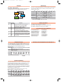
Hexadecimal rotary switches, service and I/O LEDs
Configuring the Output Channels
Negative screw-driver
0.4 x 2.5 mm
Top view
•
Hi
Lo
ide
nt s
Fro
Service Status
LEDs
ON
RUN Blinking
Single flash
OFF
ON
Single flash
ERR Double flash
Triple flash
OFF
ON
ST Blinking
Single flash
OFF
PWR ON
OFF
•
•
•
Meaning
The Output functional block diagram is consistent with the standard profile
CiA DS401 [2].
Operational
Pre-operational (CANopen)
STOPPED
Device in RESET state
BUS OFF
Warning limit reached
Error Control Event
Sync Error (CANopen)
No error. Device working
DIAG Error
INIT and DIAG running
Baud rate setting
Module OK and ready
Module Power Supply ON
Module Power Supply OFF
Index 6200h – Write Output 8-bit
I/O LEDs
Status Meaning
OUT 1...4 ON
Output active
OFF Output inactive
•
This object writes a group of 4 outputs:
1 = output active,
1 = output not active.
The output signalling from a CAN message is processed first.
Two preproces items are performed:
• Polarisation Index 6202h – Polarity Output 8-bit:
This object defines the polarity of 4 output lines.
Output polarity can be inverted individually.
1 = output inverted;
0 = output not inverted.
If the object is not supported, the device behaves according to the
default value.
• Masking Index 6208h – Filter Mask Output 8-bit
This object defines an additional output filter mask configurable for 4 outputs.
1 = output is set to the received output value
0 = do not care, the received output value is neglected for the corresponding output channel and the old output value is kept.
If the object is not supported, the device behaves according to the default value.
Error mode
Bit Rate and Node ID configuration
Bit rate
Lo switch
1
2
3
4
5
6*
7
8
Node ID
Baud rate
kbps
20
50
100
125
250
500
800
1000
Bus length
m
2500
1000
500
500
250
100
50
25
Hi
Lo
Valid ID Node
switch switch
0
1
01h (address 1)
0
2
02h (address 2)
7
F
7Fh (address 127D) *
Notes: * Default value
In error mode, the outputs behave according to the following two entries:
Index 6206h – Error Mode Output 8-bit:
This object indicates, whether an output is set to a pre-defined error value
(see 6207h object) in the event of an internal device failure or of a 'Stop
Remote Node' status.
1 = output value takes the pre-defined condition specified in object 6207h
0 = output value is kept if an error occurs
Index 6207h – Error Value Output 8-bit:
On condition that the corresponding Error Mode is active, device failures set
the outputs to the value configured by this object.
0 = Output is set to ‘0’ in case of fault, if object 6206h is enabled
1 = Output is set to ‘1’ in case of fault, if object 6206h is enabled
Procedure for Node ID and Bit Rate configuration
The HI and LO hexadecimal rotary swithches set the module’s Bit Rate and CAN Node ID.
During the configuration, the module must be off line and the CAN bus must be physically
disconnected.
To configure the module, follow the procedure:
1 Turn the Power OFF
2 Set the HI switch to “F”
3 Select the desired Bit Rate value by setting the LO switch following the table
(e.g. “8” for 1 Mbps)
4 Turn the Power ON
5 Shift the HI switch to “E” (all the module service LEDs should flash)
6 Turn the Power OFF. Now configure Node ID
7 Set the HI and LO switches to the desired valid Node ID following the table
8 Turn the Power ON.
Alternatively, at step 7 set the value 00h. Then, at the next Power ON, the last valid stored
value will be resumed as Node ID.
Default values:
Bit Rate = 500 kbps, Node ID = 127D
Proprietary output functions
In addition to the expected functions, the module provides a proprietary output
function option. Output/option combinations are fixed, and determined by the
value of the entry in the table below:
Index 2003h – Output options
Value
0
1
2
3
4
Allowed options
No option
Pulse on channel 1
Pulse on channel 2
Pulse on channel 3
Pulse on channel 4
• Generation of a single pulse of programmable width
Index 200Bh – Output Pulse Value:
Assigns the value of the duration of the pulse within a range from 5ms to
65535ms, in 5ms steps. Please note that the Output Pulse Value unit is 1 ms.
Index 200Dh – Start Stop Mode:
In RUN mode, this entry determines the trigger of the pulse. It should be noted
that the pulse function is not subject to polarity and filter mask. The generated
pulse consists of a Low-to-High edge and, at the end of programmed width, of
an High-to-Low edge:
bit 0 Start (1) ch. 1 … bit 3 Start (1) ch. 4
Please note that bits 0...3 are automatically reset by the device, i.e. they are
ready for any subsequent pulse.
‘
‘
Unused bits
bit 7 bit 6 bit 5 bit 4 bit 3 bit 2 bit 1 bit 0
Ch. 4 Ch. 3 Ch. 2 Ch. 1
0 = Stop
1 = Start