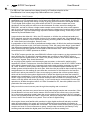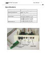
1
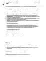
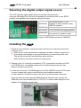
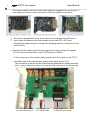
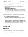
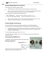
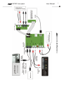
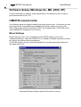
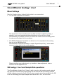
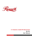
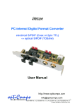
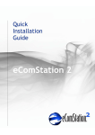
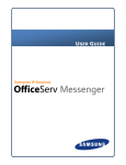
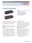
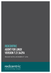
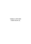
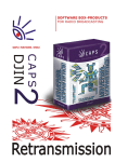
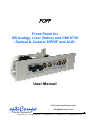
POFP
Front-Panel for
SB Audigy, Live! (Value) and CMI 8738
- Optical & Coaxial S/PDIF and AUX -
User Manual
optiCompo
ELECTRONICS
http://www.opticompo.com
[email protected]
4/25/1999 Ver. 1.0, 8/25/1999 Ver. 1.1, 1/5/2000 Ver. 1.2, 3/3/2000 Ver. 1.3, 08/20/2003 Ver 2.0
POFP S/PDIF front panel
2
User Manual
Thank you for purchasing optiCompo’s POFP (nice-Priced Optical Front Panel).
Please read the following installation procedure carefully and you will enjoy a wide
variety of S/PDIF recording options with your sound card.
Some features your POFP has to offer:
Interconnectivity - Using the POFP you can finally connect your S/PDIF audio
devices to your SoundBlaster Audigy / Live! or even a CMI8738 sound card.
• Independence - You can interconnect S/PDIF audio devices independent of their
output type - coaxial or optical jack.
• Comfort – Never again search the SPDIF or AUX connectors at the back of your
computer, crouching on the ground or the table.
• Service - If you have problems with your POFP, please check our homepage for
usefull hints and solutions:
•
http://www.opticompo.com/
Before contacting optiCompo, try to solve the problem by reading this User
Manual or the manuals and help files for the other used devices and software.
If these manuals leave any questions, we provide e-mail support at
[email protected]
So than: Just enjoy the digital world of music.
Your optiCompo team
Warning
Do not eat or pulverize any of the components of the POFP, because some
components contain toxic material!
• We are not liable for any damages caused by improper use of the POFP or it’s
components!
•
********************
Information in this manual is subject to change without notice.
Trademark Acknowledgement:
All trademarks referred herein are the property of their respective owners.
POFP S/PDIF front panel
User Manual
3
Selecting the digital output signal source
The POFP uses the digital signals as the sound card interfaces them.
Using the SB Audigy/Live! you have the possibility to select the front or rear SPDIF
channel to be passed to the output by setting the jumper.
SPDIFO#0
SPDIFO#1
SPDIFO#2
SPDIFO#3
front stereo channel, LF+RF
(signal for 2 and 4 speaker mode);
CMI8738 standard
center and subwoofer channel
mix of front and rear stereo channel
rear stereo channel, LR+RR
(only active in 4 speaker mode)
Default is SPDIFO#0 (use also for CMI8738).
Installing the POFP
1. Switch off your computer, unplug the power cord form the outlet and remove the
computer cover.
Make sure to avoid electrostatical chargings (caused by clothes, carpets etc.)
by touching a metal plate on you system before you remove the power cord.
This will ground yourself and discharge static electricity.
!
Static electricity can destroy electronic components.
2. Choose a free 5¼” drive bay to install the POFP; a good place is below your DVD
or CD-ROM drive, so dangling cables will not restrict access to the drive tray.
Remove the bay’s front cover.
3. Locate the sound card. The SBAudigy/Live! and the CMI8738 cards are PCI cards.
In tower casings this usually means that they are installed upside down.
In most cases you will have to remove the card to reach the used connectors.
Up to now there are two supported SBAudigy/Live! extension pin-outs plus the
CMI8738 sound card standard pin-out. The POFP ‘s module cable has got a multiadapter for the different sound cards.
4
POFP S/PDIF front panel
User Manual
The following pictures show how the small adapter is plugged to the sound card. In
most cases you have to remove the card to reach the used pin-connectors.
!
During the (re)installation of the sound card you should take care that there is
some space left between the multi-adapter and the next PCI / AGP card.
Although the adapter’s back is coated with insulating material you should not risk
a short circuit.
4. Pass the following cable ends from the inside of the casing through the opened
5¼” drive bay to connect them to the POFP before you install it:
♦ 14-pin connector of the module cable (connect it to the X1 port of your POFP )
♦ the black end of the included grey analog audio cable; plug it to X4.
The orientation of the red and the white lead will swap the two analog channels
(left ↔ right); connect the other end to the AUX-IN connector of the sound card.
AUX-IN connector
(to sound card analog in)
power supply via
incl. splitter cable
to SB Audigy / Live!
or CMI8738 sound card
POFP S/PDIF front panel
User Manual
5
♦ the smaller end of the included power splitter cable (Y cable), which has been
connected to the your computer’s power supply unit inside the casing; plug it to
the X3 connector of the POFP .
♦ (optional) the grey 14-pin optiCompo ribbon cable (if you like to connect an
additional digital extension module like a POAB or POCAB); plug it to the X2
connector of the POFP)
☞
Optional Digital Extension via the POFP
A second digital i/o module (e.g. a POAB or POCAB) can be connected via the
POFP ‘s 14-pin port X2; all digital signals will also be forwarded to the second module.
This is especially usefull for permanent signal connections, which can now be cabled on
the back of your computer (without the cables hanging in front of your feet or on your
desk all the time). Simply ask for the free connection cable when you purchase an
additional module.
5. Slide the POFP into the vacant 5¼” drive bay and screw it tight to the bay’s sides.
6. Finally make sure that all connections and screws are tight, close the computer
cover, plug in the power cord and switch on your computer.
☞
After the power-on there will be an immediate signal at SPDIF-OUT. Check this by
verifying that the optical output emits red light (remove the protective cap).
This means the hardware is installed correctly, bravo!
!
If the optical output does not emit light after power-on, switch off the computer
immediately. Please check the cable connections inside the computer once more.
There is a green power LED on top of the POFP, which may give you a hint: if it does
not light while the computer is running, the power supply is not connected.
Using the POFP
Analog AUX-IN
These connetors are determined for analog (stereo-)devices like tape, records, CD.
Cinch connectors are widely spread. They allows to connect a lot of different audio
devices to your sound card via a simple cable.
You can controll the AUX-IN recording level with the standard software audio mixer.
POFP S/PDIF front panel
6
User Manual
Optical Digital Signal Connections
Take TOSlink (or TOSlink-to-Miniplug) cable.
☞
TOSlink cables are offered in nearly arbitrary lengths in most audio shop.
We recommend to limit the length to 10m and to avoid sharp bendings of the cable.
Otherwise the cable loses may prevent an error free transmission.
There are mainly two different types of optical plugs:
•
•
ODT (TOSlink) plug
(used by HiFi devices, MD and DAT recorders, POCAB, …)
(used by portable MD and DAT recorders, …)
3,5mm (1/8 inch) optical miniplug
☞
Please use the protective caps for the optical interfaces when they are not in use.
This prevents dust scratches etc., which lower the signal quality.
Coaxial Signal Connections
Take cinch (RCA) cable rated at 75 Ohms; usually any cinch (RCA) cable that is
good enough to carry a video signal will also be adequate for carrying a digital signal.
☞
For distances of more than 2 meters we recommend to use shielded coaxial cable for
reliable and high quality transmission (like “digital coaxial cable”, sometimes also
referred to as SPDIF cable).
The input accepts signal levels from 0.5 to ~5..Vpp.
The output delivers a voltage level of 1.6 Vpp; the signal ground is decoupled from the
computer’s ground.
Choosing the DIGITAL IN
The SELECT switch chooses the SPDIF input signal that is
passed to the sound card.
The switch positions are
Digital INPUT from
C oax
E xternal
T OSlink
“External” means to take the signal from the (optional)
digital extension that is connected on X2.
User Manual
7
Connecting peripherals to the POFP
POFP S/PDIF front panel
8
POFP S/PDIF front panel
User Manual
Software Setup (Windows 9x, ME, 2000, XP)
It can be necessary to perform some adjustments to the software mixer to reach a
good performance of the POFP.
CMI8738 sound cards
If not allready done we suggest installing the latest known driver. In this case you can
get drivers at the chip producer’s homepage http://www.cmedia.com.tw. E.g. the
Zoltrix Nightingale and the AudioExcel AV511 are equipped with a CMI-8738 sound
chip (important for finding the correct driver).
Mixer Settings
Please start the mixer. The configuration of the SPDIF interface is found at
“Advanced Settings”. Make sure SPDIF OUT is enabled. Detailed instructions should
be found in the sound card documentation.
The SPDIF signal’s volume cannot be adjusted; for recording purposes make sure
the signal level is ok.
Advanced Settings (design varies with the driver version)
POFP S/PDIF front panel
User Manual
SoundBlaster Audigy / Live!
Mixer Settings
Start the Creative mixer. It should look similar to our screenshot.
• You will find an SPDIF-IN controller.
The adjustment of the recording level is a little unusual for digital recording. I
assume, your sound signals are already digitised, so the volume is fixed.
Nevertheless you probably will have to correct the volume at the recording mixer
to make sure the signal is not overdriven.
•
The SPDIF-OUT signal should be on all the time. It is equivalent to the analog
line-out of the SBAudigy/Live!.
Nevertheless it might be necessary to check “Digital Output Only”, as the same
resource is also used for the center speaker.
Please note that every adjustment, e.g. tremble or bass adjustment, has an
influence on the digital line-out.
SB Audigy / Live! and Sample Rate questions
The Soundblaster Audigy/Live! (Value) is able to work on all popular sample rates at
the input. But note that every signal going into the card will be converted to internal
48 kHz (refering to actual drivers). So the output sample rate is fixed at 48 kHz for SB
Live! For SB Audigy the output sample rate can be set to 44.1, 48 or 96 kHz.
9
10
POFP S/PDIF front panel
User Manual
For SB Live! the reasons have been given by a Creative scientist at the
Soundblaster Live home page http://www.sblive.com: (extract)
Dave Rossum, Chief Scientist:
It’s important to remember that the Sound Blaster Live! is much more than just a wavetable
synthesizer or a CD playback device. At its heart is the EMU10K1 e‹ects engine, a powerful
DSP performing, among other things, mixing of all the various functions in the digital domain.
To mix digital audio signals, they must all be at EXACTLY the same sample rate, even
deviations of a few parts per million must be eliminated. So when we went to design the
EMU10K1, we had to choose a single master sample rate at which the mixer would operate,
and of course we had to design sample rate converters to change any incoming audio to match
this sample rate. This is the technology required to achieve digital mixing - that’s why it’s first
featured by Sound Blaster Live!.
It was obvious that either 44.1 kHz, the CD standard, or 48 kHz, the professional audio and
DVD standard, were the only possible choices for the master sample rate. We picked 48 kHz
for a variety of reasons. First, if we were processing incoming audio at nominally 48 kHz, use of
44.1 kHz would lose information. Second, even
in preparation of 44.1 kHz CDs in professional studios today, 48 kHz is the preferred standard,
with a final conversion to 44.1 kHz as the last step. Third, the nearly twice larger ”guard band”
(the difference between 20 kHz and the Nyquist frequency) of 24 kHz means virtually every
audio process and effect performs much better at 48 kHz than at 44.1 kHz. And finally, the
economical AC-97 CODEC operates at 48 kHz.
The SPDIF outputs provide the exact EMU10K1 effects engine outputs, so they operate at this
same 48 kHz rate. So why didn’t we add sample rate converter to each SPDIF output to
convert the 48 kHz signal back to 44.1 kHz? The primary reason is cost. Since these outputs
are ”master” signals, they should be treated
as very high quality and as such the sample rate converters, to be useful, would be fairly
expensive in silicon. Furthermore, since the EMU10K1 is clocked o‹ the AC-97 CODEC master
clock which is based on 48 kHz, a separate clock and crystal would be necessary to support
44.1 kHz. At least, if audio quality were important, since a standard phase locked loop or
divider system would introduce too much jitter. And since the job could be done externally fairly
straightforward, we felt making all users bear the cost burden of this feature for the few who
would use it was a poor trade-off. Also, we are trying to promote the uniform system design
which will be found in the modern digital studio in which the digital inputs bear the burden of
sample rate normalization. For those few users who for some reason seem to need a 44.1 kHz
SPDIF output, they’ll either have to purchase a sample rate converter box (Analog Devices
makes a 20 chip which will do the job nicely), or (as I would tend to recommend) convert their
operation to 48 KHz throughout and if 44.1 kHz is needed for CD, have this jobbed out at CD
production like most people do.
Why must all the sound sources pass through the sampling rate converters?
It’s not actually true that every sound source must pass through sample rate conversion. If the
Sound Blaster Live! can serve as the master 48 kHz clock for the sound source (as provided
for in the newest operating system), then the source need not be converted. But any external
source can’t possibly know our EXACT 48 kHz rate, and so its sample rate must be normalized
to ours, even if the deviation is very small. This is a fact of digital mixing.
Once again, those most familiar with practices in older digital studios will ask why we didn’t
make accommodations for supply and receiving AES black synchronization information to
eliminate the necessity of sample rate conversion. The reason is that studio synch is simply too
complex an issue for most consumers to grasp - sample rate conversion (at least by E-mu)
sounds great and makes the digital patch cord behave just like an analog one.
POFP S/PDIF front panel
User Manual
Specifications
supply current
approx. 50mA
operating voltage
5V, supplied by SB Audigy/Live!
operating temperature
approx. 5°C – 60°C
optical in/out
TOSlink, 670nm
coaxial input
cinch (RCA) connector, 0.5 .. ~ 5 Vpp
coaxial output
cinch (RCA) connector, 1.6 Vpp
sample rate, in
2,05 MBit/s (32 kHz, e.g. DSR)
2,82 MBit/s (44.1 kHz, e.g. CD)
3,07 MBit/s (48 kHz, e.g. DAT)
sample rate, out
3,07 MBit/s (48 kHz, e.g. DAT)
Digital IN
select
coaxial digital signal
(Cinch / RCA)
optical digital signal
(TOSlink)
analog AUX-IN
(Cinch / RCA)
11