1
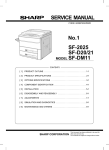
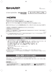
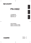
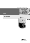
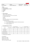
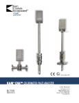
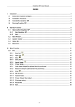
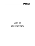
Multi Display Setup Manual
<Ver1.0>
2010/09/30
Business Solutions Equipment Division
Business Solutions Dept. SHARP Corporation
CONFIDENTIAL
About the handling of this material / Contents
CONFIDENTIAL
Contents
Handling this material
1. Precautions of installation and handling
1. Precautions of installation and handling
‐ This document is made to explain the installation know‐how of large size display for our business partners. Hence, please handle this material very carefully. 2. Mechanical installation
2. Mechanical installation
‐‐ Optional interface board
Optional interface board
‐‐ Mounting
Mounting
‐‐ Remote Control kit
Remote Control kit
- This document describes basic notes to install and use the display for long term reliable service.
3. Setting for Remote control
3. Setting for Remote control
[Warning]
This document is to explain the installation know‐
how to our business partners. Please be careful not to distribute this document or its contents to other companies, or divert (use) it towards competitors’
models. 4. Basic Display method
4. Basic Display method
5. Cable routing
5. Cable routing
‐‐ For Enlarge mode
For Enlarge mode
‐‐ For Dot by Dot configuration
For Dot by Dot configuration
‐‐ For monitor control
For monitor control
In addition, please be reminded that values and expressions on this document are subject to change without notice. 6. Calibration
6. Calibration
7. Tools for supporting installation
7. Tools for supporting installation
CONFIDENTIAL
1
Multi Display Setup Manual <Rev1.0 > September.30, 2010
CONFIDENTIAL
Precautions of installation and handling (1)
Precautions for Installation and moving
Display surface Perspective drawing of the rear side view
Grip Points
The display surface is made of glass. Please use rear handgrip or handle by the edge of the display while installing and moving. It is possible to cause damage and malfunction of display.
Please don’t apply physical pressure to the bezel such as bending or pulling on the bezel.
PN‐V601
protecting sheet like blanket
‐Do not set the PN‐V601 on a protection board smaller than itself to avoid the
contact with corner of the board.
‐ Use a protecting sheet like blanket
Protection board larger than PN‐V601
‐ Do not apply force from
the above.
Please set the PN‐V601 in the center of the protection board/protecting sheet and be careful to avoid the contact with corners of the board.
Prior to installing the PN‐V601, please refer to following items carefully in order to use PN‐V601 for long term reliable service.
Please use rear handgrip or handle by the edge of the display in installing and moving. Please don’t handle any other part of the display. The PN‐V601 is high – density product so that please pay attention not to let the edge of PV‐V601 support the entire weight load. Please take extra caution to make sure that weight load each display is supported only by the mounting system and not a neighboring display when building a multi‐screen wall. Method of interim storage of the display after taking it out from the box
‐Interim storage using the temporary stand is recommended. ‐ When you must keep the LCD surface side down without temporary stand, please prepare a protection board
larger than the display, and put a protecting sheet like blanket on it, and confirm enough there are neither debris nor a projection within the range where the LCD surface side comes in contact directly. Please execute the work
only after the greatest care is taken so that the LCD surface should not hit the edge of the protection board underneath.
CONFIDENTIAL
2
Multi Display Setup Manual <Rev1.0 > September.30, 2010
CONFIDENTIAL
Precautions of installation and handling (2)
Overall precaution and handling
‐ Do not use the information display under following conditions ;
1) Usage beyond its capability, feature/function, accuracy/precision
2) Usage that could develop into injury or life‐threatening situation under product breakdown
3) Usage that could lead to major monetary damage
We will not take any responsibility if the product was used under above conditions.
<Example>
Control of all types of safety related usage of transportation equipment (air plane, train, car, etc.), aerospace equipment, communication equipment, nuclear control equipment, medical equipment, disaster‐prevention/security equipment, all types of safety equipment, etc.
‐ We will not take any responsibility for any failure, damage, loss, etc. which arise from particular installation (high‐ceiling mounting etc.) and/or installation by non‐Sharp related parties. Prior to the installation, please examine the potential problems by the installation location and installation method, and only operate within the appropriate environment.
In case of product failure, regardless of warranty period, removal and installation expenses incurred will be the customer’s responsibility.
Repairing may take a certain time period. For that reason, arranging of a back‐up is recommended. ‐ Installation environment of the information display differs by individual cases. Please make appropriate installation by referring to this material. If you have any difficulty in making judgment about installation or have any comments/questions about the contents of this material, please ask SHARP Business Solution factory via your local Sharp sales window. Please refer the PN‐V601 Installation Guidelines for other precautions.
CONFIDENTIAL
3
Multi Display Setup Manual <Rev1.0 > September.30, 2010
CONFIDENTIAL
Mechanical installation (Optional Interface board)
Optional Interface board PN‐ZB02
■Installation Procedure
PN‐V601 has following input/output terminals.
Additional terminals such as DVI‐D input/output, Component, LAN etc.. are available by attaching the optional expansion board PN‐ZB02.
CONFIDENTIAL
4
Multi Display Setup Manual <Rev1.0 > September.30, 2010
Mechanical installation (Remote Control kit)
CONFIDENTIAL
How to attach Remote Control
All monitors can be operated using one remote controller when one of the monitors is fitted with a remote control sensor box
CONFIDENTIAL
5
Multi Display Setup Manual <Rev1.0 > September.30, 2010
Setting for Remote Control (1)
CONFIDENTIAL
Setting for Remote Control kit
CONFIDENTIAL
6
Multi Display Setup Manual <Rev1.0 > September.30, 2010
Setting for Remote Control (2)
CONFIDENTIAL
7
CONFIDENTIAL
Multi Display Setup Manual <Rev1.0 > September.30, 2010
CONFIDENTIAL
Basic display method (Enlarge or Dot by Dot)
Resolution for Enlarge mode and Dot by Dot configuration
Dot‐by‐dot mode
2304
1x3
Enlarge mode
Create contents with 2304x1366 pixels (or
16:9.5 aspect ratio under dot‐by‐dot)*
1366
The enlarge mode in this this configuration won’t work because aspect ratio will be different from original the one.
2732
2x2
Create contents with 2732x1536 pixels
(or 16:9 aspect ratio under dot‐by‐dot)*
1536
Enlarge 1920x1080
contents to 2732x1536.
4098
2x3
1536
Create contents with 4098x1536 pixels
(or 16:6 aspect ratio under dot‐by‐dot)*
The enlarge mode in this this configuration won’t work because aspect ratio will be different from original the one.
4098
3x3
Create contents with 4098x2304 pixels
(or 16:9 aspect ratio under dot‐by‐dot)*
2304
Enlarge 1920x1080
contents to 4098x2304
*: When the contents can not be created with dot‐by‐dot mode ie. moving picture.
CONFIDENTIAL
8
Multi Display Setup Manual <Rev1.0 > September.30, 2010
CONFIDENTIAL
Cable routing (for Enlarge mode)
Cable configuration for Enlarge mode
1) DVI Daisy chain
2) Other input (HDMI/RGB/Component) and DVI connection in case of more than 6 monitors. Third monitor and after
Signal Splitter
DVD/BLUE RAY Player
Please refer to the user manual for detailed connection information of the signal splitters. CONFIDENTIAL
9
Multi Display Setup Manual <Rev1.0 > September.30, 2010
CONFIDENTIAL
Enlarge mode setup
Enlarge mode setup with OSD
CONFIDENTIAL
10
Multi Display Setup Manual <Rev1.0 > September.30, 2010
Cable routing (for Dot by Dot configuration)
CONFIDENTIAL
Cabling for Dot by Dot
DVI / HDMI
DVI / HDMI
Work station
PN-V601
PN-ZB02
PN-V601
PN-ZB02
Graphic board
PN-V601
PN-ZB02
PN-V601
PN-ZB02
DVI / HDMI
DVI / HDMI
Graphic boards which have multiple out put terminals are necessary to realize dot by dot display.
Each monitor needs to be connected via DVI or HDMI to a dedicated port on the graphic cards.
Multi display setup depends on the type of graphic board and graphics driver.
Please refer to the details supplied in the graphic board manuals. CONFIDENTIAL
11
Multi Display Setup Manual <Rev1.0 > September.30, 2010
Cable routing for monitor control
Cabling (for monitor control)
Three types of connections are available.
1) Connection by RS‐232C
PNZR01(light receiving device)
(1) Control and measuring PC
CONFIDENTIAL
1. Choose RS‐232C from RS‐232C/LAN SELECT at the set up page of the all monitors in OSD menu
2. Assign a unique ID number to each monitor
3. Connect PC (1) and the first monitor with RS‐232C straight cable (do not use a null‐modem cable)
4. Make a daisy chain with RS‐232C straight cables
5. Install monitor calibration tool and the drivers for the measuring device into PC (1).
*If you use the remote control in this configuration, please set PN‐ZR01 (light‐receiving device) to the first monitor. 2) Connection by LAN
1. Choose LAN from RS‐232C/LAN SELECT at the set up of the all monitors.
2. Assign unique IP address to each monitor. (static IP or DHCP)
3. Connect PC (1) and all monitors by LAN
4. Install monitor calibration tool and the drivers for the measuring device into the PC (1)
PNZR01
(light receiving device)
*If you use the remote control in this configuration, please set PN‐ZR01 (light‐receiving device) to the first monitor. And you need to make a daisy
chain with RS‐232C straight cables and assign unique IDs as well.
(1) Control and measuring PC
3) Mixed Connection by RS‐232C and LAN
PNZR01(light receiving device)
(1) Control and measuring PC
CONFIDENTIAL
12
1. Choose LAN from RS‐232C/LAN SELECT at the set up of the first unit. 2. Select RS‐232C for 2nd monitor and each one after
3. Assign a unique ID number to each monitor
4. Connect PC (1) and the first monitor by LAN
4. Make daisy chain for all remaining monitors with RS‐232C straight cable (do not use null‐modem cables)
5. Install monitor calibration tool and the drivers for the measuring device into PC (1).
*If you use the remote control in this configuration, please set PN‐ZR01 (light‐receiving device) to the first monitor. Multi Display Setup Manual <Rev1.0 > September.30, 2010
Monitor control software setup
CONFIDENTIAL
Monitor control with calibration tool
CONFIDENTIAL
13
Multi Display Setup Manual <Rev1.0 > September.30, 2010
Monitor control software setup
CONFIDENTIAL
Monitor control with calibration tool
<TIPS>
The parameters are different depending on the particular connection
1) Connection by RS‐232C
Search Interface : All
Search daisy chained monitors: check
2) Connection by LAN
Search Interface : LAN
Search daisy chained monitors: uncheck 3) Mixed connection by LAN and RS‐232C
Search Interface : All
Search daisy chained monitors: check CONFIDENTIAL
14
Multi Display Setup Manual <Rev1.0 > September.30, 2010
Calibration tool software setup
CONFIDENTIAL
Setting Video Wall and Enlarge mode via the calibration tool
CONFIDENTIAL
15
Multi Display Setup Manual <Rev1.0 > September.30, 2010
CONFIDENTIAL
Calibration (1)
How to adjust the color
•The color can be adjusted by the image adjustment function of the display by operating remote controller or the control tool offered from our company. (Please refer to software tool SHARP Monitor Control Software. )
• Also, it can be adjusted with the color calibration tool from our company.
(Please refer to software tool Multi Display Calibration Tool). It is necessary to buy our recommended colorimeter. For the adjustment of one unit, it will take about five minutes with 6‐gradation adjustment of (our recommendation), about seven minutes with 16‐gradation, and about 10 minutes with 32‐gradation
Color Adjustment Procedures for New Installation
Need set to a specific color temperature and brightness by using the colorimeter
Adjust with the color calibration tool
color temperature and brightness are have been adjusted at factory
Can adjust
YES
Need adjust the color with
the installation environment
NO
Fine‐tunes with manual adjustment for the gamma value of the calibration tool. End of Adjustment Adjust with the image adjustment function of the display
Can adjust
CONFIDENTIAL
End of Adjustment End of Adjustment End of Adjustment * Usually, you need not use the color calibration tool .
16
Multi Display Setup Manual <Rev1.0 > September.30, 2010
CONFIDENTIAL
Calibration (2)
color adjustment procedures for difference of the color temperature and brightness between displays due to change over time
color adjustment procedures when display is replaced
Confirm the difference of color and brightness by eye between replaced display and other ones
No difference
Select a display and measure targeted color and brightness with the color calibration tool
End of Adjustment Adjust with the image adjustment function of the display
Can adjust
Can adjust all
End of Adjustment Adjust with the image adjustment function of the display
Select a display and measure targeted color and brightness with the color calibration tool
Can adjust
Adjust to the targeted color and the brightness with the color calibration tool
Adjust the replaced display to the targeted color and the brightness with the color calibration tool Can adjust
End of Adjustment Can adjust
End of Adjustment Fine‐tunes for the gamma value with manual adjustment of the calibration tool. Fine‐tunes for the gamma value with manual adjustment of the calibration tool. Can adjust
End of Adjustment for One unit
End of Adjustment CONFIDENTIAL
17
Multi Display Setup Manual <Rev1.0 > September.30, 2010
CONFIDENTIAL
Calibration (3)
How to implement calibration
CONFIDENTIAL
18
Multi Display Setup Manual <Rev1.0 > September.30, 2010
CONFIDENTIAL
Calibration (4)
How to implement calibration
CONFIDENTIAL
19
Multi Display Setup Manual <Rev1.0 > September.30, 2010
CONFIDENTIAL
Calibration (5)
How to implement calibration
CONFIDENTIAL
20
Multi Display Setup Manual <Rev1.0 > September.30, 2010
Tools for supporting installation (1)
CONFIDENTIAL
Installation tools for attachment and moving to the installation location
Installation handle
Installation eyebolt device
Interlocking pipe
Please take care not to add pressure to
parts other than the ones marked with a
heavy line in the diagram during
installation and maintenance.
If pressure is added to other parts, the
display itself may be distorted or damaged.
Support PN-V601 by holding both corners.
CONFIDENTIAL
21
Multi Display Setup Manual <Rev1.0 > September.30, 2010
Tools for supporting installation (2)
CONFIDENTIAL
We will provide following service parts for installation (they are subject to fees)
Name (temporary)
Use
Image
Installation handle
(UKOG1005MPZZ)
‐ For lifting the PN‐V601 up to a high location
This device is inserted into holes on top of PN‐V601 and enable lifting the PN‐V601 up to a high location during installation.
2 pieces of this device are necessary per one PN‐V601.
This installation handle is for improving efficiency of installation. Please use it if necessary.
Installation eyebolt device
(UKOG1006MPZZ)
‐ For a crane to lift the PN‐V601 up to a high location.
This device is inserted into holes on top of PN‐V601 and enable lifting the PN‐V601 up by crane.
2 pieces of this device are necessary per one PN‐V601.
This installation eyebolt device is for improving the efficiency of installation. Please use it if necessary.
Interlocking pipe
(UKOG‐1007MPZZ)
‐For making it easy to install PN‐V601
It can reduce gap between the top‐to‐bottom of the PN‐V601 and interlock each panel from both on the top and bottom of the PN‐V601 when installing with a stand etc. This pipe can prevent PN‐V601 from having excessive weight load from above and underneath. Please use this interlocking pipe for improving the accuracy when adjusting the vertical position of displays if necessary. It is not required for installation. 2 pieces of this pipe are necessary per one PN‐V601.
* if you need above tools, please contact delivery agent or our sales reps.
CONFIDENTIAL
22
Multi Display Setup Manual <Rev1.0 > September.30, 2010
Tools for supporting installation (3)
CONFIDENTIAL
We will provide following service parts for installation (they are subject to fees)
Name (temporary)
Use
Image
Protection cover for the corner of display
(UKOG1008MPZZ)
‐‐ Reduce shock while moving and installing
These covers are attached on the two bottom corners of PN‐V601 to protect PN‐V601 from shock.
It is easy to remove the cover.
‐ 2 units of this cover are necessary per one PN‐V601. Protection spacer (for landscape)
‐Protection of display
Insert this spacer between the PN‐V601 while installing the neighboring PN‐V601s. (thickness: 1 mm)
This tool is used to avoid damage of the bezel at the time of installation and the position adjustment of the display.
‐Please take care that the sheet does not extend out of display side.
Gel Sheet
Thickness: 1.0mm
‐Protection of display
Insert this spacer between the PN‐V601 while installing neighboring PN‐V601’s. (thickness: 0.5 mm)
This tool is used to avoid damage of the bezel at the installation and the position adjustment of the display.
‐Please take care that the sheet does not extend out of the display side
Gel Sheet
Thickness: 0.5mm
Protection spacer (for Portrait)
* if you need above tools, please contact delivery agent or our sales reps.
CONFIDENTIAL
23
Multi Display Setup Manual <Rev1.0 > September.30, 2010
CONFIDENTIAL
Tools for supporting installation (4)
We will provide following service parts for installation (they are subject to fees)
Name (temporary)
Use
Image
Installation spacer device
(UKOG1011MPZZ)
‐ Insert this spacer between the PN‐V601 while installing the neighboring PN‐V601s so the units do not touch. And after installation is finished, remove this spacer
device.
Temporary stand
(UKOG1004MPZZ)
Temporary stand
‐This stand is for fixing PN‐V601 temporarily to check operation and perform settings before installation.
2 pieces of this stand are necessary per one PN‐V601.
Supply cable for 200 volts
(QACCJA104WJPZ)
Supply cable for 200 volts
‐Supply cable for 100 (120V) volts is enclosed in PN‐V601 for Japan (US) model.
If PN‐V601 is used with with 200 volt environment , power supply cable for 200 volts is necessary.
* if you need above tools, please contact delivery agent or our sales reps.
CONFIDENTIAL
24
Multi Display Setup Manual <Rev1.0 > September.30, 2010
Tools for supporting installation (5)
Tentative name
Bezel sheet
Use
CONFIDENTIAL
Figure Image
‐Please attach bezel sheets on the 4 sides of the PN‐V601 to cover the white areas on the sides of the display.
‐4 bezel sheets is necessary per one PN‐V601(for top / bottom / right / left side). ‐In order to study the detail on how to attach bezel sheet, please refer to the introduction material enclosed in PN‐V601 package (one sheet).
‐Please note that this sheet can not be put on after setting
up the multi‐screen display.
Bezel sheet
(Packing image)
Bezel sheet
(Attached on PN‐V601)
* Bezel sheet is enclosed in PN‐V601 package
* if you need above tools, please contact delivery agent or our sales reps.
CONFIDENTIAL
25
Multi Display Setup Manual <Rev1.0 > September.30, 2010