1
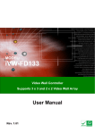
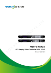
iVW-UD322 Video Wall Controller iVW-UD322 / iVW-UD322F Video Wall Controller Supports 2 x 2, 2 x 1, 3 x 1, 1 x 3, 4 x 1 & 1 x 4 Video Wall Array User Manual Rev. 1.01 i iVW-UD322 Video Wall Controller Notice Thank you for choosing iNDS products! This user manual provides detailed instructions of using the iVW-UD322 Video Wall Controller. Please read carefully and start to enjoy the powerful functions of the video wall controller! • iVW-UD322 is hereafter referred to as the iVW-UD322 Video Wall Controller. • This manual provides the description of all the functions of iVW-UD322. Legal Notices All the features, functionality, and other product specifications are subject to change without prior notice or obligation. Information contained herein is subject to change without notice. iNDS and the iNDS logo are trademarks of iNDS Technology, Inc. All other brands and product names referred to are trademarks of their respective holders. Further, the ® or ™ symbols are not used in the text. DISCLAIMER In no event shall the liability of iNDS Technology, Inc. (iNDS) exceed the price paid for the product from direct, indirect, special, incidental, or consequential software, or its documentation. iNDS makes no warranty or representation, expressed, implied, or statutory, with respect to its products or the contents or use of this documentation and all accompanying software, and specifically disclaims its quality, performance, merchantability, or fitness for any particular purpose. iNDS reserves the right to revise or update its products, software, or documentation without obligation to notify any individual or entity. Back up the system periodically to avoid any potential data loss. iNDS disclaims any responsibility of all sorts of data loss or recovery. ii iVW-UD322 Video Wall Controller Table of Contents NOTICE ............................................................................................................................ II TABLE OF CONTENTS ................................................................................................ III LIST OF FIGURES ..........................................................................................................V LIST OF TABLES ......................................................................................................... VII 1 INTRODUCTION.......................................................................................................... 1 1.1 INTRODUCTION........................................................................................................... 2 1.2 FEATURES ................................................................................................................... 2 1.3 EXTERNAL INTERFACES, SWITCHES AND LEDS .......................................................... 3 1.3.1 Front Panel ........................................................................................................ 3 1.3.2 Rear Panel ......................................................................................................... 3 1.4 TECHNICAL SPECIFICATIONS ...................................................................................... 4 1.5 DIMENSIONS ............................................................................................................... 5 2 PACKING LIST ............................................................................................................. 6 3 INSTALLATION ........................................................................................................... 8 3.1 REQUIREMENTS .......................................................................................................... 9 3.1.1 Video Card ......................................................................................................... 9 3.1.2 Monitors ............................................................................................................. 9 3.1.3 Cables ................................................................................................................ 9 3.2 ARRAY SETUP OPTIONS ............................................................................................ 10 3.2.1 2 x 2 (Landscape) ............................................................................................. 10 3.2.2 2 x 2 (Portrait) ................................................................................................. 10 3.2.3 2 x 1 (Landscape) .............................................................................................. 11 3.2.4 2 x 1 (Portrait) .................................................................................................. 11 3.2.5 3 x 1 (Landscape) ............................................................................................. 12 3.2.6 3 x 1 (Portrait) ................................................................................................. 12 3.2.7 4 x 1 (Landscape) ............................................................................................. 13 3.2.8 4 x 1 (Portrait) ................................................................................................. 13 iii iVW-UD322 Video Wall Controller 3.2.9 1 x 3 (Landscape) ............................................................................................. 14 3.2.10 1 x 3 (Portrait) ............................................................................................... 14 3.2.11 1 x 4 (Landscape) ........................................................................................... 15 3.2.12 1 x 4 (Portrait) ............................................................................................... 15 3.3 INSTALL MONITORS .................................................................................................. 16 3.4 MOUNT THE VIDEO WALL CONTROLLER .................................................................... 16 3.5 CONNECT CABLES .................................................................................................... 17 3.5.1 Connect the DVI Cables................................................................................... 17 3.5.2 Connect iVW-UD322 to the Power Supply ...................................................... 17 3.6 RESOLUTION AND DISPLAY MODE CHARTS .............................................................. 18 3.7 SETTING VIDEO WALL CONTROLLER AND GRAPHICS CARD RESOLUTION................ 20 3.7.1 Set the graphic resolution manually ................................................................ 20 3.8 BEZEL COMPENSATION ............................................................................................. 22 4 OSD FUNCTIONS ....................................................................................................... 23 4.1 ON SCREEN DISPLAY (OSD) .................................................................................... 24 4.1.1 OSD Buttons..................................................................................................... 24 4.1.2 OSD Menu ........................................................................................................ 24 4.1.3 Remote Control (Optional) .............................................................................. 34 4.1.4 Reset to Factory Default Settings .................................................................... 34 4.2 SMARTOSD SOFTWARE ............................................................................................ 35 4.2.1 Installing SmartOSD ........................................................................................ 35 4.2.2 Using SmartOSD Software............................................................................... 41 5 TROUBLESHOOTING .............................................................................................. 48 5.1 TROUBLESHOOTING.................................................................................................. 48 5.1.1 No Image on One Monitor ............................................................................... 48 5.1.2 No Image on Two or More Monitors................................................................ 49 5.1.3 No Image on Any Monitor ................................................................................ 49 iv iVW-UD322 Video Wall Controller List of Figures Figure 1-1: iVW-UD322 overview...................................................................................................2 Figure 1-2: iVW-UD322 Front Panel ..............................................................................................3 Figure 1-3: iVW-UD322 Rear Panel ...............................................................................................3 Figure 1-4: iVW-UD322 Dimensions..............................................................................................5 Figure 3-1: Mounting Brackets ....................................................................................................16 Figure 3-2: iVW-UD322 Video Input ............................................................................................17 Figure 3-3: Display Modes ...........................................................................................................18 Figure 3–4: Video Card Output Resolution ................................................................................21 Figure 3–5: Enable Display Modes not supported by the monitor ..........................................22 Figure 4-1: OSD Buttons ..............................................................................................................24 Figure 4-2: Mask Control .............................................................................................................26 Figure 4-3: Link Control ...............................................................................................................27 Figure 4-4: Slave Mask Setting ....................................................................................................28 Figure 4-5: Settings ......................................................................................................................29 Figure 4-6: Warning ......................................................................................................................30 Figure 4-7: Information ................................................................................................................30 Figure 4-8: Sync and Power ........................................................................................................31 Figure 4-9: Firmware Information ...............................................................................................32 Figure 4-10: Serial Number ..........................................................................................................33 Figure 4-11: Remote Control .......................................................................................................34 Figure 4-12: Reset to Factory Defaults .......................................................................................34 Figure 4-13: SmartOSD installation program ............................................................................35 Figure 4-14: SmartOSD Welcome Screen ..................................................................................36 Figure 4-15: SmartOSD Installation Directory ...........................................................................37 Figure 4-16: SmartOSD Ready to Install ....................................................................................37 Figure 4-17: SmartOSD Additional Tasks ..................................................................................38 Figure 4-18: SmartOSD Ready to Install ....................................................................................39 Figure 4-19: SmartOSD Installing ...............................................................................................39 Figure 4-20: SmartOSD Installation Complete ...........................................................................40 Figure 4-21: SmartOSD PC Setting .............................................................................................42 v iVW-UD322 Video Wall Controller Figure 4-22: SmartOSD Master Control Panel ...........................................................................43 Figure 4-23: SmartOSD Slave Control Panel .............................................................................45 Figure 4-24: SmartOSD Master Data ...........................................................................................47 vi iVW-UD322 Video Wall Controller List of Tables Table 1-1: Technical Specifications ..............................................................................................4 Table 2-1: Package List Contents .................................................................................................7 Table 4-1: OSD Menu Structure ...................................................................................................25 Table 4-2: SmartOSD Menu Structure ........................................................................................41 vii iVW-UD322 Video Wall Controller Chapter 1 1 Introduction 1 iVW-UD322 Video Wall Controller 1.1 Introduction Figure 1-1: iVW-UD322 overview The iVW-UD322 video wall controller is the turnkey solution on extending single display to an array of monitors. A huge display area can be composed by several comodity or prefessonial monitors with lower cost and rich layouts comparing with a single large monitor. iVW-UD322 also provides pixel to pixel mapped ultra high resolution for the applications like surveillence, medical, wayfinding and digital signage. 1.2 Features The features of the iVW-UD322 include: Dual-link DVI video input Four DVI video outputs Support for up to 1920 x 1200 output resolution (per monitor) Non-scaling, pixel to pixel mapping between input source and the outputs. Support landscape and portrait on monitor orientation. Bezel control compensates for gaps between monitors 2 iVW-UD322 Video Wall Controller 1.3 External Interfaces, Switches and LEDs 1.3.1 Front Panel The front panel has the following buttons and indicators: Power LED indicator Video output LED indicator Video input LED indicators OSD buttons Infrared sensor Figure 1-2: iVW-UD322 Front Panel 1.3.2 Rear Panel The rear panel has the following connectors, switches and indicators: 4 x DVI output 1 x DVI input 1 x Power input 1 x Power switch 1 x RS-232 port 1 x Optical fiber input / output (iVW-UD322F only, for frame sync between multiple iVW-UD322F controllers) Figure 1-3: iVW-UD322 Rear Panel 3 iVW-UD322 Video Wall Controller 1.4 Technical Specifications The features of iVW-UD322 are listed in Table 1-1. See Chapter 2 for details. Specification Description Main Features 1. Multiple display modes 2. On Screen Display (OSD) to adjust settings 3. Unique Bezel compensation Technology (GeniMask) 4. Remote control (optional) Inputs 1 x Dual-link DVI-D Outputs 4 x Single-link DVI-D Dimensions (W x D x H) 230 mm x 180 mm x 47 mm Mechanical Fanless design Input Resolution See Section 3.6: Resolution and Display Mode Charts Output Resolution See Section 3.6: Resolution and Display Mode Charts Power Adapter Input 100 VAC to 240 VAC / 50 Hz to 60 Hz Power Adapter Output 12V, 3.33A, 40W Safety and Emission CE, FCC Operating Temperature 0ºC – 40ºC Power Consumption 18 W Table 1-1: Technical Specifications 4 iVW-UD322 Video Wall Controller 1.5 Dimensions The dimensions are shown below. Figure 1-4: iVW-UD322 Dimensions 5 iVW-UD322 Video Wall Controller Chapter 2 2 Packing List 2.1 Packing List NOTE: If any item in the package is missing, stop the installation and contact the sales representative by emailing [email protected].. Every iVW-UD322 is shipped with the following components: No. Description 1 iVW-UD322 Video Wall Controller 2 Power cord 3 Power adapter Image 6 iVW-UD322 Video Wall Controller No. Description 4 Remote control (Optional) 5 Mounting brackets 6 Screw kit for mounting bracket 7 User manual CD 8 Dual-link DVI cable x 1 Image Table 2-1: Package List Contents 7 iVW-UD322 Video Wall Controller Chapter 3 3 Installation 8 iVW-UD322 Video Wall Controller 3.1 Requirements NOTE: We strongly recommand to follow the requirements below for the best output quality on iVW-UD322. Before the installation, make sure the minimum hardware requirements can be fullfilled.. 3.1.1 Video Card The video card output resolution must compliant the input requirements for the corresponding output mode. The following graphics controllers was verified to support all the required output resolution: Nvidia GeForce GTS 400 series or higher Nvidia GeForce GTX 400 series or higher Nvidia Quadro FX series Other graphics controllers not listed above might still work if the combinations listed in Section 3.6. can be supported. 3.1.2 Monitors The monitors attached to the video wall controller must support the specified output resolution. The exact requirement depend on the installation refer to Section 3.6 for the requirements. For best display quality for the output video array, the connected monitors should be the same model. 3.1.3 Cables One dual-link DVI cable is included with iVW-UD322. The following cables are required for the installation: Video card to video wall controller: one dual-link DVI cable (included) 9 iVW-UD322 Video Wall Controller Video wall controller to monitors: each monitor requires a single-link or dual-link DVI cable (exact number depends on setup,) 3.2 Array Setup Options The iVW-UD322 videl wall controller supports array setup as shown in the subsections below. Both landscape and portrait installations are supported. Please refer to the following charts. 3.2.1 2 x 2 (Landscape) To setup four monitors as a 2 by 2 array in landscape mode, connect the monitors as shown below. 3.2.2 2 x 2 (Portrait) To setup four monitors as a 2 by 2 array in portrait mode (90° clockwise) , connect the monitors as shown below. 10 iVW-UD322 Video Wall Controller 3.2.3 2 x 1 (Landscape) To setup two monitors in landscape mode, connect the monitors as shown below. 3.2.4 2 x 1 (Portrait) To setup two monitors in portrait mode (90° clockwise), connect the monitors as shown below. 11 iVW-UD322 Video Wall Controller 3.2.5 3 x 1 (Landscape) To setup three monitors in landscape mode, connect the monitors as shown below. 3.2.6 3 x 1 (Portrait) To setup three monitors in portrait mode (90° clockwise), connect the monitors as shown below. 12 iVW-UD322 Video Wall Controller 3.2.7 4 x 1 (Landscape) To setup four monitors in landscape mode, connect the monitors as shown below. 3.2.8 4 x 1 (Portrait) To setup four monitors in portrait mode (90° clockwise), connect the monitors as shown below. 13 iVW-UD322 Video Wall Controller 3.2.9 1 x 3 (Landscape) To setup three monitors in landscape mode, connect the monitors as shown below. 3.2.10 1 x 3 (Portrait) To setup three monitors in portrait mode (90° clockwise), connect the monitors as shown below. 14 iVW-UD322 Video Wall Controller 3.2.11 1 x 4 (Landscape) To setup four monitors in landscape mode, connect the monitors as shown below. 3.2.12 1 x 4 (Portrait) To setup four monitors in portrait mode (90° clockwise), connect the monitors as shown below. 15 iVW-UD322 Video Wall Controller 3.3 Install Monitors The monitors should be installed in one of the configurations shown in the previous section. Recommended installation procedures are as below: Use all the same monitors * Recommand to use monitors without control buttons around side of the bezel, otherwise the buttons will be blocked by other monitors Minimize gaps between monitors for the best image Maintain consistent horizontal and vertical gaps between monitors 3.4 Mount the video wall controller The iVW-UD322 video wall controller must be placed on a table, desk or other firm surfaces. Optionally, the video wall controller can be mounted by using the included mounting brackets. The installation location must be: Out of direct sunlight Without anything on top of it On a firm surface Away from moisture and wet environment Figure 3-1: Mounting Brackets 16 iVW-UD322 Video Wall Controller 3.5 Connect Cables The cables that need to be attached are listed below: Video input cable (Dual-link DVI) – from the video source or computer to the video wall controller Video output cables – attached to the monitors. Make sure the cables are connected to the correct monitors securely (refer to Section 3.2: Array Setup Options). Power cable – from the power adapter 3.5.1 Connect the DVI Cables To connect the DVI cables to the video wall controller, follow the instructions below. Step 1: Attach the included DVI cable to the DVI input of the video wall controller and the DVI output of the video source (usually the graphic card of computer). Step 2: Attach the DVI cables from the video wall controller DVI outputs to the monitors. Attach the DVI cables as shown in Section 3.2: Array Setup Options. Step 2: Figure 3-2: iVW-UD322 Video Input 3.5.2 Connect iVW-UD322 to the Power Supply Connect the included AC power adaptor into an AC outlet then connect the DC plug to the video wall controller. Turn on iVW-UD322 by using the power switch located at the back panel. 17 iVW-UD322 Video Wall Controller 3.6 Resolution and Display Mode Charts The display modes are automatically set according to the input resolution. The input and output resolutions for iVW-UD322 are shown in the following subsections. Figure 3-3: Display Modes Mode 1x1 2x1 Input Output Vertical Resolution Resolution Hz 1024x768 1024x768 60 4:3 2560x1024 1280x1024 60 5:4 3840x1080 1920x1080 60 16:9 3840x1200 1920x1200 60 16:10 2048x1536 1024x768 60 4:3 2560x2048 1280x1024 60 5:4 2560x1440 1280x720 60 16:9 2560x1600 1280x800 60 16:10 2720x1536 1360x768 60 16:9 3840x2880 1920x1440 60 4:3 Monitor Ratio / Notes 2x2 18 iVW-UD322 Video Wall Controller Mode Input Output Vertical Resolution Resolution Hz 3840x2160 1920x1080 60 16:9 3840x2400 1920x1200 60 16:10 2560x1920 1280x960 60 1280x960 640x480 60 3392x1920 1696x960 60 1696x960 848x480 60 2732x1536 1366x768 60 16:9 3392x480 848x480 60 16:9 3200x600 800x600 60 4:3 3840x600 960x600 60 16:10 4094x768 1024x768 60 4:3 1024x3072 1024x768 60 4:3 1280x3200 1280x800 60 16:10 1280x4095 1280x1024 60 5:4 1360x3072 1360x768 60 16:9 1366x3072 1366x768 60 16:9 3072x768 1024x768 60 4:3 3840x800 1280x800 60 16:10 3840x1024 1280x1024 60 5:4 4080x768 1360x768 60 16:9 1024x2304 1024x768 60 4:3 1280x2400 1280x800 60 16:10 Monitor Ratio / Notes As the master of other iVW-UD322s when casecading As the slave controller when casecading As the master of other iVW-UD322s when casecading As the slave controller when casecading 4x1 1x4 3x1 1x3 19 iVW-UD322 Video Wall Controller Mode Input Output Vertical Resolution Resolution Hz 1280x3072 1280x1024 60 5:4 1360x2304 1360x768 60 16:9 1366x2304 1366x768 60 16:9 Monitor Ratio / Notes 3.7 Setting Video Wall Controller and Graphics Card Resolution To setup the resolution on the graphics card and on the video wall controller, follow the instructions below. Step 3: Turn on the video wall controller. Step 4: Turn on the computer. Step 5: The computer will automatically detect the video wall controller as a display. Step 6: Set the required output resolution on the video wall controller Step 7: Check the input resolution on the video wall controller and look up in the setting table above. If the resolution is not listed, then correct the settings manually to the nearest mode in the display mode list as shown in the section below. S te p 0 : 3.7.1 Set the graphic resolution manually If the graphics card settings do not adjust automatically after the video wall controller is connected, follow these steps to fix the problem. Step 1: Restart the computer. Some graphics cards don't support the correct detection on the video wall controller connected at runtime and a system restart is required. Step 2: After restarting, check the output resolution. Right-click on the desktop and select "Properties". 20 iVW-UD322 Video Wall Controller Figure 3–4: Video Card Output Resolution Step 3: Select the "Advanced" video card setting. Step 4: Uncheck "Hide modes that this monitor cannot display". S te p 0 : 21 iVW-UD322 Video Wall Controller Figure 3–5: Enable Display Modes not supported by the monitor 3.8 Bezel Compensation The bezel compensation setting compensates for the gaps between monitors in the video wall array. The bezel compensation sizes the image slightly larger than the visible screen to make the images on adjacent monitor line-up correctly. The bezel compensation values can be set by using OSD menu (Section 4.1) or the SmartOSD software (Section 4.2) . 22 iVW-UD322 Video Wall Controller Chapter 4 4 OSD Functions 23 iVW-UD322 Video Wall Controller 4.1 On Screen Display (OSD) The OSD menu functions are described below. 4.1.1 OSD Buttons Customer can control iVW-UD322 through the OSD by operating the buttons on front panel as below Figure 4-1: OSD Buttons Menu. Enters the OSD, selects items and sets the new values entered. Left. Moves the selection left. Right. Moves the selection right. Up. Moves the selection up. Down. Moves the selection down. Enter. No function for this model. 4.1.2 OSD Menu The subsections below cover the layout and use of the OSD. The table below shows the OSD menu structure. Menu Options Description Mask Control MASK Toggles the mask function ON and OFF X Set the horizontal mask value Y Set the vertical mask value LINK Enable/disable the link between the master Link Control video wall controller mask value and the slave controller's value 24 iVW-UD322 Video Wall Controller Menu Options Description Slave Mask Setting DVI DVI 1-4: Update linked slave controllers’ (Note: These settings settings can only be changed DVI x: Update setting for an individual slave while Link function is controller when link is off. turned off and Scan function is turned on) Settings Warning Information Sync and Power X Set the horizontal mask value Y Set the vertical mask value OUT Set the output resolution MODE Set the output mode Change Warns that the output resolution on the Setting video source must be changed. OUT Shows the output resolution IN Shows the input resolution No SYNC Time to enter stand-by mode when there is Pwr Off no video signal input SYNC Enable/disable the synchronization between video wall controllers with fiber optical cable. (iVW-UD322F only) SCAN Toggles the scan function between the master video wall controller and the slave video wall controllers Version Information Model information FPGA Version number of one FPGA chip CPLD Version number of the CPLD chip FW Firmware version number Name Displays the model name SN Displays the serial number Table 4-1: OSD Menu Structure 25 iVW-UD322 Video Wall Controller 4.1.2.1 Mask Control Mask control compensates for the gaps between monitors by displaying the images slightly larger than the visible screen. Figure 4-2: Mask Control Mask Enable / disable the mask function. With the mask function on, the image is adjusted to compensate for gaps between monitors in the video wall. Available selections: Off On Right Left Top Buttom X Adjusts the value of compensation from left to right. Y Adjusts the value of compensation from top to bottom. 26 iVW-UD322 Video Wall Controller 4.1.2.2 Link Control Link control allows the master controller to automatically adjust the mask settings of the attached slave controllers. Figure 4-3: Link Control LINK This setting toggles the link setting on and off. Off: When adjusting the mask of the master video wall controller, the mask of the slave video wall controllers will not be adjusted On: When adjusting the mask of the master video wall controller, the mask of the slave video wall controllers will automatically be adjusted at the same time 27 iVW-UD322 Video Wall Controller 4.1.2.3 Slave Mask Setting The slave mask setting shows the mask setting on the slave controllers. Figure 4-4: Slave Mask Setting DVI This setting indicates which slaves settings are shown. DVI 1-4 Mask link is on, and all slaves have the same setting DVI 1 Mask link is off. The first slave controller's settings are shown DVI 2 Mask link is off. The second slave controller's settings are shown DVI 3 Mask link is off. The third slave controller's settings are shown DVI 4 Mask link is off. The fourth slave controller's settings are shown /X Displays the horizontal bezel setting of the slave controller. /Y Displays the vertical bezel setting of the slave controller. 28 iVW-UD322 Video Wall Controller 4.1.2.4 Settings This menu shows the output resolution of the attached monitors. Figure 4-5: Settings OUT This setting is the output resolution to the attached monitor or slave controller. MODE This setting shows the video output mode of the video wall controller. 1x1 Clone mode 2x1 Vertical replication mode 2x2 2 x 2 video array 4x1 4 x 1 video array 3x1 3 x 1 video array 1x4 1 x 4 video array 1x3 1 x 3 video array 29 iVW-UD322 Video Wall Controller 4.1.2.5 Warning Indicates that the output resolution on the computer should be adjusted to the shown value. Figure 4-6: Warning Change Setting Shows the value that the computer video output should be set to. 4.1.2.6 Information The information menu shows the current input and output resolutions. Figure 4-7: Information 30 iVW-UD322 Video Wall Controller OUT Displays the current output resolution. IN Displays the current input resolution 4.1.2.7 Sync and Power The sync and power menu toggles sync and turns the power on and off. Figure 4-8: Sync and Power No SYNC Pwr Off Timeout setting before entering stand-by mode when there is no video signal input Never 5 sec 10 sec 30 sec 31 iVW-UD322 Video Wall Controller SYNC Enable/disable the synchronization between video wall controllers with fiber optical cable. (iVW-UD322F only) SCAN Toggles the scan function between the master video wall controller and the slave video wall controllers. Video wall controller will scan the devices connecting to DVI output ports only when the SCAN option turns on. The default setting is off. 4.1.2.8 Firmware Information The firmware information screen shows the hardware versions of the onboard chips. Figure 4-9: Firmware Information FPGA Shows the current version of the FPGA chip. CPLD Shows the current version of the CPLD chip. 32 iVW-UD322 Video Wall Controller FW Displays the current firmware version. 4.1.2.9 Serial Number The serial number page shows the model name and serial number of the video wall controller. Figure 4-10: Serial Number Model Name The first line displays the model name. SN The serial number is listed in two lines 33 iVW-UD322 Video Wall Controller 4.1.3 Remote Control (Optional) The iVW-UD322 has an optional remote control for easy configuration of OSD settings. 491H491H Figure 4-11 shows the remote control and its function keys. Power. Turns the controller on and off. Menu. Enters the OSD, selects items and sets the new values entered. Left. Moves the selection left. Right. Moves the selection right. Up. Moves the selection up. Down. Moves the selection down. Enter. Exits from any menu. Figure 4-11: Remote Control 4.1.4 Reset to Factory Default Settings The video wall controller can be reset to the factory default settings by using the key sequence described below. Any custom settings will be reverted to factory default settings after the process. Step 1: Push the “Up”, “Down” and “Enter” buttons simultaneously for a few seconds. Step 2: The OSD displays a message that the settings have been reset. Step 3: Please turn off the power switch and turn on the power again after 5 seconds to make settings being activated.S te p 0 : Figure 4-12: Reset to Factory Defaults 34 iVW-UD322 Video Wall Controller 4.2 SmartOSD Software iNDS SmartOSD is a powerful management software solution for managing video wall controllers with PCs under popular Microsoft Windows environment. SmartOSD provides a more flexible way on controlling the video wall controller and monitor settings. By using SmartOSD, the screen output screen resolution and mask size can be adjusted through the single Dual-link DVI cable between PC and the video wall controller SmartOSD is compatible with the following operating systems. Windows XP Windows Vista Windows 7 Windows 2003 Windows 2008 4.2.1 Installing SmartOSD To install the software, please follow the steps below: Step 1: Double-click on the “VWBOX SmartOSD” file as below to start the installation process. Figure 4-13: SmartOSD installation program 35 iVW-UD322 Video Wall Controller Step 2: Click the “Allow” option if the security warning appears in Windows Vista or Windows 7. Step 3: The welcome screen appears as below. Figure 4-14: SmartOSD Welcome Screen Step 4: Click NEXT to continue. 36 iVW-UD322 Video Wall Controller Step 5: The Select Destination Folder window appears (Figure 4-15). Change the installation directory if required. Click NEXT to continue Figure 4-15: SmartOSD Installation Directory Step 6: The program is now ready to install. Click “Install” to continue (Figure 4-15). Figure 4-16: SmartOSD Ready to Install 37 iVW-UD322 Video Wall Controller Step 7: Specify a new name or folder for the Start Menu entry if required. Click NEXT to continue. Step 8: The Additional Tasks window appears (Figure 4-17). Figure 4-17: SmartOSD Additional Tasks Step 9: Check the extra items that should be added (optional). Click NEXT to continue. Step 10: The Ready to Install dialog will show be displayed (Figure 4-18). 38 iVW-UD322 Video Wall Controller Figure 4-18: SmartOSD Ready to Install Step 11: Confirm the installation by clicking INSTALL in the screen above. Step 12: The Installation Progress dialog will display the progress of the software installation (Figure 4-19). Figure 4-19: SmartOSD Installing 39 iVW-UD322 Video Wall Controller Step 13: The following dialog is displayed when the installation is completed Figure 4-20: SmartOSD Installation Complete Step 14: Click FINISH to close the installation wizard. S te p 0 : 40 iVW-UD322 Video Wall Controller 4.2.2 Using SmartOSD Software The following table describes the complete functions of SmartOSD (Table 4-2). Menu Options PC Setting Interface Selection Master Control Mask Control Panel Display Resolution Display Mode Mask Setting Slave Control Selection Panel Mask Selection Mask Settings Master OSD Data Mask On/Off Mask X Mask Y Input Resolution Display Mode Output Resolution Sync About Company Contact Details Table 4-2: SmartOSD Menu Structure 41 iVW-UD322 Video Wall Controller 4.2.2.1 PC Setting The PC Setting page sets the command port to use for data communication between the video wall controller and the computer. Figure 4-21: SmartOSD PC Setting DVI Selects the DVI input signal. Identify Detect and identify the video wall controller on the DVI link. S/N Displays the controller's serial number. 42 iVW-UD322 Video Wall Controller 4.2.2.2 Master Control Panel The control panel page presents all the adjustable settings for the video wall controller. Figure 4-22: SmartOSD Master Control Panel Mask Control The Mask Control options allow the images to be adjusted to compensate for the gaps between monitors in the video array. Off The images are shown without any adjustments On The value of X and the value of Y can be adjusted to compensate for gaps between monitors (for single controller) MR The right side is fixed and the left side changes when adjustments are made (for right side controller in the dual controller configuration) ML The left side is fixed and the right side changes when adjustments are made (for left side controller in the dual controller configuration) 43 iVW-UD322 Video Wall Controller MU The top side is fixed and the bottom side changes when adjustments are made (for top side controller in the dual controller configuration) MD The bottom side is fixed and the top side changes when adjustments are made (for bottom side controller in the dual controller configuration) Power Control Turns the power on and off. Value of X The Value of X sets the horizontal bezel compensation. Value of Y The Value of Y sets the vertical bezel compensation. Output Resolution This option sets the video output resolution as shown in Section 3.6: Resolution and Display Mode Charts. Output Mode This option sets the output mode of the video wall controller as shown in Section 3.6: Resolution and Display Mode Charts Sync The Sync option sets the frame timing synchronization between multiple video wall controllers. On Controller is set to synchronize with other controllers Off Controller is not set to synchronize with other controllers 44 iVW-UD322 Video Wall Controller 4.2.2.3 Slave Control Panel Figure 4-23: SmartOSD Slave Control Panel Mask Control Link Enable/disable the mask link between the master and slaves. When the mask control link has been disabled, the slave controllers can be managed by the following options. DVI Number DVI number selects the target slave controller to be managed. Mask Control The Mask Control options allow the images to be adjusted to compensate for the gaps between monitors in the video array. Off The images are shown without any adjustments 45 iVW-UD322 Video Wall Controller On The value of X and the value of Y can be adjusted to compensate for gaps between monitors (for single controller) MR The right side is fixed and the left side changes when adjustments are made (for right side controller in the dual controller configuration) ML The left side is fixed and the right side changes when adjustments are made (for left side controller in the dual controller configuration) MU The top side is fixed and the bottom side changes when adjustments are made (for top side controller in the dual controller configuration) MD The bottom side is fixed and the top side changes when adjustments are made (for bottom side controller in the dual controller configuration) Mask X and Y Setting Adjusts the horizontal (X) and vertical (Y) mask settings. 46 iVW-UD322 Video Wall Controller 4.2.2.4 Master Data The Master Data menu displays the current settings of the master video wall controller. Figure 4-24: SmartOSD Master Data 47 iVW-UD322 Video Wall Controller Chapter 5 5 Troubleshooting NOTE: There are no user-serviceable parts inside. Make sure to carefully follow all the instructions in this section to diagnose any problems. If the problem persists, email [email protected] for help or get help from an authorized reseller / distributor 5.1 Troubleshooting This section provides some simple troubleshooting suggestions. 5.1.1 No Image on One Monitor If there is no image on one monitor, follow these steps to remedy the problem. 5.1.1.1 Check Monitor Power Step 1: Make sure the monitor is turned on. Step 2: Check the power source for the monitor. 48 iVW-UD322 Video Wall Controller Step 3: Make sure the power source has the correct power rating (check panel specifications for details). Step 4: Make sure the LCD panel power cables are properly secured to the monitor and to the power source.S te p 0 : 5.1.1.2 Check Monitor Video Connection Make sure the video cable is linked properly. Step 1: Make sure a working DVI cable with length less than 5 M is connected to iVW-UD322. Step 2: Fasten the screws on the connector of video cable.S te p 0 : 5.1.2 No Image on Two or More Monitors If there is no image on more than one of the panels, then repeat the steps in Section 5.1.1 for all of the monitors in the array. 5.1.3 No Image on Any Monitor If no image displays on any monitors, repeat the steps in Section 5.1.1 for all the monitors in the array, then try the following additional steps. 5.1.3.1 Check Video Wall Controller Power Make sure that the controller is powered on. Step 1: Ensure the power supply is connected to the power source. Step 2: Make sure iVW-UD322 is connected to the power adaptor.S te p 0 : 5.1.3.2 Check Source Video Connection Make sure the video cable is linked properly. Step 1: Make sure a Dual-link DVI cable with length less than 5 M is connected between PC and iVW-UD322. 49 iVW-UD322 Video Wall Controller Step 2: Fasten the screws on the connector of video cable. Step 0: 50