1
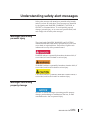
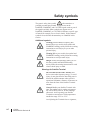
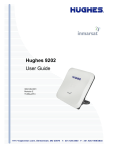
Hughes 9450 Series
User Guide
3004128-0001
Revision B
February 29, 2012
Copyright © 2012 Hughes Network Systems, LLC
All rights reserved. This publication and its contents are proprietary to Hughes Network
Systems, LLC. No part of this publication may be reproduced in any form or by any
means without the written permission of Hughes Network Systems, LLC, 11717
Exploration Lane, Germantown, Maryland 20876.
Hughes Network Systems, LLC has made every effort to ensure the correctness and
completeness of the material in this document. Hughes Network Systems, LLC shall not
be liable for errors contained herein. The information in this document is subject to
change without notice. Hughes Network Systems, LLC makes no warranty of any kind
with regard to this material, including, but not limited to, the implied warranties of
merchantability and fitness for a particular purpose.
Trademarks
Hughes and Hughes Network Systems are trademarks of Hughes Network Systems,
LLC. All other trademarks are the property of their respective owners.
Contents
Understanding safety alert messages ........................................................................................v
Messages concerning personal injury ........................................................................................................ v
Messages concerning property damage ..................................................................................................... v
Safety symbols ........................................................................................................................... vi
Introduction .................................................................................................................................1
Overview .................................................................................................................................................... 1
About this User Guide ............................................................................................................................... 2
Package Contents ....................................................................................................................................... 2
Minimum System Requirements for Laptop/PC ........................................................................................ 3
Getting Started ........................................................................................................................................... 3
Installing your terminal .............................................................................................................................. 3
Terminal LED functionality ....................................................................................................................... 3
Using the Hughes 9450................................................................................................................5
Auto start configuration ............................................................................................................................. 5
Power up and the connection to the Internet .............................................................................................. 6
Connecting the terminal to the computer ................................................................................................... 7
Connecting by Ethernet .......................................................................................................................... 7
Power over Ethernet (POE).................................................................................................................... 7
Connecting by WLAN ........................................................................................................................... 8
WEP Security ..................................................................................................................................... 8
Connecting by ISDN .............................................................................................................................. 9
Connecting by RJ-11 .............................................................................................................................. 9
Coverage Map .......................................................................................................................................... 10
Using the Web UI ......................................................................................................................11
Accessing the Web UI ............................................................................................................................. 11
Home page ............................................................................................................................................... 12
Connections.............................................................................................................................................. 15
Manage Connections ............................................................................................................................ 15
Automatic Contexts.............................................................................................................................. 16
Manage APNs ...................................................................................................................................... 21
SMS ......................................................................................................................................................... 23
Send/Receive........................................................................................................................................ 23
Saved Drafts ......................................................................................................................................... 24
Sent Messages ...................................................................................................................................... 25
SMS Settings ........................................................................................................................................ 26
Settings page ............................................................................................................................................ 27
x Contents
3004128-0001 Revision B
iii
General Setup ....................................................................................................................................... 27
IP Address/DHCP Settings .................................................................................................................. 28
Nat Mode.......................................................................................................................................... 29
Relay Mode ...................................................................................................................................... 29
Wireless LAN ...................................................................................................................................... 30
Wireless LAN Security ........................................................................................................................ 31
Telephony ............................................................................................................................................ 33
Security ................................................................................................................................................ 35
Features ................................................................................................................................................ 36
Usage Page ............................................................................................................................................... 37
Support Page ............................................................................................................................................ 38
Troubleshooting ........................................................................................................................41
Technology Overview ...............................................................................................................44
GPS .......................................................................................................................................................... 44
Obtaining a GPS Fix ............................................................................................................................ 44
GPS and BGAN Registration ............................................................................................................... 45
ISDN ........................................................................................................................................................ 45
Dialing and Numbering........................................................................................................................ 45
PDP Context............................................................................................................................................. 45
Technical Specifications ...........................................................................................................47
Declaration of Conformity .......................................................................................................48
FCC Compliance...................................................................................................................................... 49
EU RoHS (Restriction of Hazardous Substances) Directive ................................................................... 49
EU WEEE (Waste Electrical and Electronic Equipment) Directives ...................................................... 50
Glossary .....................................................................................................................................51
iv
x Contents
3004128-0001 Revision B
Understanding safety alert messages
Safety alert messages call attention to potential safety hazards
and tell you how to avoid them. These messages are identified
by the signal words DANGER, WARNING, CAUTION, or
NOTICE, as illustrated below. To avoid possible property
damage, personal injury, or in some cases possible death, read
and comply with all safety alert messages.
Messages concerning
personal injury
The signal words DANGER, WARNING, and CAUTION
indicate hazards that could result in personal injury or in some
cases death, as explained below. Each of these signal words
indicates the severity of the potential hazard.
DANGER indicates a potentially hazardous situation which, if
not avoided, will result in death or serious injury
WARNING indicates a potentially hazardous situation which, if
not avoided, could result in death or serious injury.
CAUTION indicates a potentially hazardous situation which, if
not avoided, could result in minor or moderate injury.
Messages concerning
property damage
NOTICE is used for messages concerning possible property
damage, product damage or malfunction, data loss, or other
unwanted results—but not personal injury.
x Safety
3004128-0001 Revision B
v
Safety symbols
The generic safety alert symbol
calls attention to a
potential personal injury hazard. It appears next to the
DANGER, WARNING, and CAUTION signal words as part of
the signal word label. Other symbols may appear next to
DANGER, WARNING, or CAUTION to indicate a specific type
of hazard (for example, fire or electric shock). If other hazard
symbols are used in this document they are identified in this
section.
Additional symbols
Warning Potential Radio Frequency (RF)
hazard. Where you see this alert symbol and
WARNING heading, strictly follow the warning
instructions to avoid injury to eyes or other
personal injury.
Warning Where you see this alert symbol and
WARNING heading, strictly follow the warning
instructions to avoid personal injury.
Danger Electric shock hazard: Where you see
this alert symbol and DANGER heading,
strictly follow the warning instructions to avoid
electric shock injury or death.
Warnings for Satellite Terminal
Do not stand in front of the Antenna This
device emits radio frequency energy. To avoid
injury, do not place head or other body parts in
front of the satellite antenna when system is
operational. Maintain a distance of one meter or
more from the front of the Satellite Terminal
antenna.
General Handle your Satellite Terminal with
care. The outdoor unit is weather resistant per
IEC 60529 IP56; however, do not submerge
either unit. Avoid exposing your Satellite
Terminal to extreme hot or cold temperatures
outside the range -25ºC to +55ºC.
Avoid placing the Terminal close to cigarettes,
vi
x Safety
3004128-0001 Revision B
open flames or any source of heat.
Changes or modifications to the Terminal not
expressly approved by Hughes Network
Systems could void your authority to operate
this equipment.
Only use a soft damp cloth to clean the
Terminal.
To avoid impaired Terminal performance, please
ensure the unit’s antenna is not damaged or
covered with foreign material like paint or
labeling.
When inserting the SIM, do not bend it or
damage the contacts in any way. When
connecting the interface cables, do not use
excessive force.
In the vicinity of blasting work and in
explosive environments Never use the Satellite
Terminal where blasting work is in progress.
Observe all restrictions and follow any
regulations or rules. Areas with a potentially
explosive environment are often, but not always,
clearly marked. Do not use the Terminal while
at a petrol filling station. Do not use near fuel or
chemicals.
Qualified Service Do not attempt to
disassemble your Satellite Terminal. The unit
does not contain consumer-serviceable
components. Only qualified service personnel
may install or repair equipment.
Accessories Use Hughes approved accessories
only. Use of non-approved accessories may
result in loss of performance, damage to the
Satellite Terminal, fire, electric shock or injury.
Connecting Devices Never connect
incompatible devices to the Satellite Terminal.
When connecting the Satellite Terminal to any
other device, read the device’s User Manual for
detailed safety instructions.
x Safety
3004128-0001 Revision B
vii
Pacemakers The various brands and models of
cardiac pacemakers available exhibit a wide range
of immunity levels to radio signals. Therefore,
people who wear a cardiac pacemaker and who
want to use a Satellite Terminal should seek the
advice of their cardiologist. If, as a pacemaker
user, you are still concerned about interaction with
the Satellite Terminal, we suggest you follow these
guidelines:
x
Maintain a distance of 20cm from the WiFi antenna and your pacemaker:
x
Maintain a distance of one meter from the
main antenna front and sides and your
pacemaker;
x
Refer to your pacemaker product literature
for information on your particular device.
If you have any reason to suspect that interference
is taking place, turn off your Satellite Terminal
immediately.
Hearing Aids Most new models of hearing aids
are immune to radio frequency interference from
Satellite Terminals that are more than 2 meters
away. Many types of older hearing aids may be
susceptible to interference, making it very difficult
to use them near a Terminal. Should interference
be experienced, maintain additional separation
between you and the Satellite Terminal.
Electrical Storms Operation of the Satellite
Terminal during electrical storms may result in
severe personal injury or death. Ensure the Below
Deck Equipment is properly grounded to the
vehicle chassis.
viii
x Safety
3004128-0001 Revision B
Introduction
Overview
The Hughes Network Systems 9450 Broadband Satellite
Terminal is your gateway to global communication. The 9450
terminal allows you to simultaneously send and receive IP
packet and circuit-switched data via Ethernet (Power over
Ethernet) ports and the Integrated Services Digital Network
(ISDN) interfaces over the Inmarsat BGAN satellite network.
This unit offers you the following features and benefits:
x Fully autonomous tracking antenna acquires and tracks the
BGAN satellite signal while on the move
x Optional antenna installation (magnetic mount) on vehicle
roof
x Includes RF cable and power cable for vehicular installation
x Up to 464 Kbps data (transmit and receive) and 128 Kbps
streaming IP data rate
x 4 X RJ-45 Power over Ethernet (PoE) ports
x ISDN 3.1KHz audio (above 45 degrees look angle to the
satellite)
x ISDN UDI/RDI data (64Kbps) (above 45 degrees look angle
to the satellite)
x Multi-user capability for sharing a single unit
x Selectable Quality-of-Service (QoS)
x Full IP compatibility for Email, file transfer (FTP),
browsing, VPN, etc.
x Cost-effective “always-on” access – charges only for data
sent and received
x UMTS IP-based services
x FCC and CE certified
x Subscriber Identification Module (SIM) card security
With the optional antenna installation method, the unit is easy to
install and connects in minutes. It is built for use in vehicular
environments.
In this document, the following names and abbreviations are
used to identify the Satellite Terminal and your computer.
x Introduction
3004128-0001 Revision B
1
Term
Definition
IDU
Indoor Unit
ODU
Outdoor Unit/antenna
Terminal Satellite Terminal
TE
Terminal Equipment (your computer)
UT
User Terminal/satellite terminal
About this User Guide
This user guide contains the most up-to-date information
available on this product, on the date it was generated. It is
focused on the specific information needed to operate the
Hughes 9450 Land Mobile User Terminal.
For information on using LaunchPad, please refer to the
Inmarsat website where a copy of the ‘Inmarsat LaunchPad
Guide’ can be downloaded:
http://www.inmarsat.com/Support/BGAN/LaunchPad.aspx?l
anguage=EN&textonly=False
Package Contents
When you unpack the Land Mobile Terminal Kit package, you
will find the following:
x BGAN Land Mobile Tracking Antenna Kit
x Hughes 9450 BGAN Satellite Modem Kit
Your Service Provider will supply you with a Subscriber
Identification Module (SIM) and its PIN, and Satellite Terminal
configuration instructions – you will need these to access the
network. Note: The SIM card may also have four (4) MSISDN
numbers associated with it for various ISDN services:
x
x
x
x
2
x Introduction
3004128-0001 Revision B
4K Voice
3.1KHz Audio/Fax
64K UDI data
56K RDI data
Minimum System
Requirements for
Laptop/PC
These are the minimum computer system requirements for
successful interface with the Satellite Terminal:
x Internet Browser: Microsoft Internet Explorer (IE7 or IE8),
Mozilla or Safari.
x PC Support for at least one of these interfaces: Ethernet, or
WLAN (802.11b or b/g).
x 100 MB of free hard disk space if using LaunchPad.
Getting Started
This guide is the simplest and quickest way to connect to the
BGAN network. If you are a first time user, you will be guided
through the procedure for powering up your terminal,
obtaining a GPS fix, connecting your computer to the terminal
and registering with the BGAN network. You are then ready to
start using voice and broadband services.
Installing your terminal
Install the Hughes 9450 terminal according to the Installation
Guide P/N 3004129 supplied with the terminal. Please refer to
the Installation Guide for grounding instructions.
Terminal LED
functionality
The 9450 IDU has 4 LEDs with the following functions:
Power: Green when IDU is powered on. Off when IDU is
powered off. This LED is integrated in the On/Off switch.
Network Registration: Green when registered and attached with
Inmarsat BGAN network, Off otherwise.
GPS: Flashing Green while acquiring fix and solid Green when
valid GPS fix acquired, off otherwise.
H/W Fault: Red if HW fault detected, e.g.: IB fault, no
communication to antenna or no GPS. Off otherwise.
x Introduction
3004128-0001 Revision B
3
The 9450 IDU has a four RJ-45 connector with 2 LEDs for each
port with the following functions:
Green/Red bicolor: Green indicates Link active; Red indicates a
power over Ethernet PD device is connected and is being
powered by the IDU. When both functions are active, it will
appear Orange in color.
Green: Traffic indicator
4
x Introduction
3004128-0001 Revision B
Using the Hughes 9450
Auto start configuration
Since the Hughes 9450 terminal is equipped with a tracking
antenna, the default configuration for the Hughes 9450 Land
Mobile Terminal is as follows:
x The Hughes 9450 is configured to automatically register
with the network by default: The terminal will automatically
attempt to register with the network once the tracking
antenna has acquired the satellite signal and obtained a GPS
fix.
x The IDU has a power switch and an ignition sense line. For
the unit to turn on, the power switch must be in the ON
position and 12V or 24V applied to the ignition sense line.
Refer to the 9450 Installation Guide P/N 3004129-0001.
x Using the Hughes 9450
3004128-0001 Revision B
5
These default configurations are accessible through LaunchPad
or the web UI and it is recommended to keep these settings for
convenient operation of the Hughes 9450 Land Mobile Terminal.
Power up and the
connection to the
Internet
After power is applied, the Hughes 9450 IDU and Hughes
Tracking Antenna will begin their start-up sequence. The
tracking antenna will begin its search for the BGAN satellite
and the antenna motors may be heard during this time. Note
that the tracking antenna must have line of sight to the BGAN
satellite. Once the antenna has locked onto the BGAN satellite,
it will continue to make minor adjustments to acquire optimum
signal strength. The antenna may be heard ‘twitching’ during
this time. Eventually the antenna will sit at an optimum
position while the vehicle is stationary.
Once the vehicle starts moving, the Hughes Tracking Antenna
will automatically track the satellite signal and keep the
antenna pointed towards the satellite. During short outages
(e.g. while driving under a bridge, etc.) the antenna will remain
in the same position and will pick up the satellite signal
immediately. For longer outages the antenna may need to
repeat the search pattern to reacquire the satellite signal.
Circuit switched and packet switched connections will
typically recover from signal outages of less than 60
seconds. User intervention will be required to reactivate
circuit switched connections for outages longer than 60
seconds and may be required for packet switched
connections depending upon the actual length of outage.
Packet switched connections like FTP are more robust than
circuit switched connections in the network.
6
x Using the Hughes 9450
3004128-0001 Revision B
Connecting the terminal
to the computer
You can connect your computer to the 9450 IDU with one or
more of the following interfaces
x Ethernet
x WLAN
x Integrated Services Digital Network (ISDN)
There is no need to check the active interface. All
interfaces can be used simultaneously to accommodate
multiple users.
x
During initial setup, the terminal can only be configured
using an Ethernet connection. Once the terminal has been
configured, all interfaces (Ethernet, WLAN and ISDN) can
be used for data transfer depending on the service required.
Your computer must be configured to support your chosen
connection method. Refer to the documentation supplied
with your computer for details.
Connecting by Ethernet
To connect the BGAN terminal to a device using Ethernet:
x Connect an Ethernet cable to your device’s Ethernet port,
and insert the other end of the connector into one of the four
Ethernet ports on the 9450 IDU. These four Ethernet ports
support Power-over-Ethernet (PoE).
Power over Ethernet (POE)
x All 4 ports are powered by a single 48Volt DC power supply
capable of outputting 61.2 Watts and 30.6 Watts at 24 Volts
and 12 Volts input respectively. The ports can provide power
to class 1, 2, and 3 devices as long as the total power does
not exceed the wattage based on the input voltage provided.
If a device is connected to a port that exceeds the maximum
power available, power will not be provided to that port. The
existing connections will not be affected.
x Using the Hughes 9450
3004128-0001 Revision B
7
Connecting by WLAN
If you have not previously used the IDU’s WLAN interface, it
has to be enabled from the internal web UI or LaunchPad with
your computer connected to the IDU using the Ethernet
interface.
x WLAN Power: The default is off, which disables the
WLAN feature.
x SSID (network name): The default is BGAN, but you can
change it to whatever you want.
x Channel Number: This controls the radio channel number (1
through 11) used by the access point. To meet FCC
regulations, channels 12 to 14 are not supported.
As you are configuring the WLAN, you can enable the
Wireless Encryption Protocol (WEP), MAC address filtering
and no broadcast SSID features for added security.
Once the WLAN is “Enabled” and configured, any device with
a WLAN interface can detect the IDU’s WLAN SSID, and
connect to it automatically.
WEP Security
x WEP Protection Status: Check the box to “Enable” the WEP
for added security. Encryption Level: 64 or 128 bit WEP
encryption can be enabled.
x WEP Key: You can define the WEP key or use the default
WEP key, which is formulated using the IMEI number of the
terminal (e.g. IMEI number +0123456789).
x Hexadecimal 128-bit: Requires 26 characters.
Recommended
x Hexadecimal 64-bit: Requires 10 characters
x SSID Broadcast: For added security you can choose not to
broadcast your SSID.
x MAC Filtering: For added security, check the box to
“Enable” MAC Filtering. You can define up to 10 MAC
addresses that are allowed to connect to your WLAN.
To determine the MAC address of a PC, go to a DOS prompt
and type ipconfig/all.
8
x Using the Hughes 9450
3004128-0001 Revision B
For Mac OS X, under the Apple Menu go to System
Preferences -> Network and Show Airport. The Airport Id is
the MAC address. Alternatively, go to About this Mac ->
More Info -> network, and select Airport.
When WLAN is enabled, unauthorized users may be able to
access your BGAN service. If WEP is enabled, you must
provide other WLAN users with the WEP key in order for
them to connect to the terminal. You can go to the Manage
Connections page to see what computers are actually using the
BGAN service.
Connecting by ISDN
Connect an ISDN cable to your computer’s or phone’s ISDN
port, and insert the other end of the connector into the
Terminal’s ISDN port.
To dial, prefix the international number with 00 and terminate
with #. For example, to dial a number in the USA, enter:
0018005551234#
To receive incoming calls you must configure your ISDN
device with the MSN (Multiple Subscriber Number) of the
service it supports. See the ISDN section for information on
configuration of MSNs. To configure the MSN in your ISDN
device, refer to the user guide of your ISDN device.
Connecting by RJ-11
You can connect an analog phone or fax machine to the RJ-11
ports:
x The FAX port is configured for 3.1k service for fax
x The TEL port is configured for speech service for voice calls
To dial, prefix the international number with 00 and terminate
with #. For example, to dial a number in the USA, enter:
0018005551234# (00 + Country code + phone number)
Operational note: RJ-11 and ISDN handsets cannot be
connected at the same time. The 9450 will configure itself to
ISDN or RJ-11 mode depending on which type of handset is
plugged in first, and will be in this mode thereafter.
x Using the Hughes 9450
3004128-0001 Revision B
9
To switch modes, the 9450 must be rebooted with only the
desired handset connected. If both types of handsets are
connected at power-on, the 9450 will default to ISDN mode
and RJ-11 will not be operational.
Coverage Map
The Inmarsat BGAN service is operated with 3 satellites as
shown below. The Hughes 9450 terminals will perform best in
areas where the elevation angle is 20 degrees or higher. Lower
elevation angles increase the probability of signal outages
caused by trees, buildings and hilly terrain and may severely
impact the usability on the move.
10
x Using the Hughes 9450
3004128-0001 Revision B
Using the Web UI
Accessing the Web UI
The Hughes UT includes its own internal Web User Interface
(UI). To access the web UI, open your favorite Web Browser
and type in the internal IP address of the UT e.g.
http://192.168.128.100. The web UI opens up to the “Home”
page as shown below:
x Using the Web UI
3004128-0001 Revision B
11
Home page
The Home page shows the current terminal status and allows
you to setup your initial data connection.
On the left side of the page is the Status bar. These items are
updated automatically when the status of any of these items
change.
1. Connection: This field indicates whether you are
Registered with the Network. It also shows the PS and CS
status, beam type and receive signal quality.
a. PS Attach Status: This field indicates whether you
are PS (Packet Switch) attached with the Network.
You will still need to setup a PDP context in order to
send PS data.
b. CS Attach Status: This indicates whether you are CS
(Circuit Switch) attached with the Network. Once you
are CS Attached and Registered with the network, you
are able to make CS calls.
2. GPS: This field displays the current GPS position status.
If you have received a GPS fix and the Network GPS
policy has been received and it allows the GPS position to
be shown to the user, it will display the Latitude,
Longitude, Fix Quality, and the Last time the GPS position
was updated. Time displayed is UTC time.
3. BGAN terminal: This field indicates the WLAN status.
4. Antenna Unit: This field indicates the detailed state of the
tracking antenna
a. The state field indicates the tracking state of the
antenna
b. Elevation: the current elevation look angle of the
antenna
c. The frequency of the global beam in MHz that the
antenna is attempting to track is displayed. If the unit
is experiencing problems, use the table below to verify
the antenna is searching for the correct satellite for
your location
The frequency is the frequency of the global beam.
Possible values are the primary and secondary frequencies
of the three satellites.
12
x Using the Web UI
3004128-0001 Revision B
Satellite ID
Satellite
Longitude
Primary Freq
MHZ
Alternate MHz
I4-F1 Asia
Pacific
143.5 E
1537.485
1540.825
I4-F2 Europe,
Middle East &
Africa
25.0 E
1537.920
1541.115
I4- Americas
98.0 W
1537.070
1540.730
In the middle of the page you will find the following items:
Current Connection field allows you to activate data
connections for your TE. You can activate a Standard connection
or a Streaming connection. For streaming connections use the
drop down box to select the data rate for the stream.
Connect using APN field allows you to control the APN used
for the connection.
Details show the status of the connection for this TE.
Visible Satellites shows the satellites visible for your current
location and the pointing information.
Reference the screenshot below. The antenna angle under
Visible Satellites section (46.3°) may not be exactly the same as
seen under the Antenna Unit section showing Elevation (40°).
This is due to the wide beam width of the antenna
The following figure shows how the UI looks if you activate a
Standard connection. Use the Disconnect button to deactivate
your connection.
x Using the Web UI
3004128-0001 Revision B
13
14
x Using the Web UI
3004128-0001 Revision B
Connections
The Connections icon has three configuration areas to select
from: Manage Contexts, Automatic Context Activation (ACA),
and Manage APN. The following section will review each of
these pages.
Manage Connections
Manage Connections page under the Data tab allows the user to
setup and configure PDP contexts (data connection) for any TE
that is connected to the UT. It also shows you all current Active
Connections.
Open a New Connection - To open a new connection, enter the
required data in the lower box.
Owner – Your current IP address is shown by default (.101), but
you can change it to control connections for any other device
x Using the Web UI
3004128-0001 Revision B
15
connected to the terminal. The page automatically displays
entries for all detected devices and these entries can be selected
to activate connections for those devices.
Service - Select the service that you want by clicking on the
down arrow. The drop down list shows all of the different QoS
types: standard, streaming 32K, streaming 64K, and streaming
128K. Select the appropriate service required.
APN - The APN is read from the SIM card, but if you have other
APN’s defined (go to Manage APN page), you can use the down
arrow to select a different APN. Once everything is defined
correctly, click on the “Open Selected Connection” button. The
new context will appear in the All Active Connections field
above.
Close a Connection - In the upper field, all active connections
are shown and you can select and close any of these connections
unless an Administration Password has been enabled. See
Security Section for more information about the administration
password.
Username (UN)/Password (PW): Some Service Providers
require a username and password to be used when setting up a
connection. This is often required when using Static Global IP
addresses assigned by the Service provider. These fields can be
entered when defining a new APN or when you select a different
APN.
Automatic Contexts
This web page allows you to use Automatic Context Activation
(ACA) in two different ways;
x One way is to use a static IP addresses in the TE device so
you can establish an automatic PDP context with any QoS
that is offered by the network (upper half of the web page).
x The second way is to use DHCP IP addresses from the UT
so you can establish an automatic standard PDP context for
16
x Using the Web UI
3004128-0001 Revision B
any TE that connects via DHCP to the UT (lower part of the
web page).
x You can also choose whether the context should be activated
as soon as the UT detects the device, or if the context should
only be activated when the TE attempts to send data to the
satellite link. For the “data activated” option, choose “Data”
from the drop down list rather than just On in either static or
DHCP sections.
With “Data activation”, if the context is ever deactivated, it
will be reactivated when more data is sent.
Static IP Automatic Contexts:You can configure your own
range of static IP addresses and QoS’s to use with a static
automatic context.
To turn on a particular range of static addresses, select “On” or
“Data” from the drop down list and choose a range of addresses,
low and high to use (e.g. 192.168.128.200 to 192.168.128.202)
or you can leave the defaults (192.168.128.200 to
192.168.128.209).
Next select the desired QoS for that range of IP addresses (e.g.
Standard). The APN listed is the default APN read from the
SIM card (bgan.inmarsat.com). If your SIM is provisioned for
more than one APN, then you can select a secondary APN from
the drop down list.
x Using the Web UI
3004128-0001 Revision B
17
If you want to setup additional ranges of addresses, please follow
the same instructions as above.
You cannot overlap the IP address ranges. If you do, an error
will pop-up telling you that you have an overlap region. Check
all of the ranges for overlaps and try again.
When you are finished, click on “Apply” and you should see a
message saying “Operation Successful”.
DHCP Automatic Contexts: This option allows you to set up
the UT for dynamic standard ACA. This means that any device
connected to the UT via DHCP, whether wired or wirelessly will
automatically receive a standard context.
To activate this feature, select “On” or “Data” from the drop
down list under DHCP Automatic Context section, select the
DHCP range of addresses to use if you don’t want to use the
18
x Using the Web UI
3004128-0001 Revision B
default (.101 -.199) and click on “Apply”. The APN will be the
default APN configured on the Manage APNs page.
Once you hit “Apply” you will get a pop-up message saying that
the ACA settings were updated successfully and to take effect
you will have to reboot the terminal.
x Using the Web UI
3004128-0001 Revision B
19
Once you reboot the terminal, check that the settings took effect.
To see if the context has been setup properly, click on the “Data
tab>Manage Connections Page and this will show you all
contexts that have been setup (active or inactive). See screen
shot below.
20
x Using the Web UI
3004128-0001 Revision B
Manage APNs
Some SIM cards are provisioned with multiple APNs, so you can
use this page to pre-configure those additional APNs if needed.
Once the APN is defined, you can select it from the drop down
list without having to put in the username and password every
time.
Add an APN field – Use this field to add an additional APN that
you want to use, or to edit an existing APN. For adding a new
APN, type in the new APN, username and password (if required)
then select Add New APN. If you want to save the username
and password so you don’t have to re-type it each time you
configure a PDP context for that APN, check the Save User
Name / Password box and then click the Add New APN button.
The new APN name will show up in the Defined APNs field.
This APN will now be available to use from any APN drop
down menu.
User Name /Password: Some Service Providers require a
username and password to be used when setting up a connection.
x Using the Web UI
3004128-0001 Revision B
21
This is often required when using Static Global IP addresses
assigned by the Service provider.
The screenshot above shows the new APN that was added, in the
Defined APNs section.
If you wish to edit an existing APN, first select the APN to edit
under the Defined APNs section on the left. The information for
that APN will then appear in the Add an APN field to the right,
and you can then edit it. Click the Save Changes button to save
your changes.
Make Default. If you wish to change the default APN, select an
entry in the list of Defined APNs and then click Make Default.
This APN will now be the default APN on the other context
control pages. Note that already configured static ACA entries
must be manually updated to change the APN.
22
x Using the Web UI
3004128-0001 Revision B
SMS
You can manage SMS text messages from the SMS pages which
provide a similar function to LaunchPad. You must have a valid
Service Center number configured in order to send messages –
see the SMS Settings Page.
Send/Receive
The Send/Receive page allows you to view your Inbox box
messages and Compose a new message. If there are more than
10 messages, you can view the older ones by changing the page
number. You can also reply to received messages or forward
them to another number.
You may need to periodically delete messages to prevent the
SIM from filling up which will prevent the receipt of new
messages. You can select a single message by checking the box
next to the message and press the “Delete Checked” button. To
delete multiple messages just select the check box next to each
message you want to delete and click the “Delete Checked”
button.
After composing a message you can save it to drafts rather than
sending it, by pressing the “Save” button.
x Using the Web UI
3004128-0001 Revision B
23
Saved Drafts
The Saved Drafts page allows you to view previously saved
messages. After editing a message you can resave (Save) or send
the message (Send). You can also compose a message from this
page.
24
x Using the Web UI
3004128-0001 Revision B
Sent Messages
The Sent Messages page allows you to view previously sent
messages. Again, you may need to periodically delete messages
to prevent the SIM from filling up. You can also compose a new
message from this page.
x Using the Web UI
3004128-0001 Revision B
25
SMS Settings
On the SMS Settings page you can configure the default settings
for messages. You must have a valid Service Center number
configured in order to send messages. The default Service
Center number is +870772001799.
On the Remote SMS Feature section you can enable the unit to
receive and act on special remote control SMS messages.
Contact your service provider for more information on this
feature. Before this feature can be enabled you must obtain the
feature activation code from your service provider and activate
the feature from the Features Web page.
You can configure the password that must be contained in
remote control SMS messages. Be sure to make a note of the
password if you change it from the default. Note: If you activate
this feature and do not change the password, it is possible that
other people may be able to send control messages to your unit.
Remote control messages will be deleted after they are received
and will not be stored in the SIM.
26
x Using the Web UI
3004128-0001 Revision B
Settings page
General Setup
This page allows the user to configure various parameters of the
UT. A description of each item on this page follows:
Terminal Startup – The default configuration for the 9450
terminal has Bypass Antenna pointing and Always power on
checked and grayed out due to the tracking antenna.
Connection – The default configuration is always set to
Automatic. This parameter is used within a satellite overlap
region and allows the user to override the default satellite
(selected by the 9450 terminal based upon elevation angle/GPS
location) and select a different satellite.
This change does not take effect until the UT is reset. When set
to Automatic, the UT will select the satellite based on the unit’s
GPS position. When set to a specific satellite, it will attempt to
use that satellite only. Be careful to select the correct satellite for
your position.
x Using the Web UI
3004128-0001 Revision B
27
Streaming – By enabling this parameter, the user can turn on a
timer for inactivity for a streaming QoS that has been set up.
The timer is in either seconds or minutes and will tear down a
streaming context after X seconds or minutes of inactivity.
Emergency Call Numbers: Allows the user to add the
emergency call number that is applicable in the part of the world
where the terminal is being used, if it is not already defined.
IP Address/DHCP Settings
Terminal Local IP Address: This page allows the user to change
the local IP address of the terminal from the default
192.168.128.100 IP address. All four octets are available to
change. Once the local IP address is changed on this page and
applied, the IP address ranges for the DHCP server, the Manage
Context page and ACA page will also be changed automatically.
Updates to this field will not take effect until the UT is
rebooted.
28
x Using the Web UI
3004128-0001 Revision B
DHCP Server: allows the DHCP server in the UT to be turned
on or off by checking the Enable box.
DHCP Address Range: This allows the user to set the range of
DHCP addresses that are given out by the UT to any connected
TE.
Lease Time when idle: Idle-mode DHCP Lease Time refers to
the DHCP lease time when the UT is not connected to the
network. This parameter allows the user to change the default
time (60 seconds) that the DHCP lease to the TE is good for.
This parameter was introduced because of a problem with some
models of Cisco routers that will not accept a short DHCP lease
time.
The longer the Idle-mode DHCP lease time, the longer it will
take the Network/UT to update the TE with the correct DNS
servers for web browsing after establishing a data context.
Lease Time when connected: The Connected-mode DHCP
Lease Time refers to the DHCP lease time when the UT is
connected to the network. Most users will have no need to
change this parameter.
Network Operating Mode: The Netmode field indicates the
mode of operation of the terminal. In NAT mode the UT will
translate between the local and global IP addresses. In Relay
mode the UT will supply the global IP address to the TE once a
PDP Context is established. Relay mode is single user/single
PDP Context and only supports a single connected TE. Note:
Updates to this field will not take effect until the UT is restarted.
Nat Mode
In NAT mode once a PDP context is active, the UT will
translate between the local and global IP addresses. This is a
basic NAT that only performs IP address translation. It does not
use port translation.
Relay Mode
In Relay mode the UT will supply the global IP address to the
TE when the context is established. Relay mode is single user
and only supports a single connected TE.
In Relay mode DHCP is required to provide the global IP
address to the TE. When the context is activated, the DHCP
x Using the Web UI
3004128-0001 Revision B
29
server in the UT will NACK the next DHCP lease renewal from
the TE and assign the global IP address assigned by the network.
The local IP connection will be torn down and reestablished as
the IP address changes. Similarly, when the context is
deactivated the DHCP server will NACK the lease renewal and
then reassign the original private IP address.
LaunchPad and the Web UI will lose and reestablish their
connections to the terminal as the IP address is changed.
To make the IP address change happen quickly a short DHCP
lease should be used. The terminal defaults the DHCP lease time
to 60 seconds in idle and connected mode.
Relay mode only supports a single user TE.
Wireless LAN
The Wireless LAN settings page allows the user to enable,
disable, and configure the Wireless LAN functionality of the
terminal.
30
x Using the Web UI
3004128-0001 Revision B
The Wireless LAN Security is controlled on a separate web page
– WLAN Security.
If you have not previously used the terminal’s WLAN interface,
it has to first be enabled from this page using a computer
connected to the terminal using an Ethernet connection. Once
WLAN is enabled/configured, TEs can connect to the terminal
wirelessly.
Fields on this page include:
Enable Wireless LAN Interface: Turns the Wireless LAN
interface on/off. The default is off (unchecked).
Network Name (SSID): The default is “BGAN”, but you can
change it to whatever you want.
You can “hide”/prevent the SSID broadcast on the WLAN
Security page
Network Region: There is only one region for all countries.
Network Channel: This controls the radio channel number (1
through 11) used by the access point. To meet FCC regulations,
channels 12 to 14 are not supported.
If performance issues occur over the WLAN interface, changing
the Channel may help.
Wireless LAN Security
This page allows the user to configure WEP Security for use
when the terminal is communicating wirelessly to TEs.
Additional security measures that can be used with WEP to
make it more secure are: 1) Do not broadcast your SSID and 2)
enable MAC address filtering so that only the MAC addresses
that you select, can connect to the terminal. A maximum of ten
(10) addresses can be filtered.
Check the box if you want your SSID name to be broadcast.
Select from the down arrow, No protection, 64 bit WEP and 128
bit WEP.
x Using the Web UI
3004128-0001 Revision B
31
Mac Address Filtering
Check the box to “Enable MAC Address Filtering”
If any TE is already connected to the terminal wirelessly, the
MAC address of that TE will be detected and show up in the
“Add a Detected Device” field.
To add the detected MAC address, click on the address
to highlight it and then click Add. It will now show up
in the “Allowed MAC Address” field.
32
x Using the Web UI
3004128-0001 Revision B
Telephony
You can establish ISDN data communication by connecting your
ISDN equipment directly to the BGAN Terminal’s ISDN port
with an ISDN cable (which is the same as the Ethernet cable).
The Telephony page allows you to activate 40V power sourcing
on the ISDN interface, and configure Device MSN Settings.
General ISDN Settings:
Enable ISDN Power Sourcing: To turn on the ISDN power
sourcing, click the check box in the upper left-hand corner that
says “Enable ISDN Power Sourcing” and then click on
“Apply”. The ISDN device should receive 40V power
immediately via the ISDN cable. This field should be on
unless you never use ISDN or are using an ISDN device that
has its own power source.
Select the outgoing call type using: This box controls the
mechanism used by the terminal to select the bearer type for
mobile originated calls. By default, “the Device Bearer
capability” is set as the trigger in this drop down list. Most
ISDN devices correctly signal the call type (speech, 3.1KHz
audio, UDI, RDI) via the bearer capability.
There is also an option under the drop down arrow to set the
trigger to use the MSN rather than the bearer. If there is a
problem using the bearer capability setting, this field can be
changed to use the MSN number instead.
x Using the Web UI
3004128-0001 Revision B
33
Device MSN Settings - Voice/FAX Devices
Standard Voice: By default, MSN 1 is used for standard voice
(speech). To receive incoming calls, you must program the
same MSN into your ISDN handset connected to the ISDN
port.
Premium Voice/Fax (3.1 kHz Audio): By default, MSN 2 is
used for 3.1 KHz Audio. To receive incoming calls, you must
program the same MSN into your ISDN fax machine
connected to the ISDN port.
Device MSN Setting - 64 kbps Data Devices
64 kbps Clear Data UDI (Unrestricted Digital
Information): By default, MSN 3 is used for UDI calls. UDI
is a 64 Kbps service that is a European standard ISDN.
64 kbps Restricted Data RDI (Restricted Digital
Information): By default, MSN 3 is used for RDI calls. RDI
is a 56 Kbps service found in the USA.
Once all changes have been made, click on “Apply”.
You can use different MSNs for any of the ISDN call types
above, but your ISDN equipment must be programmed with the
same MSN to accept incoming calls, and you must use different
numbers for speech, audio and UDI/RDI calls.
General Telephony Settings:
Call Progress Tones: Two options are provided for call
progress tones. Option 1 is the default tones used in the USA.
Option 2 provides an alternative set of tones that are used in
Brazil and some European countries.
Option 1 (US)
Call Progress
Tone
Freq (Hz)
Cadence
Dial
350 + 440 Steady ON
Ring Back
440 + 480 2 sec ON
4 sec OFF
Repeating
Network
480 + 620 0.25 sec ON
Congestion
0.25 sec OFF
Repeating
Busy
480 + 620 0.5 sec ON
0.5 sec OFF
Repeating
34
x Using the Web UI
3004128-0001 Revision B
Option 2 (Alternative)
Freq (Hz)
Cadence
425
Steady On
425
1 sec ON
4 sec OFF
Repeating
425
0.5 sec ON
0.5 sec OFF
Repeating
425
0.25 sec On
0.25 sec OFF
Repeating
Security
You can configure three separate security settings on this page:
1) SIM PIN, 2) Phone to SIM PIN, and 3) Administration
Password.
SIM PIN – this is a four digit field can be Enabled and
configured by the user to secure the terminal against unwanted
use. Once enabled, the terminal will require the SIM PIN at
startup.
Phone to SIM PIN – use up to 5 digits to lock the terminal to
that particular SIM. The Phone to SIM PIN will have to be
entered any time the SIM card is changed. This setting is similar
to a GSM phone’s security code. Default password is 12345.
Administration Password – this configuration allows the user
to prevent terminal settings from being changed once the
terminal is configured properly. This password will have to be
entered before any settings can be changed.
x Using the Web UI
3004128-0001 Revision B
35
Features
You can enable special features from this page.
SMS Remote Management allows the unit to receive and act on
special remote control SMS messages. Before this feature can be
used you must obtain the feature activation code from your
service provider and activate the feature by entering the UT
specific code in the Feature Activation Code field. You will
need to provide the unit IMEI to the Service Provider. This can
be found on the Support Page.
Once you Activate this feature, you must next enable it on the
Remote Settings SMS page.
36
x Using the Web UI
3004128-0001 Revision B
Usage Page
This web page provides an estimate of the amount of Packet
Switched data that was sent and received, along with time spent
on streaming connections and CS calls. The data is broken up
into two types:
Trip Usage Statistics: The trip counter is similar to the trip
counter on your vehicle. It can be zeroed out at anytime by the
user and it will track the statistics until the user resets it.
Lifetime Usage Statistics: The Lifetime counter is similar to
the odometer on your vehicle. It shows the statistics of the
terminal since the software version that added this feature was
loaded onto the UT. The user cannot reset these counters.
If the UT power is abruptly disconnected for some reason, the
UT will not be able to save the statistics to flash and hence the
statistics for the session (Trip) may be inaccurate.
x Using the Web UI
3004128-0001 Revision B
37
Support Page
This web page allows you to display technical and support
information about the terminal and retrieve logs.
38
x Using the Web UI
3004128-0001 Revision B
Support and Information
Terminal Information
Model: this displays the UT model number.
Class: this indicates the UT Class, such as Class 11
for a land mobile terminal or Class 10 for high gain
land mobile terminal.
IMEI: This displays the IMEI (serial) number of the
UT.
Software Version: This displays the current version
of software that is running on the UT.
SIM Information
IMSI: This displays the IMSI number of the SIM card
in the UT. If is the IMSI is not displayed, it indicates
that there is a problem reading the SIM card, e.g.
because there is no SIM, it is installed incorrectly or
PIN must be entered.
APN: This is read directly from the SIM card.
Subscriber Phone Number: this field displays the
MSISDN or phone number for the terminal’s voice
service. The number is only displayed if the number
was configured in the SIM by your service provider.
Even if no number is shown, the service may still be
active because this field is just for your information
and is not required for the service to operate.
Terminal Support – contact information retrieved from the
SIM card.
Website
Telephone
E-Mail
Troubleshooting
Terminal Log Files: This allows you to extract and save any
of the following log files for troubleshooting purposes:
System Log
Event Log
Packet Log
x Using the Web UI
3004128-0001 Revision B
39
Circuit Log
These files can be e-mailed to Hughes directly for
fault analysis if the user experiences any problems.
Reset Terminal to Factory Defaults: Clicking the “Restore
To Defaults” button will restore the UT back to the factory
default settings and delete any of the user parameters that have
been set-up in the UT.
Hughes highly recommends that the user exhaust all possible
troubleshooting procedures before using this feature
Reboot terminal: Clicking this button reboots the terminal so
that configuration changes can be saved into the configuration
file or can be used when just a simple reboot of the terminal is
required.
40
x Using the Web UI
3004128-0001 Revision B
Troubleshooting
Problem
Possible Cause
Possible Solution
Terminal will not turn on
Power switch not on
Check the power switch is
in the ON position and
LED is on
No ignition sense
Check positive voltage is
applied to the ignition
sense pin of the power
connector
Fuse is blown
Remove fuse and check.
Refer to Installation
Manual
Cannot get SIM card to lock
into position
SIM is not correctly oriented for insertion
Ensure the SIM is pressed
firmly into the SIM slot
Ensure the SIM is
oriented as shown in on
the terminal and in the
Install Guide
The BGAN LaunchPad or
web UI will not connect to
the terminal
No interface connection between the terminal
and computer
Ensure there is a WLAN
or Ethernet connection
between the terminal and
computer, see User
Guide
Your computer is configured with a static IP
address in the wrong subnet. Default UT IP
address is: 192.168.128.100
Check the IP
configuration settings on
your computer.
Enable DHCP or use a
static IP address in the
same subnet as the UT
local IP address. Default
UT IP address is:
192.168.128.100
x Troubleshooting
3004128-0001 Revision BA.03
41
Problem
Possible Cause
Possible Solution
Terminal will not accept
incoming ISDN calls
The MSN programmed into the ISDN device
does not match the MSN programmed into the
terminal
Ensure the appropriate
MSN is programmed into
the ISDN device, see
User Guide
Ensure the appropriate
MSN is programmed into
the terminal, see ISDN
Section of User Guide
Terminal will not make
outgoing ISDN calls
ISDN power sourcing is turned off
Terminal is not Registered with the Network.
ISDN device does not operate
correctly
The ISDN device is trying to draw too much
power from the satellite terminal’s ISDN
interface
The device you are connecting is not an ISDN
device. It might be an Ethernet device that you
are accidentally connecting to the ISDN port.
Terminal is connected to the
BGAN network, but cannot
obtain the requested Quality
of Service
Check the Properties page
in web UI to make sure
the unit is CS attached.
Only connect an ISDN
device that draws less
than 70mA of current at
40V (equivalent power
2.8W)
Make sure you connect
only ISDN devices to the
ISDN port
Make sure that you don’t have both RJ-11 and
ISDN handsets connected at the same time.
Remove one of the
handsets and reboot the
terminal.
Network temporarily not available
Retry again. If problem
persists, contact your
service provider.
User tried to set up a 256 Kbps streaming
connection.
42
Enable the ISDN power
sourcing from the BGAN
LaunchPad or ISDN web
UI page (unless the ISDN
device has a separate
power source).
x Troubleshooting
3004128-0001 Revision B
The Inmarsat Network
only supports 256K for
Class 10 >45 degree look
angle and 128K
connections for Class 11
UT’s
Problem
Possible Cause
Possible Solution
Terminal does not obtain a
GPS fix
Terminal’s location limits visibility of 3 or more
GPS satellites.
Move the vehicle /
terminal to a location
where there are few
obstructions such as trees
or tall buildings, so that as
much as possible of the
sky is visible.
None of the above solutions
resolve the problem
Terminal may have a hardware or software fault,
and needs to be re-booted.
Remove power. Wait 30
seconds. Reconnect the
DC power and turn on the
terminal.
x Troubleshooting
3004128-0001 Revision BA.03
43
Technology Overview
GPS
The Global Positioning System (GPS) uses 24 orbital satellites to
determine the position of the Terminal anywhere on the globe.
Obtaining a GPS Fix
In normal operation, a GPS receiver, such as that built in to the
Tracking Antenna, needs to be able to receive signals from at
least four satellites so that it can then calculate a latitude, a
longitude and an altitude – this position fix is referred to as a 3dimensional or 3-D fix. If only three GPS satellites can be seen
by the GPS receiver, then the last available altitude measurement
is assumed and the GPS receiver calculates a position fix based
on latitude and longitude only. This simpler position fix is
referred to as a 2-dimensional or 2-D fix and is quicker and
easier to obtain than a 3-D fix, but may be less accurate.
The GPS receiver may take between a few seconds and a few
minutes to obtain a GPS fix, depending on how frequently the
GPS receiver is being used. The frequency of use determines the
how quickly the GPS Terminal is able to start.
x Hot start if the GPS receiver is being used frequently, (that
is, in the last two hours), it is regularly updated with data
from the GPS satellites, and so only takes a few seconds to
obtain a GPS fix after being switched on.
x Warm start if a GPS receiver has not been used for more
than two hours then it will take up to 45 seconds to obtain a
GPS fix.
x Cold start if the GPS receiver has not been used for some
time or is 300 km or more from where it was last used, it can
take as long as 15 minutes to obtain a valid position fix.
The time taken to obtain a valid GPS fix can also be affected by
the visibility that the GPS receiver has of the GPS satellites. The
GPS system is relatively tolerant of atmospheric conditions such
as heavy cloud or rainfall. However, physical blockages, such as
tall buildings or terrain can significantly degrade the ability of
the GPS receiver to obtain a fix. For this reason, ensure that the
GPS receiver has a clear view of as much open sky as possible.
44
x Technology Overview
3004128-0001 Revision B
GPS and BGAN Registration
BGAN uses the accurate position and timing information
obtained from GPS to help ensure efficient registration of a
BGAN Terminal with the BGAN network.
ISDN
The Satellite Terminal provides an ISDN (Integrated Services
Digital Network) interface to connect devices for Circuit
Switched voice and data services. It is a Basic Rate (also known
as 2B+D) interface and uses the Euro ISDN protocol. Note that
the Satellite Terminal can only provide service for one 64Kbps
B-channel at a time.
Dialing and Numbering
Dialing - As the ISDN numbering system follows the same
pattern as the normal telephone system, dialing is carried out in
exactly the same manner as making a normal telephone call. The
subscriber number is used with the same international and area
codes as any other telephone network. Start the dialed number
with 00 and terminate it with a #.
Multi-Subscriber Numbering (MSN) - ISDN supports MultiSubscriber Numbering (MSN). MSN is a facility whereby more
than one telephone number can be allocated to an ISDN line.
The BGAN Satellite Terminal assigns different MSNs for Voice,
3.1KHz Audio, UDI and RDI devices. Each incoming call will
be directed to the appropriate MSN depending on the type of
call. This allows proper routing of incoming calls to the correct
ISDN device (e.g. ISDN phone, data card or Fax).
PDP Context
A Packet Data Protocol (PDP) Context defines connection
aspects such as routing, Quality of Service (QoS), security and
billing between a mobile user terminal, such as the BGAN
Terminal, and a data network. PDP Contexts are essential to the
General Packet Radio Service (GPRS) system, which is used by
GSM and UMTS-based 3G networks worldwide for transmitting
data.
In order for a user to be able to transfer data across a network, a
PDP Context must be activated in the Terminal and associated
Core Network. The procedure for this is as follows:
x Technology Overview
3004128-0001 Revision B
45
1. After registration with the network, the user activates a
PDP Context using an application on the computer or
Terminal, and requests sufficient radio resources (that is,
power and bandwidth) to support the context activation
procedure.
2. Once the resources are allocated, the Terminal sends the
Activate PDP Context request to the Core Network. This
request includes key information about the mobile user's
PDP address (for example an IP address), PDP type (that
is, static or dynamic address) the QoS requested for this
context, the APN of the external network to which
connectivity is requested, the user's identity (IMSI) and
any necessary IP configuration parameters (for example,
security settings).
3. On receiving the Activate PDP Context message, the Core
Network checks the user's subscription record to establish
whether the request is valid. If the request is valid, a
virtual connection is established between the Terminal and
the Core Network, and data transfer can then take place
between the Terminal and the external data network,
within the scope of the current PDP Context. The PDP
Context is stored in both the Terminal and the Core
Network.
A single Terminal may have multiple PDP Contexts each with
different QoS profiles. The primary PDP Context is a PDP
Context with default QoS profile attributes and is always
activated first. All other PDP Contexts with the same PDP
Address are secondary PDP Contexts. Secondary PDP Contexts
share the same PDP Address and connect to the same APN but
may have different QoS profiles.
46
x Technology Overview
3004128-0001 Revision B
Technical Specifications
Terminal
C11 Antenna
Weight
2.3 Kg
2.0 Kg
Dimensions
46mm x 281mm x 234mm
Ø252mm x 119mm
Humidity
95% RH at +40˚C
95% RH at +40° C
Temperature
-25˚C to +55˚C operating
-25° C to +55° C operating
-25˚C to +80˚C storage
-25° C to +80° C survival
Water & Dust
Wind
IP-56 standard
N/A
125 mph (200 km/h)
Exception for Magnetic Mount:
100 mph (160 km/h)
ICE
N/A
25 mm non-operational
Vehicle Motions
N/A
Turning Rate: 40°/s
Turning acceleration 50°/s2
Power (terminal plus
antenna)
*Idle: 32 W
Max: 65 W (when transmitting)
*Note: This does not include power delivered to any PoE devices connected.
x Technical Specifications
3004128-0001 Revision B
47
Declaration of Conformity
We,
Hughes Network Systems
(manufacturer’s name )
of
9605 Scranton Road, Suite 500, San Diego, CA 92121, USA
(address)
declare under our sole responsibility that the product
Land Mobile BGAN Terminal, Model 9450
(detailed description of product including name, type, model and supplementary information such
as lot, batch or serial number, sources and number of items)
to which this declaration relates, is in conformity with the following standards and/or other
normative documents.
For article 3.1(a), Health and Safety of the User:
EN 62311 (2008-01)
IEC 60950-1:2005 (2nd Edition); Am 1:2009 and/or EN 60950-1:2006/A11:2009/A1:2010
For article 3.1(b), Electromagnetic Compatibility:
EN 301 489-1 V1.8.1 (2008-04), EN 301 489-17 V2.1.1 (2009-05), EN 301 489-20 V1.2.1
(2002-11)
EN 55022:2006/A1:2007, EN 61000-4-2: 2009, EN 61000-4-3:2006, EN 61000-4-6:2006,
ISO 7637-2
For article 3.2, Effective Use of the Spectrum Allocated:
EN 301 444 V1.1.1 (2000-05),
EN 300 328 V1.7.1 (2006-10)
We hereby declare that all essential radio test suites have been carried out and that the above
named product is in conformity to all the essential requirements of Directive 1999/5/EC.
The conformity assessment procedure referred to in Article 10 and detailed in Annex IV of
Directive 1999/5/EC has been followed with the involvement of the following Notified Body(ies):
Nemko AS
Gåsevikveien 8
2027 Kjeller
Norway
48
x Declaration of Conformity
3004128-0001 Revision B
The technical documentation relevant to the above equipment will be held at:
Hughes Network Systems, 9605 Scranton Road, Suite 500, San Diego, CA 92121, USA
(name and address of EU representative)
Bill Lindsay
(name)
Senior Engineering Program Director
(title)
September 29, 2010
(signature of authorized person)
FCC Compliance
x
x
x
This device conforms to the FCC rules. Any changes or
modifications to Hughes Network Systems’ equipment, not
expressly approved by Hughes Network Systems, could void
the user's authority to operate the equipment.
To comply with FCC RF exposure requirements, this device
must be operated with a minimum separation distance of 20
cm or more from a person's body. Other operating
configurations should be avoided.
This device complies with Part 15 of the FCC Rules.
Operation is subject to the following two conditions; (1) this
device may not cause harmful interference, and (2) this
device must accept any interference received, including
interference that may cause undesired operation.
EU RoHS (Restriction of
Hazardous Substances)
Directive
x Declaration of Conformity
3004128-0001 Revision B
49
Unless otherwise noted, all products, assemblies, and subassemblies manufactured by Hughes and its sub-contractors will
be compliant with this directive and any subsequent revisions or
amendments.
EU WEEE (Waste
Electrical and Electronic
Equipment) Directives
The European Union (EU) directive on waste electrical and
electronic equipment mandates recycling of electrical and
electronic equipment throughout the EU by August 13, 2005.
Unless otherwise noted, all products, assemblies, and subassemblies manufactured by Hughes and its sub-contractors will
be compliant with this directive and any subsequent revisions or
amendments. This product carries the WEEE label below to
demonstrate compliance.
For addition information, contact Hughes Network Systems at:
www.hughes.com.
50
x Declaration of Conformity
3004128-0001 Revision B
Glossary
APN: An Access Point Name (APN) provides access to an
external network. By default, the SIM Card in your terminal is
configured with the APN of your Service Provider. You may
want to configure further APN’s if you have arranged with your
Service Provider to use more than one SIM Card.
BGAN Satellite Terminal: Referenced throughout this
document as the Satellite Terminal, “The Terminal,” or UT.
This device implements and manages BGAN satellite
communications between your computer and Service Provider’s
network.
Quality of Service: Quality of Service (QoS) assigns a level of
priority to certain types of data traffic, in particular high
bandwidth applications such as video and multimedia. QoS
attempts to maintain a guaranteed throughput level, and
minimize error rates and end to end latency, so providing a
higher level of service than "best effort" protocols.
DNS Server: The Domain Name System (DNS) is an Internet
service that is required because the Internet does not recognize
the text-based Web address or email address that you type into
your Web browser or email application. All or part of a Web
address or an email address is a domain name, and DNS
translates this domain name into an IP address that is recognized
by the Internet.
A DNS Server holds a database of domain names and IP
addresses, so that when you enter a Web address or email
address, you are directed to the correct IP address over the
Internet.
Ethernet: Ethernet is a local area networking method used
widely throughout the computer industry. It is one of the three
communications interfaces supported by the Satellite Terminal.
Fault Code: A number which uniquely references an error in a
hardware or software system. In the Satellite Terminal, if there is
a fault detected, the fault code and a description are displayed in
suitable LaunchPad windows.
GPS: Global Positioning System. The GPS receiver in the
Satellite Terminal receives signals from the constellation of GPS
satellites. It uses these signals to determine the Terminal’s
location on earth. That location is used during registration to
gain access to the BGAN system.
x Glossary
3004128-0001 Revision B
51
IP Address: An Internet Protocol address, or IP address, is a
number that uniquely identifies the computer accessible over a
TCP/IP-based LAN or the Internet that is sending or receiving
information. An IP address is a 32-bit numeric address written as
four numbers, separated by periods and each number is between
0 and 255. For example, 207.115.79.4 is an IP address. In the
BGAN system, IP addresses for the Network and the TE can be
dynamic or static.
Network Dynamic IP Address: A network dynamic IP
address is a temporary address that is assigned by your BGAN
Service Provider when you connect to the BGAN Network.
Network Static IP Address: If required, a static IP address
can be assigned by Service Providers to BGAN users when the
SIM is provisioned. This static IP address is used every time
you connect to the BGAN network and is associated with a
specific username and password.
DHCP Address: Local IP address that is assigned by the UT
DHCP server to the TE once connected to the UT. This is a
private IP address that is not routable within the Internet.
Terminal Local IP Address: IP address of the UT to access
the web UI and talk to the UT via LaunchPad. This address is
configurable by the user. The default local IP address of the
terminal is 192.168.128.100
Power-over-Ethernet (POE): Connection that provides power
through an Ethernet cable.
Standard Connection: A standard connection is charged by
volume of data sent. The bandwidth you are allocated depends
on terminal type and network availability, but is always ‘best
effort’, that is, you are allocated bandwidth depending on your
requirements and the requirements of other users of the BGAN
network, or BGAN Terminal. This connection class is suitable
for most data types, other than multimedia.
Streaming: A streaming connection gives you a guaranteed data
rate and is charged by the amount of time the connection is
active. Streams are typically used for multimedia data, such as
video.
TE (Terminal Equipment): Terminal equipment refers to the
piece of equipment that is connected to the BGAN UT (e.g.
laptop, video equipment, phone, etc.)
Traffic Flow Template: A Traffic Flow Template, also called
an Application Template, is a series of data filters such as QoS
(Quality of Service), PDP Context and security settings, that
allow the Core Network to classify packets received from an
external network into the correct PDP Context. When incoming
52
x Glossary
3004128-0001 Revision B
data arrives at an access point in the core network, a packet
classifier will make a PDP Context selection based on the Traffic
Flow Template, and map the incoming data packets into the PDP
Context with the correct QoS attributes. The use of a Traffic
Flow Template allows multiple PDP Contexts to be associated
with the same PDP address.
UT (User Terminal): The user terminal is the BGAN modem
device, i.e. the Hughes 9450.
SIM Card: Your BGAN Service Provider supplies you with a
Universal Mobile Telecommunications System Subscriber SIM
(SIM) Card.
The SIM card is similar to the SIM Card that is commonly used
in a GSM phone. The card holds a microchip that stores
information and encrypts voice and data transmissions, making it
extremely difficult to listen in on calls. The SIM Card also stores
data that identifies the caller to the BGAN Service Provider.
Virtual Private Network: A Virtual Private Network (VPN)
enables remote offices or users to gain secure access to their
organization's network over the public telecommunications
network. This provides the benefits of remote access without the
expense of dedicated leased or owned lines. VPNs work by using
tunneling protocols, to encrypt data at the sending end, and
decrypt the data at the receiving end. This "tunnel" cannot be
accessed by data that is not properly encrypted.
x Glossary
3004128-0001 Revision B
53