1
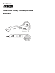
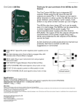
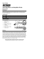
User's Guide
Tone Generator and Amplifier Probe
Model 40180
Introduction
Congratulations on your purchase of Extech’s Model 40180. This tone generator and
amplifier probe set is used to quickly trace and identify cables or wires within a group and
also check the operation of phone lines. With proper use and care, this meter will provide
many years of reliable service.
Specifications
Power
Tone output
Dimensions
Weight
9V battery (tone generator and probe (1 each))
1kHz, 6V square wave (approximately)
Probe:9x2.25x1(228x57x25.4mm),Generator:2.5x2.5x1.5”(63.5x63.5x38.1mm)
0.6lb (272gm)
Meter Description
1.
2.
3.
4.
5.
6.
7.
8.
9.
Power switch
Modular connectors
Test leads
Battery compartment (rear)
Probe tip
Volume/Sensitivity control
Power button
Battery compartment (rear)
Headphone jack
Warranty
EXTECH INSTRUMENTS CORPORATION warrants this instrument to be free of defects in parts and
workmanship for one year from date of shipment (a six month limited warranty applies on sensors and cables). If it
should become necessary to return the instrument for service during or beyond the warranty period, contact the
Customer Service Department at (781) 890-7440 ext. 210 for authorization. A Return Authorization (RA) number
must be issued before any product is returned to Extech. The sender is responsible for shipping charges, freight,
insurance and proper packaging to prevent damage in transit. This warranty does not apply to defects resulting
from action of the user such as misuse, improper wiring, operation outside of specification, improper maintenance
or repair, or unauthorized modification. Extech specifically disclaims any implied warranties or merchantability or
fitness for a specific purpose and will not be liable for any direct, indirect, incidental or consequential damages.
Extech's total liability is limited to repair or replacement of the product. The warranty set forth above is inclusive
and no other warranty, whether written or oral, is expressed or implied.
Copyright © 2001 Extech Instruments Corporation. All rights reserved
including the right of reproduction in whole or in part in any form.
Operating Instructions
Cable/Wire tracing
CAUTION: Do not connect the tone generator in the TONE position to any wire or cable
with an active circuit of more than 24VAC.
1. Connect the tone generator to the cable
a) For cables terminated at one end, connect the red alligator clip to a wire and the
black alligator clip to equipment ground
b) For unterminated cables, connect the red alligator clip to one wire and the black
alligator clip to another wire.
c) For cables with modular connectors, plug the RJ11 or RJ45 connectors directly
into the mating cable connectors.
2. Set the tone generator power switch to the TONE position.
3. On the amplifier probe, press and hold the side on/off switch.
4. Hold the insulated probe tip against the wire in question to pick up the signal
generated by the tone generator.
5. Rotate the volume/sensitivity control on the top of the probe for the appropriate level
and sensitivity to identify and trace the wire.
6. The tone will be the loudest on the wires connected to the tone generator.
Note: RJ11 tests are performed on one pair only and RJ45 tests are performed on pins 4
and 5.
Note: A headphone jack is located on the bottom of the probe.
Identifying telephone cable Tip and Ring – Using Alligator Clips
1. Switch the tone generator to the OFF position
2. Connect the red test lead to one line and the black lead to the other line.
3. The LED color indicates the connection to the RED test lead as:
GREEN = Ring side,
RED = Tip side.
Identifying telephone cable Tip and Ring – Using the RJ-11 or RJ-45 Connectors
1. Switch the tone generator to the OFF position
2. Connect the RJ-11 or RJ-45 connector mating cable connector.
3. The LED color indicates the condition of the telephone jack wiring.
GREEN = Jack wired properly,
RED = Jack wired with reversed polarity.
Identifying telephone cable Line Condition
1. Switch the tone generator to the OFF position
2. Connect the red test lead to the RING side and the black test lead to the TIP side.
3. The LED will indicate line condition by:
GREEN = CLEAR , OFF = BUSY, Flickering YELLOW = RINGING
4. Switch the tone generator power switch to CONT to terminate the call.
Continuity testing
CAUTION: Do not connect the tone generator in the CONT position to any wire or cable
with an active circuit of more than 24VAC.
1. Connect the test leads to the wire pair under test.
2. Switch the tone generator to the CONT position.
3. The LED will glow bright GREEN for a low resistance or continuity. The LED will glow
less brightly as the resistance increases and will extinguish at approximately 10,000
ohms.
Tone selection
The output of the tone generator can be set to continuous or wobble. To change the type
of output, change the tone type switch position (located in the battery compartment)
Battery replacement
Install a new battery by removing the battery cover as indicated in the meter description
diagram.
2
40180
V1.1 4/01