1
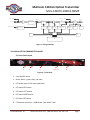
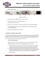
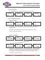
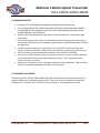
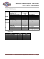
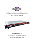
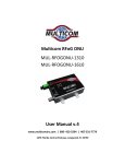
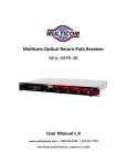
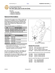
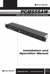
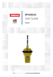
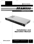
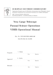
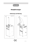
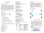
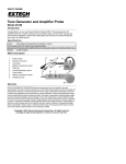
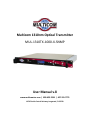
Multicom 1310nm Optical Transmitter
MUL-1310TX-1000-X-SNMP
User Manual v.8
www.multicominc.com | 800-423-2594 | 407-331-7779
1076 Florida Central Parkway, Longwood, FL 32750
Multicom 1310nm Optical Transmitter
MUL-1310TX-1000-X-SNMP
SAFETY NOTIFICATION
The Multicom 1310nm Optical Transmitter is classified as Class 1M per IEC/EN 60825-1/A2:2001. This product complies with
FDA/CDRH, 21 CFR 1040.10 and 1040.11 except for deviations pursuant to Laser Notice No. 50 dated 26 July, 2001.
Viewing the laser output with certain optical instruments (for example, eye loupes, magnifiers and microscopes) within a
distance of 100 mm may pose an eye hazard.
Laser power up to 26 mW at 1310 nm could be accessible if optical connector is open or fiber is broken. Lasers are Powered ON
whenever the unit is powered.
CAUTION: Use of controls, adjustments, and procedures other than those specified herein may result in hazardous
laser radiation exposure.
IMPORTANT SAFEGUARDS
Multicom strongly advises you to read the following safety instructions prior to installing and operating this equipment.
•
•
•
•
•
Read These Instructions First – All safety and operating instructions should be read before installing or operating
this equipment.
Retain This Instruction Manual – Safety and operating instructions must be retained for future reference.
Ventilation – Do not block or cover openings in this equipment. These are provided for ventilation and
protection from overheating. Maximum operating ambient temperature is 122°F (50°C).
Power Sources – The Multicom MUL-1310TX-1000-X-SNMP Optical Transmitter must have a grounding
resistance of <4 ohms. All power must be provided via a three wire, grounded power supply and cord. The mains
circuit should be a dedicated, unswitched supply. Keeps the unit away from high voltage or other interference
creating devices such as motors, compressors, etc.
Grounding or Polarization – This equipment is equipped with a polarized AC line plug. This plug will fit into the
power outlet only one way. This is a safety feature. Do not defeat the safety purpose of a polarized plug. This
equipment must installed and grounded per NEC regulations.
CAUTION: For continued protection against risk of fire, replace circuit breakers/fuses (if necessary) with one of
only the same type and rating.
Optical Output Safety: The Optical Transmitter units may emit harmful invisible laser radiation if powered on
and the case is opened or the beam path is exposed.
© 2012 Multicom, Inc.
www.multicominc.com (800) 423-2594 | 407-331-7779
Page 2
Multicom 1310nm Optical Transmitter
MUL-1310TX-1000-X-SNMP
Table of Contents
1.0 PRODUCT DESCRIPTION
2.0 PRODUCT FEATURES
3.0 1310nm OPTICAL TRANSMITTER LAYOUT
3.1 Front of Unit
3.2 Rear of Unit
4.0 CONTROLS, INDICATORS, AND ALARMS
4.1 Front Panel Operations
4.2 Start-up Main Menu
4.3 Unit Configuration Instructions
5.0 OPERATION NOTICE
6.0 WARRANTY AND REPAIR
7.0 PRODUCT SPECIFICATIONS
© 2012 Multicom, Inc.
www.multicominc.com (800) 423-2594 | 407-331-7779
Page 3
Multicom 1310nm Optical Transmitter
MUL-1310TX-1000-X-SNMP
1.0 PRODUCT DESCRIPTION
Multicom’s MUL-1310TX-1000-X-SNMP Direct Modulated Transmitter delivers high
performance signal transmission of NTSC, PAL, ATC, QAM, and related digital
information for CATV and/or telephony applications. It is based upon custom highlinearity optically isolated DFB (Distributed Feedback) lasers, specifically designed for
multi-channel AM video applications. The built-in control circuits provide an
exceptionally low noise and inter-modulation characteristics. Automatic output power
control, coupled with temperature stabilization provided by a thermoelectric cooler
ensures maximum performance and longer laser life.
All internal laser parameters and monitoring functions are under microprocessor
control: the front panel displays status information related to laser operation,
temperatures, and RF input.
The units are packaged in slim 1.75-inch high (1RU), 19-inch aluminum rack-mounted
enclosures.
2.0 PRODUCT FEATURES
•
Transmits NTSC, PAL, ATC, and related digital information for CATV and/or telephony
applications
•
Available in a variety of output levels
•
High linearity, optically isolated, distributed AM feedback DFB laser.
•
54-1000MHz RF input bandwidth
•
Front panel laser diode and rear panel RF input test points (-20dB)
•
Operation wavelength: 1310nm
•
Low RF drive levels enabled due to built-in RF amplifier and Automatic Gain Control
•
Microprocessor-controlled diagnostics, front panel LCD display and controls
•
Integrated SNMP network interface, functional on units with optional S/W loading
•
Power supplies optional in VDC
© 2012 Multicom, Inc.
www.multicominc.com (800) 423-2594 | 407-331-7779
Page 4
Multicom 1310nm Optical Transmitter
MUL-1310TX-1000-X-SNMP
Input TEST
RF Input
Signal Mixed
Incentive TEST
Mixed
Electric
ATT
Frequence
Response ADJ
Frequence
Response ADJ
AGC
Pre
Distortion
RF Power
Detect
RF
Cut-off
Optical
Out
DFB
Laser
Laser
parameter
Incentive power
detection
MPU
APC
ATC
Key
Unit
NEII
LCD
Figure 1 – Design Concept
3.0 1310nm OPTICAL TRANSMITTER LAYOUT
3.1 Front Panel Layout
1
3
2
4, 5, 6, 7
8
Figure 2 – Front Panel
1. Laser On/Off switch
2. Status Alarm – green: okay, red: alert
3. LCD screen (see 4.3 for menu operation)
4. LCD menu ESC button
5. LCD menu LEFT button
6. LCD menu RIGHT button
7. LCD menu SET button
8. F-Connector test point – 20dB below “laser diode” level
© 2012 Multicom, Inc.
www.multicominc.com (800) 423-2594 | 407-331-7779
Page 5
Multicom 1310nm Optical Transmitter
MUL-1310TX-1000-X-SNMP
3.2 Rear Panel Layout
1
2
3
4
5
6
Figure 3 - Rear Panel
1. RF Test Input Port – 20dB below “main-port input” level
2. RF Main Input Port, for 1GHz broadcast signals
3. Fiber Optic SC/APC Connection
4. RS232 Port, only functional on units with optional factory installed SNMP software
5. LAN Port/SNMP Network Interface, only functional on units with optional factory
installed SNMP software
6. Power Receptacle with ON/OFF flip switch
4.0 CONTROLS, INDICATORS, AND ALARMS
This section of the manual gives an overview of the available menus in the MUL-1310TX-1000X-SNMP series Optical Transmitter. All instructions in section 4 refer to the image of the front
panel (Fig 1). The user scrolls through the menus using the push buttons found on the front
panel, these are located just to the right of the LCD screen.
4.1 Front Panel Operations
When the status LED indicator showing green, the unit is working properly; red LED
indicates that the specific function is not working properly or set to off.
A. With the power source turned on (power switches are located at the rear of the
unit) and the unit working properly, the digital panel will display MULTICOM, INC.
and the model number on the second line. The Laser LED alarm (2) will be red.
B. In order to protect the laser, there is a time-delay function. After turning the laser
on with the front panel “Laser On” switch, the laser will start to operate after about
2 seconds. The laser LED will turn from red to green and the LCD display will
become brighter.
© 2012 Multicom, Inc.
www.multicominc.com (800) 423-2594 | 407-331-7779
Page 6
Multicom 1310nm Optical Transmitter
MUL-1310TX-1000-X-SNMP
4.2 Start-up Main Menu
Press LEFT/RIGHT button to scroll through the menu sequence below.
----- SYS INFO ------
--- PARAMETER ---
------ SETTING ------
---- THRESHOLD ---
PRESS
PRESS
PRESS
PRESS
[SET]
[SET]
[SET]
[SET]
4.3 Unit Configuration Instructions
Menu # 1 – SYS INFO
^ PN
^ SN
^ VER
^ IP
MUL-13TX-1G-XX
YYYYMMXXXXXX
FW11011A11206
192.168. 0. 1
Displays part number, serial number, software version and IP address. Read for
information only.
IP address is set by Telnet under username: sysadmin and password: admin.
Press ESC to go up one menu layer.
Menu # 2 – PARAMTER
^ OP OUT
^ TEMP
^ AGC LV
^ BIAS
10.2dBm NORMAL
25.0oC NORMAL
14.8dBm NORMAL
80mA
^ TCI
^ +24V
^ +5V
^ -5V
10.2dBm NORMAL
23.5V
NORMAL
4.9V
NORMAL
-5.1V
NORMAL
NORMAL
Displays optical output power, unit temperature, AGC (automatic gain control) level,
bias current, TCI, and +24V, +5V and -5V power levels. Read for information only. If
any parameter is outside NORMAL range, the display will show HIGH or LOW.
Press ESC to go up one menu layer.
© 2012 Multicom, Inc.
www.multicominc.com (800) 423-2594 | 407-331-7779
Page 7
Multicom 1310nm Optical Transmitter
MUL-1310TX-1000-X-SNMP
Menu # 3 – SETTING
^ AGC/MGC STATUS
^ BUZZER STATUS
AGC
OFF
^^ SET AGC/MGC
^^ SET BUZZER
TO: <AGC>
TO: <OFF>
AGC is set as default mode. Only select the MGC mode if:
•
•
•
Your application has a desired variation of the input level to be passed onto the
receive end of your link
Your application has an input that is too high a level or too low a level to allow AGC
to control it
In MGC mode, the attention level is adjustable between -6.0dB to +10.0dB in
incremental of 0.2dB steps, by pressing LEFT or RIGHT buttons
Buzzer is set OFF in default mode. Set it ON or OFF when there is an alarm
Menu # 4 – THRESHOLD
^ THLD OP OUT
^ THLD TEMP
^ THLD AGC LV
^ THLD BIAS
H: 10.8, L: 9.0dBm
H: 27.0, L: 21.0oC
H: 16, L: 14dBmV
H: 100, L: 30mA
^ THLD TCI
^ THLD +24V
^ THLD +5V
^ THLD -5V
H: 1.2, L: -1.2A
H: 25.5, L: 22.0V
H: 6.0, L: 4.5V
H: -4.5, L: -5.5V
Displays status of factory default high/low threshold levels of monitoring
parameters – optical output power, unit temperature, AGC (automatic gain control)
level, bias current, TCI, and +24V, +5V and -5V power levels. Read for information
only.
Press ESC to go up one menu layer.
© 2012 Multicom, Inc.
www.multicominc.com (800) 423-2594 | 407-331-7779
Page 8
Multicom 1310nm Optical Transmitter
MUL-1310TX-1000-X-SNMP
5.0 OPERATION NOTICE
•
•
•
•
•
•
•
•
Changes to IP and RF Mode settings will be retained on power down/up.
Use only Single Mode Fiber (SMF) optic cable (9/125µM). Multi-Mode Fiber (MMF) is
incompatible with the equipment and will result in unacceptable performance and
possible damage to the equipment.
All fiber splices should be fusion-type splices. Avoid mechanical or compression type
connections.
For optimum performance, fiber runs should be made directly from the transmitter to
the receiver. Minimize the use of adapters, patch panels, and additional points of failure
and signal loss.
In order to ensure return loss is maximum, use only SC/APC connectors. Clean and
inspect connectors and fiber endfaces prior to installation, and every plug in/out cycle.
Use only industry approved methods, materials, and solutions for cleaning.
Do not turn on the transmitter alone or without a protector cover at the unit connector
end, otherwise the laser can do harm, especially to eyes. This is especially critical
because the laser is invisible.
Always turn off the laser prior to making connections to the transmitter. Failure to do so
may cause irreparable damage to the laser and transmitter.
6.0 WARRANTY AND REPAIR
The Multicom MUL-1310TX-1000-X-SNMP Optical Transmitter has a one year warranty and is
subject to Multicom’s standard warranty terms. There are no user serviceable components
inside the unit. The warranty is void if the unit is opened or is damaged due to misuse.
© 2012 Multicom, Inc.
www.multicominc.com (800) 423-2594 | 407-331-7779
Page 9
Multicom 1310nm Optical Transmitter
MUL-1310TX-1000-X-SNMP
7.0 PRODUCT SPECIFICATIONS
General
Optical
RF
Specifications
Operating temp. (ºC)
Storage temp. (ºC)
Operating relative humidity (%)
Power supply (Volt AC)
Power consumption (W)
Size (WxDxH in inches)
Interface port
Wavelength (nm)
Output power (dBm)
Optical connector
RF bandwidth (MHz)
Input level (dBmV)
Flatness (dB)
Return loss (dB)
RF connector (main input)
CSO (dB)
CTB (dB)
Values
0 – 50
-40 – 85
5 – 95
100 – 240
25
19x14.25x1.75
RJ45, RS232
1300 – 1320
8 – 14
SC/APC
45 – 1000
15 – 25
-0.75 – +0.75
16
F type
-60
-65
Notes
32 – 122 ºF
Non-condensing
Depending on model
AGC
75Ω impedance
79 channel load, back to
back at 0dBm receive power
Product Series
Part#
MUL-1310TX-1000-8-SNMP
MUL-1310TX-1000-10-SNMP
MUL-1310TX-1000-12-SNMP
MUL-1310TX-1000-13-SNMP
MUL-1310TX-1000-14-SNMP
© 2012 Multicom, Inc.
Output
8 dB
10 dB
12 dB
13 dB
14 dB
CNR
≥52 dB
≥52 dB
≥52 dB
≥52 dB
≥52 dB
www.multicominc.com (800) 423-2594 | 407-331-7779
Page 10