1
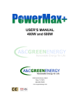
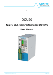
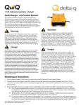
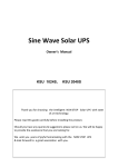
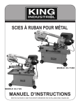
WINDMAX Green Energy
www.magnet4less.com
Green Power for Less!
WINDMAX H Series Wind Turbine
USER’S MANUAL
Windmax-H5 & Windmax-H8
Introduction
WINDMAX-H series wind turbine system is the most advanced and efficient system we
build. The WINDMAX-H series is CE and ISO certified.
WINDMAX-H series wind turbine system features:
Patented aerofoil blade design makes the system run much more efficient, rotor
blades are made with the latest advanced thermoplastic engineering and precision
injection molding technology.
The blades have exceptional consistency and aerodynamic outline with a mass
distribution that ensures the rotors operate with nearly no noise and minimal
vibration.
Wind/Solar hybrid controller to work with both wind turbine and solar panels.
Low maintenance cost, Low shipping cost and purchase cost per watt.
Designed for very low winds, begin producing power at 5.2 mph. very low startup/cut-in wind speed and a high coefficient of productivity and is specially
designed to prevent the blades from feathering post stall.
The generator is built using high-performance permanent magnet, so the
alternator is compact and light weight with a high power generating efficiency.
The unique winding and multi pole design reduces the start-up torque of the
alternator that assures the WINDMAX-H can generate electricity at low wind
speed.
Generator casing is precision cast from high strength aluminum to assure a high
quality finish. It is designed for various working conditions such as severe climate,
sand and salt corrosive environments and marine usage.
Truly "worry-free", fully automatic Speed-limitation mechanism
Features Electromagnetic speed limitation and blade over-speed braking
Exquisite set with unmatched power generating performance. It is a great green
power source for the modern living environment.
The system is easy to install; however, it is important that you read this manual
thoroughly prior to installation to assure proper performance and safety.
1. Package Contents
Check the parts listed below with the contents of the box to make sure that you have
everything needed for assembly.
Wind Turbine Components
Wind Generator with Tail fin
Rotor blade
Rotor hub
Front cover
Front cover Stopper
Accessories
Quantity
1
3
1
1
1
Quantity
Bolt M8*30
Flat Washer M8
Nylock Nut M8
Bolt M6*35
Flat washer M6
Nut M16*1.5
Lock Washer M16
Included Sample Tools
M5 Socket Head Wrench
M8 Wrench
M24 Wrench
8
9
9
1
1
1
1
Quantity
1
1
1
2. Assembly
Assemble WINDMAX-H referring to following figures.
Number
1
2
3
4
5
6
7
8
9
10
11
12
2.1
Description
Generator Assembly
Rotor Blade
Rotor Hub
Front Cover
Front Cover Stopper
Bolt M8*30
Flat washer M8
Nylock Nut M8
Bolt M6*35
Flat washer M6
Nut M16*1.5
Lock Washer M16
Quantity
1
3
1
1
1
9
9
9
1
1
1
1
Usage
Fittings
Rotor blades
Front Cover
Generator
Assembly
Mounting the rotor hub
1. Remove the nut lock washer and flat washer from the alternator shaft;
2. Slide the rotor hub onto the alternator shaft and place the flat washer and lock
washer;
3. Thread and tighten the nut. The nut should be tightened to 70-85 Nm.
2.2
Mounting rotor blades
1. Blades are in front of the rotor hub with the flat side facing upwind.
2. Insert three bolts in holes on the hub and blade. Place flat washers on the end of
bolts, thread and tighten nylock self-locking nut. Nuts should be tightened to 8-12
Nm.
2.3
Attaching the spinner
Place the spinner over the center of the hub. Thread the M6*35bolt with lock washer and
flat washer into the screw hole on the alternator shaft and tighten by hex key.
2.4
Mounting the yaw pole
Slide the yaw pole onto the yaw shaft of the head assembly and fastened by four bolts
M8/15 with flat washers and lock washers.
1. Drill through the tower tube to the electric wire
2. Attach the wind turbine head assembly.
3. Assemble the wind turbine rotor hub
4. Attach the wind turbine rotor blades
5. Attach the wind turbine front cover
6. Secure the wind turbine screw cover
3 Siting
Siting is an important but complicated issue for wind power installation. Consulting a
wind energy specialist is recommended if the user is not familiar with wind systems.
Four general rules are listed as below for consideration:
1 There are two basic requirements for a good site: high average wind speed
and low wind turbulence. The higher the average wind speed, the more the
power will WINDMAX-H wind turbine generate. The power available in
the wind goes up with the cube of the wind speed. For example, the power
available in the wind of 5mps speed is nearly twice as of 4mps. The lower
the wind turbulence, the lower the stress the wind turbine will have to
endure. Lower turbulence also results in more power .The zone with high
wind speed but high turbulence is not a desirable site.
2 Install the wind turbine as high as you can. The higher the tower, the
higher the wind speed and the lower the turbulence .The recommended
tower height for the WINDMAX-H is 8 m above ground level without
barriers.
3 Barriers (trees, buildings, etc.) to the flow of wind will produce wakes that
may extend far downwind of the barrier and to a height considerably
above the barrier. These wakes are areas decreased wind speed and
potentially damaging turbulence.
Two rules of thumb:
a. A tower immediately downwind of a building should be at least
twice of the height of the building.
b. A tower should be at least 6 m higher than the highest barrier
within 150m radius.
4. The local and national codes and requirements should be complied with.
4. Tower Recommendations
The WINDMAX-H is designed to withstand a maximum horizontal direction force of
500N mounted on the tower. The tower must be capable of withstanding the wind load.
A guyed steel pipe tower is the most economical method to install a turbine. 1 ½ inch or 2
inch SCH 40 steel pipe is recommended for the WINDMAX-H guyed tower.
The tower should be properly electrically grounded.
Suitable Foundation:
The Construction Method for the tower base is according to the soil conditions at your
tower site.
If the tower site is located on solid rock, it just needs to level off.
If the tower site is located on the soft soil, the ground of 0.8m in diameter must need to
tamp and it can prevent the foundation from caving in.
If the tower site is located on the loose sand, it needs to dig a hole 0.8m in diameter and
1.5m deep, and then bury a clay pan 60cm deep and tamp the clay pan, and cover
concrete of 20cm deep on the clay pan. Once the concrete has set it should be buried
before use.
Construction Specification Layout of Tower for Wind Turbine-Guyed Tower
The tower base pad layout
Recommended Tower Specifications
Height of Tower
8 Meter
6 Meter
Dimension of
Tower Base
Diameter
Diameter
Windmax-H5
Windmax H8
80 mm
100 mm
60 mm
80 mm
800 mm x 800mm x 200 mm
Wall Thickness
3.5 mm
3.5 mm
Radius of
Guy Wire
4.6 M
4M
5. Cable Wiring
The basic wiring diagram of single WINDMAX-H system is as shown.
1. Regulator Connection: Before erecting the WINDMAX-H tower, connect the
WINDMAX-H to the regulator, and turn the breaker switch on the regulator to the
closed position. After erecting, make sure that batteries are connected tightly and
correctly with the regulator, and then turn the breaker switch to open position.
2. The electric circuit breaker on the regulator protects the batteries in case of
accidental shorts.
3. WINDMAX-H system supplied with solar & wind hybrid controller.
4. The battery capacity is subject to client’s requirement, but a 100-150AH/12V
battery is recommended for a single WINDMAX-H System.
5. Undersized cables will cause energy loss (voltage drop) to the system. The larger
the cable size, the smaller the energy loss. However, larger size cables will be
more costly.
6. The negative pole of the battery should be properly grounded.
The following cable sizes are recommended for the WINDMAX-H system:
Distance from
WINDMAX to
battery (meter)
< 50
50-100
100-150
Cable Size
(mm2)
4
6
10
6. Maintenance
The WINDMAX-H is a very reliable set and is designed to run for long periods at severe
conditions without any maintenance. But routine checking of system tower and cable
wiring system is suggested to maintain the reliability and performance of the system.
1. Check guy rope tension and tighten if needed, especially after storms. During first
three months after erecting the tower, periodic inspection should be carried out.
2. Check all electrical connections to make sure they are properly connected,
tightened and free from corrosion.
3. Maintain batteries according to battery manual.
7. Safety Precautions
The WINDMAX-H is designed with your personal safety as the first priority. However,
there are still some inherent dangers involved in the electrical/mechanical equipment.
Safety must be the priority concern during installation of the system.
7.1 Choose a calm day to erect the tower.
7.2 Undersized wires or bad connections should be avoided as they will often result in
overheating and potentially cause electrical fire.
7.3 Never approach an operating turbine during strong winds or during thunderstorms.
8. Technical specifications
Model
Rotor diameter
Start up wind speed
Cut-in wind speed
Rated Outputs
Survival wind speed
Solar energy input
Battery Voltage
WINDMAX-H5
1.4m (4.6 Feet)
2.3m/s or 5.2 mph
3.0 m/s or 6.7 mph
485W @ 31 mph, 400W @ 26 mph
60 m/s
12VDC, 100W
12VDC
Model
Rotor diameter
Start up wind speed
Cut-in wind speed
Rated Outputs
Survival wind speed
Solar energy input
BatteryVoltage
WINDMAX-H8
1.8m (5.9 Feet)
2.3m/s or 5.2 mph
3.0 m/s or 6.7 mph
775W @ 31 mph, 600W @ 26 mph
60 m/s
12VDC, 300W
24 VDC
9. Power curves
WINDMAX-H5:
WINDAMX-H8