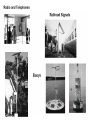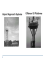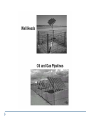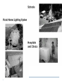
1
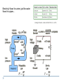
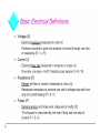
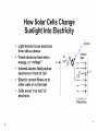
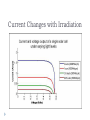
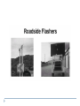
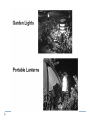
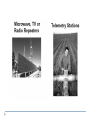
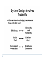
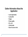
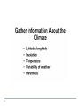
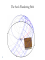
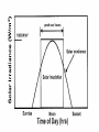
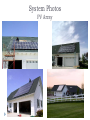
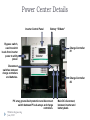
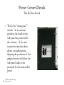
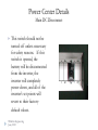
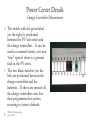
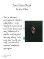
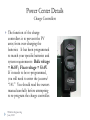
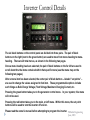
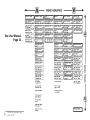
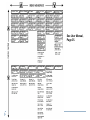
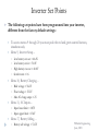
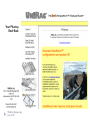
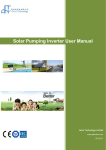
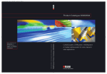
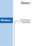
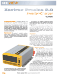
ELTR 1223 Survey of Renewable Energy Technology Unit 6 Intro to Solar-PV REEC 120 Sustainability and Renewable Energy Source: Use Policy This material was developed by Timothy J. Wilhelm, P.E., Kankakee Community College, with funding from the National Science Foundation as part of ATE Grant No. 0802786. Additional changes were incorporated for REED 120 with funding from the Trade Adjustment Assistance Community College and Career Training (TAACCCT) SGA/DFA PY 10-03 All materials in this presentation are designed and intended for educational use, only. They may not be used for any publication or commercial purposes. Source: Author, Editors/Reviewers Author: Timothy J. Wilhelm, P.E., Kankakee Community College Editors/Modifier: Chris Miller Heartland Community College Source: Objectives Students will be able to describe, in very simple terms, the meaning of the “photovoltaic effect.” Students will be able to list, and briefly describe (in very simple terms), at least three different application modes for solar-PV technology. Students will be able to describe, in very simple terms, three different kinds of solar-PV cell technology. Source: Objectives Students will be able to describe, in very simple terms, the general construction of a solarphotovoltaic module, and how its series-string construction impacts the requirements for properly positioning/locating/mounting the module. Students will be able to discuss and describe, in very simple terms, how a solar-photovoltaic module reacts to temperature extremes – how extreme heat and cold affect its output. Source: A Brief Introduction to Electricity Solar-PV is an Electrical Technology Electricity flows thru wires just like water flows thru pipes… Voltage is the pressure that pushes electric current thru a wire, just as hydraulic pressure forces water to flow thru a pipe. Just like water thru a pipe, electric current flows thru wire… D.C A.C. Conductors have loosely held, or free electrons… Insulators have tightly held electrons… Source: http://www.energyquest.ca.gov/story/images/chap02_wire_2007.gif The thinner the pipe the greater the resistance and the less the water flow…and vice versa The thinner the wire the greater the resistance and the less the current…and vice versa It’s important to know the difference between electric power and electrical energy! PV The Photovoltaic Effect The Photovoltaic Effect What is it? The direct conversion of sunlight into electricity. When was it discovered? When Abraham Lincoln was President of the U.S.A.! 1839, by Edmond Becquerel History 1839 – Edmond Becquerel, 19 year-old discovered the photovoltaic effect 1873 – Willoughby Smith discovered the photoconductive effect (selenium) 1883 – Charles Fritz made first “solid-state” solar cell (transparent gold layer over selenium) 1954 – Bell labs develop first “practical” solar cell 1963 – Wilhelm spent all his paper route savings on a small, single Bell Labs solar cell for his Jr. High science fair! Current Changes with Irradiation Voltage Changes with Temperature PV How are Solar Cells Made? How are Solar Cells Made? The Doping Process Adding an impurity to silicon in order to change its internal properties. Because the production of energy depends on the separation of positive and negative charges, silicon must be modified. The charge carrying behavior of the crystal silicon is changed. Silicon has 4 valence electrons (electrons on the outer shell). To create an impurity between the silicon bonds, boron and phosphorus are added through a heating/vapor process. Silicon is very stable in pure crystal form. Boron’s Job (Bottom of Cell) Boron has 3 valence electrons. When boron is introduced a hole or electron vacancy is present. The hole is like a positive charge because it attracts electrons. This type of silicon is called P-type due to its positive charge. Acceptor dopant. Phosphorus’ Job (top of Cell) Phosphorus has 5 valence electrons. Phosphorus adds an extra electron. The extra electron causes a negative charge. This type of silicon is called N-type due to its negative charge. Donor dopant. 5 valence electrons How are Solar Cells Made? Here is a model of the typical solar cell. Notice the split between the two types of silicon. Source: http://static.squidoo.com/resize/squidoo_images/250/draft_lens9199701module81408401photo_1264529133photo_cells.png PV What can you do with only 0.5V?!?! Solar Cells can be connected in series strings to increase circuit voltage. Cell bottoms can be solid/opaque. Cell tops have to balance connectivity and light transmission! Definitions: PV Module Module: A group of PV cells connected in series and/or parallel and encapsulated in an environmentally protective laminate. Solarex MSX60 60 watt polycrystalline Siemens SP75 75 watt single crystal Definitions: PV Panel Panel: A group of modules that is the basic building block of a PV array. Definitions: PV Array Array: A group of panels that comprises the complete PV generating unit. Types of Solar Cells (silicon based) Source: http://www.rise.org.au/info/Tech/pv/image001.jpg Solar cells are made as: single crystal wafers, poly-crystalline wafers, or thin-film technology. Single Wafer: sliced to the millimeter from a large single crystal ingot. Very expensive, but the silicon is much purer and therefore more efficient. Solar Cell Types Cont’d Polycrystalline Wafers: made by a casting process in which molten silicon is poured into a mould. It is allowed to set, and then cut into wafers. Not as energy efficient. About half the silicon is lost to dust in the cutting process. Thin-Film Technology: (amorphous silicon) made by depositing silicon onto substrate from a reactive gas. Substrates are normally glass or plastic. Thin film has ease of deposition, low cost, is mass producible, and suitable for large applications. Reliability of Solar Cells Most solar-PV modules carry a manufacturer’s warranty of 20 years, or more. Solar cells are very durable. Right: shows the decreasing cost of solar revolution. http://www.acre.murdoch.edu.au/refiles/pv/text.html Future Prospects Solar cell manufacturing has become a growing industry. Demand for cells is increasing. Much Japanese/Australian/Chinese/Indian development. PV Solar-PV Applications PV Applications Corrosion Protection Electric Fences Remote Lighting Telecommunications Solar powered water pumping. Water treatment. Source: http://www.mercadolibre.com.ve/jm/img?s=MLV&f=6934475_8041.jpg&v=P Different PV applications have different circumstances and different requirements… Near Utility Power, or Remote? Daytime Only, or Anytime? Photovoltaic Only, or Hybrid Generation? Centralized or Decentralized? Batteries/Stand-Alone, or Utility-Tied/No Batteries? Simple PV Power System Overview Considerations and Examples The Sun’s Wandering Path Cartesian Coordinate Sun Map Source: http://www.mysundial.ca/tsp/images/sun_chart_sundials.jpg PV Types of Solar-PV Systems PV System Modes Direct-Power of DC Loads Simple Utility-tied Simple, battery-based, Stand-Alone Stand-Alone / Utility-Tied Hybrid Hybrid System Inputs… PV with Wind PV with GenSet Direct PV-Powered Loads Source: http://www.rise.org.au/info/Applic/Solarpump/image002.jpg Simple Utility-Tied System Source: http://www.rhoduselectric.com/images/10-14-08/Solar_Electric_Systems.jpg Simple Stand-Alone System Source: http://homepower.com/images/basics/Basics_SolarElect_OffGridFlow.jpg Grid-Tied with Batteries Source: http://homepower.com/images/basics/Basics_SolarElect_GridBBFlow.jpg PV System Electrical Design: Common Problem Areas Insufficient conductor ampacity and insulation Excessive voltage drop Unsafe wiring methods Lack of or improper placement of overcurrent protection and disconnect devices Use of unlisted, or improper application of listed equipment (e.g. ac in dc use) Lack of or improper equipment or system grounding Unsafe installation and use of batteries PV An Example Solar-PV System – Report to Client Final Project Report To: Alan and Susan Xxxxx Your 5KW Solar-Photovoltaic Power System Wilhelm Engineering June, 2003 General System Description PV array consists of 48, ShellSolar SM-110, 110 watt photovoltaic modules. PV array roof-mounting rack is the UniRack SolarMount system. The PV series-string combiner is from OutbackPower. The string combiner is located in the attic, above the garage. The entire PV array is divided into two sub-arrays. Each sub-array is controlled by an OutbackPower MX60 charge controller. The battery bank consists of eight Concorde PVX-258, sealed, AGM batteries. The batteries are housed in a cabinet made by OutbackPower. The system inverter is a Xantrex SW5548. The inverter, the charge controllers, the PV ground-fault protection, the main DC disconnect and OCP, the AC bypass switch, and other necessary disconnects and metering are all mounted and assembled on an OutbackPower power panel. 240 VAC is provided for the well pump via a Xantrex T240 autotransformer. Wilhelm Engineering June, 2003 System Photos PV mounting rack All mounting feet are lag-screwed into roof trusses and are thoroughly sealed with polyurethane roof sealant. All rails are carefully spaced and aligned to allow proper mounting of the PV modules. Wilhelm Engineering June, 2003 System Photos PV Array Wilhelm Engineering June, 2003 System Photos PV array details PV series strings penetrate into the attic through flashed and sealed, outdoor-rated boxes. All PV-module frames are bonded together with tinned and braided grounding straps, attached with stainless-steel tek screws. The entire frame and rack system is tied into the house lightning protection system with 4AWG stranded copper ground wire. Wilhelm Engineering June, 2003 System Photos PV combiner box The PV series-string combiner is located in the attic, above the garage, and directly below the PV array. The string combiner includes overcurrent protection and disconnect means for each of the 12 series strings of PV modules. Six series strings of PV modules are combined into a single subarray. There are two sub-arrays of 24 modules each. Wilhelm Engineering June, 2003 System Photos Power Control Center The Power Panel contains the charge controllers, inverter, gridtie interface, disconnects, etc. The sealed batteries are housed in the vented steel cabinet below the Power Panel. Wilhelm Engineering June, 2003 Note the DC lightningsurge arrestors hidden behind the charge controllers. Power Center Details Inverter Control Panel By-pass switch, used to switch loads from inverter power to utility power. Battery “E-Meter” Charge Controller #1 Inverter Disconnect switches between charge controllers and batteries. PV array ground-fault protection and disconnect switch between PV sub-arrays and charge controllers. Wilhelm Engineering June, 2003 Charge Controller #2 Main DC disconnect, between inverter and battery bank. Power Center Details The By-Pass Switch This is the “emergency” switch. In its normal position, the loads in the sub-panel are powered by the inverter. If for any reason the inverter shuts down, or malfunctions, flipping the positions of the ganged switch will allow the sub-panel loads to be powered by the main utility panel. Wilhelm Engineering June, 2003 Power Center Details Main DC Disconnect This switch should not be turned off unless necessary for safety reasons. If this switch is opened, the battery will be disconnected from the inverter, the inverter will completely power down, and all of the inverter’s set points will revert to their factory- default values. Wilhelm Engineering June, 2003 Power Center Details Charge Controller Disconnects The switch with the green label (on the right) is positioned between the PV sub-arrays and the charge controllers. It can be used as a manual switch, or it may “trip” open if there is a ground fault in the PV array. The two black switches (on the left) are positioned between the charge controllers and the batteries. If these are turned off, the charge controllers may lose their programmed set-points, reverting to factory defaults. Wilhelm Engineering June, 2003 Power Center Details The Battery E-Meter This is the main batterymonitoring meter. It defaults to reading the battery voltage. When full, the batteries will read near 56.5 volts. During a power outage, the batteries will be drained of stored energy, and their voltage will drop. As the voltage drops toward 48 volts, energy conservation will be necessary to extend inverter operating time. Wilhelm Engineering June, 2003 Power Center Details Charge Controllers The function of the charge controllers is to prevent the PV array from over-charging the batteries. It has been programmed to match your specific batteries and system requirements: Bulk voltage = 56.8V; Float voltage = 53.4V. If it needs to be re-programmed, you will need to enter the password “141.” You should read the owners manual carefully before attempting to re-program the charge controller. Wilhelm Engineering June, 2003 Power Center Details Inverter Controls The inverter is actually a microprocessor-controlled inverter/charger. The operating parameters of the inverter are “programmed” via the control pad on the face of the inverter. The inverter has been programmed to match your system requirements. If it looses DC power, and reverts to factory defaults, it will need to be re-programmed with the proper values. Wilhelm Engineering June, 2003 Source: http://www.magnet4less.com/images/sw_image.jpg Inverter Control Details The six black buttons on the control panel are divided into three pairs. The pair of black buttons on the right (next to the green button) are used to move from menu-heading to menuheading. There are 20 total menus, as shown in the following two pages. Once a menu heading has been selected, the pair of black buttons on the far left are used to scroll down thru the items contained within that specific menu (see the menu map on the following two pages). After a menu item has been selected, the center pair of black buttons – labeled “set points” – are used to change the values assigned to that item. These programmable options include such things as Bulk Charge Voltage, Float Voltage, Maximum Charging Current, etc. Pressing the green button takes you to the generator control menu. In your system, this menu will not be used. Pressing the red button takes you to the main, on/off menu. Within this menu, the set point buttons will be used to turn the inverter off and on. Please read the owner’s manual before attempting to program the inverter. Wilhelm Engineering June, 2003 See User Manual, Page 34. Wilhelm Engineering June, 2003 See User Manual, Page 35. Wilhelm Engineering June, 2003 Inverter Set Points The following set points have been programmed into your inverter, different from the factory default settings: To access menus 9 through 20 you must push the red and green control buttons, simultaneously. Menu 9, Inverter Setup… Menu 10, Battery Charging… Bulk voltage = 56.6V Float voltage = 53.2V Max AC charge amps = 25 Menu 11, AC Inputs… Low battery cut out = 46.4V Low battery cut in = 51.0V High battery cut out = 60.0V Search watts = 16 Input lower limit = 105V Input upper limit = 136V Menu 17, Battery Selling… Battery sell voltage = 53.2V Wilhelm Engineering June, 2003 Manufacturer and Warranty Information All of the major components of your system are warranted by their manufacturers. Manufacturer warranty and contact information can be found in the equipment user manuals. For your convenience, contact information is also on the following pages. Your system was sold and installed by: Wilhelm Engineering, 149 Sun Street, Stelle, IL 60919; 815256-2284 Wilhelm Engineering June, 2003 Your Inverter and Transformer Wilhelm Engineering June, 2003 Your Photovoltaic Modules Wilhelm Engineering June, 2003 Your PV-array Roof Rack Wilhelm Engineering June, 2003 Your Charge Controllers, Power Center, and Battery Cabinet Wilhelm Engineering June, 2003 Next Week… Re-visit solar-PV A little review A little more detail Electrical Generator Technology Converting mechanical energy into electrical energy Finis Source: http://www.cosmiclight.com/imagegalleries/images/space/sun-sumer.jpg