1
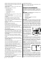
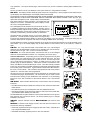
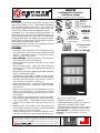
July 17, 2000 DN-713 A-100 AM2020 Intelligent Fire Detection and Alarm System Section: Intelligent Fire Alarm Control Panels GENERAL The AM2020 is an intelligent, addressable, fire alarm control panel with the capacity for up to 1,980 individually identifiable and controllable detection/control points. The modular hardware design and easy-to-define system operation software allows the user to easily configure the AM2020 in the field. The AM2020 is UL Listed under the following standards: UL864 Control Units for Fire Protective Signaling Systems; UL1076 Proprietary Burglar Alarm Units; and UL-1610 Central Station Burglar Alarm Units. The AM2020 also meets the requirements of NFPA 72 Local, Auxiliary, Remote Station, Proprietary, and Emergency Voice/Alarm fire systems. CS118 MEA S635 S5511 289-91-E Approved (Also approved for Automatic Release & Preaction Deluge) Addressable/intelligent detectors help firefighting personnel quickly locate a fire during its early stages. BSA 578-81-SA U.S. Coast Guard 161.002/27/1 FEATURES 93/60140 (E1) City of Chicago 0713cov.tif, NFSrev00.wmf Completely field-programmable and configurable from the front panel keypad. No special computer programming skills required. The AM2020 continues to provide fire protection while its program is being edited. NOTIFIRENET interface provides a peer-to-peer highspeed network (see data sheet DN-4644). Upload/download of all program information to a PC-compatible computer. VeriFire software utility create, edit, check, simulate by association, and compare panel databases (Windows® 95/ 98 compatible). SCS-8 smoke control option (NFPA 90A, 92A & B listed) dedicated or non-dedicated systems. Automatic drift compensation of intelligent smoke detectors. Meets the requirements of NFPA Chapter 7 for calibrated test. Automatic system test activates and verifies (17 cycles in a 24-hour period) every detector in the system. Detector sensitivity adjust manual or automatic (day/night). Maintenance alert function automatically warns of contaminated detectors. Walk test with counters per point and identification of two detectors set to same address. Test portions of the system while remainder continues to provide fire protection. Timer to abort walk test. Alarm verification, with verification tally counter, per detector. Also includes a programmable detector verification limit check. Large system capacity: 990 intelligent detectors plus 990 monitor/control modules plus 2,048 annunciator/control points. Multiple two-wire communication loops, each supporting up to 198 intelligent detectors and system modules, wired NFPA Style 4 or Style 6, (or Style 7 with Isolator). Intelligent (Analog) Detectors: Ionization, Photoelectric, Thermal (with or without Rate-of-Rise feature), Multi-Sensor (ion, California State Fire Marshal 7165-0028:141 7170-0028:153 The AM2020 (shown in CAB-C3) photo, heat in same head). Intelligent photoelectric duct detectors. Addressable initiating modules to monitor normally open or normally closed contacts. Addressable dry-contact relay modules and supervised notification appliance circuit modules. NOTIFIRENET is a trademark of NOTIFIER, 1994. Windows® is a registered trademark of Microsoft Corporation. This document is not intended to be used for installation purposes. We try to keep our product information up-to-date and accurate. We cannot cover all specific applications or anticipate all requirements. All specifications are subject to change without notice. For more information, contact NOTIFIER. Phone: (203) 484-7161 FAX: (203) 484-7118 One Fire-Lite Place, Northford, Connecticut 06472 Made in the U.S.A. DN-713 07/17/00 Page 1 of 6 Page 2 of 6 DN-713 07/17/00 Marine agency approved. UDACT Universal Digital Alarm Communicator Transmitter (see UDACT data sheet). PRODUCT LINE INFORMATION The AM2020 may be custom configured to meet the requirements of the particular installation. System size is defined by the number of loop interface boards which are used. Removal, disconnection, or failure of any control panel module is detected and reported by the CPU2020. This module contains and executes all control-by-event programs for specific action due to detection of a fire. 0713cpu2.wmf BE-2020N : The Basic Equipment Package for the AM2020 includes the following: ü One DIA-2020. ü One CPU-2020. ü One ICA-4L. ü One set of miscellaneous hardware. ü One set of cables. ü One manual. CPU-2020: The Central Processing Unit (CPU-2020) is the director of all system communications and operations. The CPU-2020 stores all of the systems operational parameters (which are programmed in the field) in nonvolatile memory. Special software and hardware is used to ensure the integrity of the memory. The CPU2020 also provides a Form-C auxiliary alarm operated contact and a Form-C auxiliary trouble operated contact. Communications with system modules are over a high-speed serial interface. CPU-2020 Such control-by-event programs are held in the nonvolatile programmable memory. The CPU-2020 provides a real-time clock for the date and time annotation of displayed or printed alarm or trouble events. [Position B in the Interconnect Chassis Assembly (ICA-4L). Cabinet location Tier #1 is reserved for the CPU-2020.] ICA-4L: The ICA-4L (interconnect board and chassis assembly) provides the AM2020 with mechanical means to mount the various system boards. The ICA-4L also distributes power and data between the system boards, thus simplifying the construction and wiring of the AM2020 Control Panel. 0713ica4.wmf Modular hardware design with plug-in terminal strips. Multiple microprocessors with degrade operation mode in event of CPU failure. Custom descriptive labels for each system point and software zone. Powerful control-by-event functions: Point and/or zone. AND/OR/NOT function. Time equations. Tracking/latching selections. Pulse timers. Non-alarm points (lower priority) for energy management or lighting functions. Control-by-time functions for time-and-date actuation of outputs. Programmable time delay and pulse functions. User-selectable sensitivity settings per detector. 400-event history log stored in nonvolatile memory with display, scroll, and print. Real-time nonvolatile clock for time-and-date stamp of all events. Multiple assignable passwords. Disable/Enable per addressable device. Status report (types of reports) for all devices in system, including detector sensitivity and verification tally. Software timers for silence inhibit, alarm cutout, and alarm verification. Ground (earth) fault detection. Integral high efficiency power supply with switched regulation, dual-rate charger, and meter option. Includes software timers for use with external NiCad batteries. 80-character alphanumeric, supertwist LCD display with LED backlight. 30-key tactile keypad with full alphabetic capability. Remote CRT terminal option with alarm and trouble counter. Multiple remote 40-column and 80-column printers. 40-column printer utilizes 24 VDC and may be backed up by system battery. Trouble reminder option. XP or XP5 Transponders for large multiplex systems (see XP or XP5 Transponder data sheets). UZC-256 universal zone coder (positive non-interfering successive) module (see UZC-256 data sheet). Remote LCD-80 display of all points. Up to 32 displays per AM2020 (see LCD-80 data sheet). ACM-8R remote relay module extends AM2020 point capacity (see ACM-8R data sheet). ACS serial remote annunciator control systems (see ACS data sheet). Voice and telephone options (see VAM data sheet). Meets requirements of NFPA-72 (Local, Auxiliary, Remote Station, Proprietary, and Emergency Voice/Alarm). Extensive transient protection. Rapid polling algorithm for manual station response in under 5 seconds (first 20 addresses). Pre-Alarm option (programmable) for advanced warning of false alarm conditions. Each ICA can accommodate up to four system ICA-4L boards. Up to three ICA assemblies may be used in one AM2020 control panel. The ICA assemblies work in conjunction with each other to provide location decoding of the Loop Interface Boards, which are to be installed in the various slots in the chassis. In this way, the AM2020 system does not require any jumper cuts or address switch setting to initialize the SLC Loop operations. The system boards plug-in without need for any screws or fasteners, allowing rapid installation and service. The ICA is located on studs, and fastened to the system back box, using hardware included. DIA-2020: The Display Interface Assembly (DIA) consists of a hinged door; a 30-key keypad; an 80-character liquid crystal display with LED backlight; and a Display Interface Board (DIB). The keypad has controls for ACKNOWLEDGE/STEP; SIGNAL SILENCE; SYSTEM RESET; SYSTEM TEST; LAMP TEST; READ STATUS; ALTER STATUS; PROGRAM; SPECIAL FUNCTION; BACK SPACE; ENTER; numeric keys 0-9; plus 0713dia2.wmf alpha enter and alpha keys A-Z. PRIOR, NEXT, and AUTOSTEP keys speed readout of status information. The keypad has LED display for Fire Alarm; Trouble/Security Alarm; Display Trouble; AC Power; and Signals Silenced. The LCD display has 80 characters in two lines of 40 columns. It is capable of displaying all status information, including Type of Event (6 characters); Type of Device (12 characters); Custom Point Label (20 characters); Custom Zone Label (20 characters); Time and Date (14 characters); and Point Number (3 characters). The DIB includes nonvolatile memory for all custom labels and DIA-2020 passwords. The DIB provides integral status and programming functions using interactive Menu displays on either the LCD display or the CRT terminal. All program editing may be achieved without special equipment and without interrupting AM2020 alarm monitoring. The DIA-2020 also includes an EIA-232 interface for the printer and an EIA-485 interface for LCD-80 (terminal mode) annunciators. Up to 32 LCD-80 displays may be daisy-chained on this interface, each up to 6,000 feet (1828.8 m) apart. LIB-400: The Loop Interface Board communicates with up to 198 intelligent detectors and 198 addressable modules over two Signaling Line Circuits (SLCs). LIB-400 pictured at right. See Common LIB Features below. LIB-200A: The Loop Interface Board communicates with up to 99 intelligent Common LIB Features: All operating power, as well as high-speed two-way data communication, are made through a pair of wires called the SLC loop. This SLC loop may be wired to function like a Style 4, or Style 6, circuit. The SLC loop may be up to 12,500 feet (3,810 meters) in length if 12 AWG (3.25 mm²) wire is used (smaller gauge for shorter distances). If the ISO-X module is used between each device, the LIB/SLC can function like a Style 7 circuit. The LIB is normally controlled by the CPU, but includes Local Mode software that will provide degraded operation in the unlikely event of CPU failure. A general alarm bus between LIBs functions in the event of a CPU failure. This bus allows all programmed local mode points to operate as a common alarm when programmed. 0713lib4.wmf detectors and 99 addressable modules over a Signaling Line Circuit (SLC). LIB-400 All wiring from the Loop Interface Board is power limited per UL requirements, and connected with plug-in terminal blocks. All connections may be made to these terminal blocks, allowing for the identification and corrections of any field-wiring faults prior to the final connection of the terminal blocks to the Loop Interface Board. Dual EIA-232 terminal ports (2400 baud, ASCII) for CRT, VGAS, and other EDPlisted devices. Dual EIA-232 printer port for PRN printer and other EDP-listed devices. EIA-485 annunciation ports (20 K baud, ASCII) for ACS annunciators, AMG, Network Interface Board, UDACT, and UZC-256. The SIB-2048A has full optical isolation on the EIA-232 interfaces to avoid groundfault problems with commercial devices. All terminal blocks plug-in to simplify installation and service. 0713sib8.wmf SIB-2048A: Serial Interface Board directs communication with the following interfaces: SIB-2048A SIB-NET: Network interface board for NOTIFIRENET (see separate data provides the following capabilities: Electrically regulated system power supply (24 VDC and 5 VDC). Adequate for a fully configured AM2020 panel. Resettable electrically regulated power for four-wire detectors. 0713mps2.wmf sheet). MPS-24A: The Main Power Supply mounts in the lower left of the cabinet, and MPS-24A DN-713 07/17/00 Page 3 of 6 0713mpm2.wmf MPM-2 5952cov.wmf Non-resettable electrically regulated power (3.0 amps) for notification appliances and/or ACS annunciators. Dual-rate battery charger for gell-cell batteries (up to 25 AH) and NiCad cells up to 32 amp hours (NiCads external). Ground (earth) fault detection with LED display. AC fail/brownout detect and battery switchover, with LED indicator. 120 VAC and 240 VAC (MPS-24AE) options with circuit breaker and IEEE-587 Category A transient protection. PTC power limiting and overload protection on all outputs. Switched regulation for high efficiency and low power dissipation. True battery supervision (disconnect and measure). Battery charger shuts down in alarm for full utilization of system power. Compatible with CHG-120 external 120 amp-hour battery cabinet and charger. Deep battery discharge prevention. MPM-2: Main Power Meter kit for MPS-24A. Includes battery voltage and charging current meters, mounting hardware, and cable. MPS-TR: Trouble relay kit for MPS-24A. Use in conjunction with one MMX-1 or MMX-101 for remote power supply applications. APS-6R lated power for compatible notification appliance circuits. Includes battery input and transfer relay, and overcurrent protection. Mounts on one of four positions on a CHS-4L or CHS-4 chassis. MBT-1: Municipal Box Trip for NFPA 72 applications. Use in conjunction with one CMX module and one A77-716 power supervision relay. CHS-4: Chassis, four position. Use for APS-6R modules. CHS-4L: Chassis, low profile, four position. Use for APS-6R or VAM-2020 mod- 5262chs4.wmf APS-6R: Auxiliary Power Supply (expander). Provides up to 6.0 amperes of regu- CHS-4 ules (see VAM-2020 data sheet). DP-1: Blank Dress Panel. Use to cover unused rows in cabinet, CHS-4/CHS-4L modules within the AM2020 cabinet. Mounts over ICA-4L or unused cabinet row. ACS: Annunciation and Control modules. May be mounted in AM2020 cabinet (see ACS data sheet). 5262dp1.wmf chassis, or LIB board. ADP-4: Annunciator Dress Panel, four position. Use to mount ACS Annunciator DP-1 SCS: Smoke Control System with ON/OFF/AUTO switch controls and LED feedback indications. Meets NFPA smoke control requirements (see SCS data sheet). ACM-8R: Remote relay module with eight form-C contacts. Map any system points or zones to these relays similar to annunciator points (see ACM-8R data sheet). UZC-256: Universal Zone Coder module. Connects to EIA-485 interface. Field programmable with PC computer (see UZC-256 data sheet). LCD-80: Liquid Crystal Display module. Displays all system points and has control switches for ACKNOWLEDGE, SILENCE, and RESET. Up to 32 LCD-80 modules may be used with each AM2020 (see LCD-80 data sheet). CAB-3 Series Cabinets: (see data sheet DN-3549 for cabinet options). RACKMOUNT option (19"): Contact factory. SECURITY EQUIPMENT RKS-S Remote Keyswitch STS-1 Security Tamper Switch. Required for UL 1076/UL 1610 Applications. ELECTRICAL SPECIFICATIONS Primary input power, 120 VAC, 50/60 Hz. Primary input power is 240 VAC, 50/60 Hz as an option. When ordering, add an E to end of 120 VAC model number (example: MPS-24AE). 3.0 ampere, 24 VDC notification circuit power available, expandable in 3.0 ampere steps. Primary AC power supervision with automatic switchover to standby batteries. Supervised standby batteries. Page 4 of 6 DN-713 07/17/00 SYSTEM CAPACITY IPX-751 INTELLIGENT DETECTOR BASES Intelligent/addressable SLC loops ......................... 10 Intelligent detectors per loop ................................... 99 Addressable modules per loop ............................... 99 Intelligent detectors per system ............................ 990 Addressable modules per system ........................ 990 Total addressable/intelligent devices per system ........................................................... 1,980 Total ACS/relay points per system (EIA-485) ..... 2,048 Total points .......................................................... 4,028 Remote ACS addresses per system ...................... 32 Display/relay points per ACS address .................... 64 Remote printers per system ...................................... 6 Remote CRT/keyboard terminals per system .................................................................. 1 Remote CRT/monitor terminals per system ................................................................ 24 CONSTRUCTION The basic equipment for the AM2020 is the BE-2020N, which includes one DIA, one CPU-2020, and one ICA-4L. SIB and LIB boards are then plugged into ICA-4L chassis as needed. Each ICA-4L will accept up to four boards, and uses one tier in the cabinet. Cabinets are wallmounted and are available in one, two, three, or four tiers of usable space. Each cabinet includes space at bottom for the MPS-24A power supply and 25-amp-hour batteries. For example, a six-loop AM2020 system could be ordered as follows: Quantity Advanced multi-criteria detector (ion/photo/ thermal). HPX-751 HARSH photo detector (requires special base). FSD-751P Duct detector, with housing. FSD-751RP Duct detector, with housing and relay. B710LPBP B510BP B710HD B224RB B224BI B501BH B501BHT Standard flanged base, package of ten. Standard flangeless base, package of ten. Base for HPX-751 (HARSH) only. Relay base. Isolator base. Sounder base. Sounder base with temporal sounder. COMPATIBLE ADDRESSABLE DEVICES NBG-12LX FMM-1 FMM-101 FDM-1 FZM-1 FCM-1 FRM-1 XP5-M XP5-C ISO-X Addressable pull station, visible LED. Monitor module. Monitor module, miniature. Monitor module, dual, two independent Class B circuits. Monitor module, two-wire smoke detectors. Control module. Relay module. Transponder, monitor, five addressable Class B circuits. Transponder, control/relay, five addressable Class B circuits. Isolator module. Model Description 1 BE-2020N Base equipment COMPATIBLE DEVICES, EIA-232 Ports 1 ICA-4L Expander chassis CRT Series CRT terminal with keyboard. 2 LIB-400 Loop interface board, 2 loops VS4095/5 40-column, 24 VDC printer. 1 LIB-200A Loop interface board, 1 loop P40-KIT 1 SIB-2048A Serial interface board 1 MPS-24A Power supply VS4095 hardware mounting kit. Allows the VS4095 to be mounted in the AM2020 cabinet (see VS4095 data sheet). 1 DP-1 Blank dress panel 1 CAB-B3 Cabinet PRN Series 80-column printer. COMPATIBLE DEVICES, EIA-485 Ports Orders such as the above can usually be provided directly from finished goods stock. NOTIFIER ships 97% of orders within 48 hours of receipt. ACS Series Remote serial annunciator/control systems (see ACS Series data sheet). AGENCY LISTINGS AND APPROVALS LDM Series Remote custom graphic driver modules (see LDM Series data sheet). See the first page of this product data sheet for listing agencies and file numbers. These listings and approvals apply to the basic AM2020 control panel. In some cases, certain modules may not be listed by certain approval agencies, or listing may be in process. Consult factory for latest listing status. COMPATIBLE INTELLIGENT DETECTORS FSI-751 FSP-751 FSP-751T FST-751 FST-751R Ion detector. Photo detector. Photo detector with fixed thermal element. Thermal detector, fixed. Thermal detector, fixed and rate-of-rise. LCD-80 Remote LCD display (see LCD-80 data sheet). AMG-1/E Audio message generator with coding capability (see Voice Alarm Multiplex 2020 data sheet). ACM-8R Remote relay module (see ACM-8R data sheet). RPT-485W/WF Twisted-pair or fiber-optic EIA-485 signal repeater (see RPT data sheet). SCS Series Smoke control modules (see SCS data sheet). DN-713 07/17/00 Page 5 of 6 INDIVIDUAL POINT DISPLAY/CONTROL The alarm/trouble status of any detector or monitor module, or the ON/OFF/Trouble status of any control module may be displayed on the AM2020 using the ACS series annunciator/control modules (see separate data sheet). The ACS also provide control of output devices and alarm/ trouble display of software zones. They mount in the AM2020 cabinet or in remote cabinets. NON-ENGLISH LANGUAGE Manuals are available, with certain restrictions, for the following languages: French, Spanish, Italian. Contact NOTIFIER for further information. ARCHITECTURAL/ENGINEERING SPECIFICATIONS Specifications are available on CD-ROM with NOTIFIERs SpeciFire software. Contact NOTIFIER for details; http//www.notifier.com. USER MANUAL Installation, programming, and operating information is provided with each AM2020 in a three-ring loose-leaf format manual. Page 6 of 6 DN-713 07/17/00