1
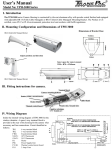
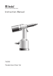
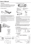
Ⅳ. Wiring diagram
Fig. 4 shows the internal wiring diagram of TPH 4000 for the window demister.
A spare 6 way terminal block is provided at the rear of the enclosure for
camera when necessary and lens connections. Circuit idents as follows:
TB.1
TB.2
FTB.1
FS.1
STAT.1
P.C.B.1
H.1
6 way terminal block
3 way terminal block
Fused terminal block
3 Amp. Fuse
18˚C Thermostat switch
Heater Printed circuit board
Heater,
12/24 VAC
Heater,
230 VAC
Fig.5 Wiring diagram of TPH 4000
ENCLOSRE BASE
TURN OFF AT 28 RISING TEMPERATURE
TURN ON AT 18 DECREASING TEMPERATURE
TB.1
1
2
3
4
5
6
SPARE
STAT.1
N
H.I
E
1 2 3 TB.2
L
CHASSIS EARTH
P.C.B.1
FTB.1 FS.1
COVER EARTH
Fig.6 AC power connection
Shows how to connect the AC power
cord to the FTB.1 connector
AC Power Cord
GND
(Green line)
AC Power Cord
V. Installation Suggestion:
If you plan to install this camera into
a tropical, sea, coastal, saltwater or
corrosive industrial water/moist
environment, please seal each
stainless steel screw and fittings with
a silicon grease compound. This will
help prevent electrolysis corrosive
occurring and extend the lifespan of
the camera and housing.
IMPORTANT NOTE:
1.Disconnect Device: You must disconnect the device from mains supply before changing the
camera or lens inside.
2.Electrical Connections: Only a qualified electrician must make any electrical connections.
GENIE CCTV LTD.
CCTV House,CityPark,Watchmead,Welwyn Garden City,
Hertfordshire,AL7 1LT,United Kingdom
Tel:+44(0)1707330541 Fax:+44(0)1707330543
IP68
TPH 4000 Series
External
Camera
Enclosure
User's Manual