1
ALS-8
PROGRAM
DEVELOPMENT
SYSTEM
OPERATOR'S MANUAL
PROCESSOR TECHNOLOGY CORPORATION
6200 Hollis Street
Emeryville, CA 94608
(415) 652-8080
©Copyright 1977 by Processor Technology Corporation
Manual No.727013
IMPORTANT NOTICE
This copyrighted software product is distributed on an individual
sale basis for the personal use of the original purchaser only. No
license is granted herein to copy, duplicate, sell or otherwise
distribute to any other person, firm or entity. This software
product is copyrighted and all rights are reserved; all forms of the
program are copyrighted by Processor Technology Corporation.
THREE MONTH LIMITED WARRANTY
Processor Technology Corporation warrants this software product to
be free from defects in material and workmanship for a period of
three months from the date originally purchased.
This warranty is made in lieu of any other warranty expressed or
implied and is limited to repair or replacement, at the option of
Processor Technology Corporation, transportation and handling
charges excluded.
To obtain service under the terms of this warranty, the defective
part must be returned, along with a copy of the original bill of
sale, to Processor Technology Corporation within the warranty
period.
The warranty herein extends only to the original purchaser and is
not assignable or transferable and shall not apply to any software
product which has been repaired by anyone other than Processor
Technology Corporation or which may have been subject to alterations, misuse, negligence, or accident, or any unit which may have
had the name altered, defaced or removed.
ALS-8 PROGRAM DEVELOPMENT SYSTEM - OPERATOR'S MANUAL
TABLE OF CONTENTS
CHAPTER I
General Description ..................................1
CHAPTER II
Memory & Program Structure of the ALS-8 ..............4
CHAPTER III Talking to the ALS-8 .................................9
CHAPTER IV
Memory Related Commands .............................12
CHAPTER V
Files and File Commands .............................15
CHAPTER VI
Edit Commands .......................................18
CHAPTER VII I/O Drivers and Commands ............................21
CHAPTER VIII System Commands .....................................23
CHAPTER IX
Command Summary .....................................27
CHAPTER X
The ALS-8 Assembler .................................35
Assembler Error Indications .....................37
Assembly Language Instructions ..................41
Unconditional Transfers .........................48
Conditional Transfers ...........................48
Carry Bit Instructions ..........................49
Subroutine Transfers ............................50
Subroutine Conditional Instructions .............51
16 Bit Operations ...............................54
Stack Operations ................................55
Input/Output Instructions .......................56
Interrupt Related Instructions ..................57
Variable Storage and the NO OP ..................59
SIMULATOR EXTENSION PACKAGE
Operating Manual ................................62
Set Commands ....................................62
Breakpoints and "Real Time Run" Addresses .......65
Input Instructions ..............................66
Output Instructions .............................67
Input/Output Commands ...........................68
optional Simulator Entry Point ..................69
Other SIM-1 Extension Functions .................69
TXT-2 EXTENSION PACKAGE
Operator's Manual ...............................70
Editor ..........................................70
Cursor Positioning Command ......................71
©Copyright 1977 by Processor Technology Corporation
-i-
Manual No. 727013
Table of Contents (cont.)
TXT-2 EXTENSION PACKAGE (cont.)
Screen Scroll Commands ..........................71
Direct File Positioning Commands ................72
File Modification Commands ......................73
Other Commands ..................................74
FIND ............................................74
ESET Command ....................................75
APPENDIX A - Standard System Notes ...............................77
APPENDIX B - ASSI, Assembly from Input Driver ....................80
APPENDIX C - ALS-8 on Cassette and with SOLOS/CUTER ..............81
APPENDIX D - SOLOS/CUTER Interface Specifications ................84
- ii -
ALS-8 PROGRAM DEVELOPMENT SYSTEM
OPERATOR'S MANUAL
CHAPTER I
The ALS-8 is a single terminal operating system designed
for use with "8080" based micro-computers. The system software
is contained on a printed circuit board in programmable
read-only memory. This same board also has circuitry which will
normally start the operating system once the computer is turned
on. This configuration, called a "turnkey system", eliminates
the startup procedures usually required from the computer's
front panel switches. The fact that the ALS-8 program is always
stored in memory, regardless of power conditions, eliminates the
system load or "bootstrapping" normally needed by small
machines.
In this manual, the name "ALS-8" will refer not only to the
circuit board but also the operating system program contained on
the board. The manual will describe the many capabilities of
the ALS-8 and how they are used. Chapter Two also describes the
hardware requirements for running an ALS-8.
The ALS-8 is a personalized operating system which attempts
to maximize convenience in program development without overcontrolling the machine. Operating systems, even the large
computer variety, can be guilty of "over-control" when design
assumptions become user restrictions. The ALS-8 has assumptions
incorporated into its design as must any program, but the ALS-8
allows access to "parameters" which can redefine these
assumptions. In this way, various input/output devices or
memory configurations can be accommodated. Another personalized
feature allows the user to expand the ALS-8 by adding his own
functions to it. Each of the initial operating system functions
resides in its own section of the ALS-8 memory and is activated
by a command or word or "key word" sent from the terminal.
Additional functions only have to be given a memory start
address and a name for the associated command. The new function
is executed whenever the ALS-8 sees the custom command name
associated with that function.
The ALS-8 relies heavily on the concept of parameters in
its internal design and its command interpretation. The
fundamental idea is contained in the observation that two
similar tasks differing by some element should be a single task
which modifies its operation based on the value of this
"element". A simple example of this concept is the ALS-8 output
formatting routine. A number of printing terminals are
available which could be interfaced to the computer with
(1)
ALS-8, and these terminals often vary in the width of paper they
accept. Some standard widths are 72, 80, 110, and 132
characters per line. It is conceivable then that a separate
ALS-8 package could be written to handle the specific terminal
attached to its computer. The parameter principle suggests
instead that a single ALS-8 be made with provision for defining
or redefining this parameter, the terminal width. This is, in
fact, exactly what is done. Before printing, the output routine
checks this value to see how it should format the output line.
The ALS-8 has several such parameters which it uses to control
its various functions.
This concept of parameters is carried into the command
structure in much the same way. While interpreting a command,
the ALS-8 checks for an optional list of "arguments," which
could be one or two numbers, and for a name enclosed in slash
marks (/). These values are stored in the order found, and if
the function chosen by the command name needs this information
for its own functioning, it retrieves it from a predetermined
location in memory. The only appreciable difference between
arguments and parameters is that arguments are temporarily
stored and only for the current command, while parameters
describe conditions which may be of interest to many functions.
Using the features which arise from this principle, the user can
tailor the operating system to his own personal requirements.
The ALS-8 contains an assembler, file handling routines,
editing, and management functions. The functions within these
logically distinct sections of the operating system can be
combined in many ways to aid in the writing and debugging of
programs. The text for a program, and oftentimes data, is
written from the terminal onto a "file" in memory where it can
be examined, altered, added to, or saved for later. The ALS-8
resident assembler can convert the program text on such a file
into the numeric machine language required by the CPU. This
machine language is then stored by the assembler at some userdesignated memory location where it can be run. Up to six of
these files can be managed at one time by the ALS-8.
A very important aspect of the ALS-8 in program development
is the fact that any user program has access to all the ALS-8
functions and support routines. For many problems this means
that half the program is written, debugged, and ready as soon as
the computer is powered up. All the user's program must do is
call the already existing routines. Naturally the user program
has to be aware of the conventions and assumptions associated
with the routines that it calls, but it is far simpler and much
faster to learn these than to write such routines from scratch
each time a particular function is needed. Later sections of
this manual will deal with this feature in detail.
(2)
Another important design feature of the ALS-8 is its
ability to maintain and effectively use a SYSTEM SYMBOL TABLE.
The user, through the appropriate commands, can enter and delete
names in this list or "table". These names carry only an
associated number with them which is interpreted as the value of
the label. This table is accessible to the assembler and any
other function (user program) which cares to reference it. This
can be used quite effectively to link together programs written
at different times. The address (or value) of a certain
quantity does not have to be known at the time that a program is
being assembled. Instead, that program can contain code which
looks for this value in the symbol table.
(3)
CHAPTER II
MEMORY AND PROGRAM STRUCTURE OF THE ALS-8
A structural description of the ALS-8 is given here to
define the minimum hardware requirements and to outline the
principles behind its construction so that the fullest advantage
may be taken of the features available. The program ALS-8 is
distributed on the printed circuit board mentioned in Chapter I,
and it is this board that defines some of the hardware
constraints. The program itself could be used on any 8080 based
computer which has retained the 64K addressing scheme of the
8080 chip. However, the circuit board does restrict correct
mechanical and electrical characteristics available.
The circuit board also determines the location in memory
for the program. The board itself is capable of holding 8K
bytes of PROM, of which the ALS-8 takes over half. This memory
page is hardwired on the board to reside in the last 8K page of
memory so that it addresses from E000 hex to FFFF hex. The
program itself also has memory requirements; the software
assumes that at least 1K of random access memory (RAM) resides
in memory, starting at location D000 hex.
While this memory configuration is enough to let the ALS-8
operate, it is insufficient for most programming requirements.
It is strongly suggested that a separate memory be provided in
the low part of memory, preferably starting at 0000 to serve as
the user's free space for putting in programs, files and data.
This is suggested because there is very little free space around
the D000 RAM, and it is also suggested that the system RAM board
be 4K (from D000 to DFFF).
The ALS-8 is very flexible with regard to peripheral
devices, but it does make some initial assumptions about the
terminal which constitute a hardware requirement. Devices
attached to any 8080 based computer identify themselves to the
computer with a number called a "device code". There are 256
possible codes for input devices and 256 for output devices. As
initialized, it is assumed that the keyboard is INPUT DEVICE
code 1 and that the print mechanism is OUTPUT DEVICE 1. It is
also assumed that the computer, or the ALS-8 in this case, can
retrieve status information about the terminal from input 0, the
most significant bit, 10000000, represents the busy status of
the output device and the next lower bit, 01000000, has the busy
status of keyboard. The terminal printer is busy when its bit
is 0, and the data is assumed available from the keyboard when
its bit is 1. This I/O driver is in the System RAM area, and it
can be changed by the user following system initialization;
however, since this convention is assumed by a good deal of the
software written for 8080 based computers, it is suggested that
it be followed.
(4)
The ALS-8 keeps a great deal of information in the system
RAM area, and to use the ALS-8 to its fullest, the reader should
learn how this information is used. In the following discussion
on the system RAM area, it will be assumed that the 4K space
reserved for it is actually filled with memory. The reasons
will become clear as the discussion progresses.
The first block of information in this area occupies
addresses D000 to D25C and is called the System Global Area.
Parameters defining or describing I/O devices, program status,
and other information are stored here. Immediately following
this is the Custom Command Table which contains a list of names
defined by the user with the CUSTE command which will be
detailed later. Each entry in this table is paired with an
address given when the command was defined. When the user types
in one of these Custom names, the ALS-8 realizes that it isn't a
name from its own command set. It then searches this custom
table, picks up the corresponding address and performs a
subroutine jump (call) to that address. This table ends at D2FF
which leaves room for 22 custom names.
The System Symbol Table follows the custom commands and
continues out to DFFF where the ALS-8 software begins. This
table, like the Custom Command Table, contains names and
corresponding sixteen-bit numbers which are usually thought of
as addresses. This is used most often by the ALS-8 resident
assembler, but it is open for use to any user routine which
cares to access it. It allows user routines to be parameterized
so that the routine can access information not available at the
time it is written and assembled. This is especially useful for
connecting programs and subroutines written at much different
times. Note that systems having only 1K board at D000 will be
restricting this System Symbol Table to the area D300 to D377,
only sixty-four bytes of memory. This severely limits the
usefulness of this feature.
It was suggested earlier that RAM be placed in the low part
of memory space for the user. This serves to minimize
congestion and the possible memory conflicts arising between the
system and user software. In keeping with this philosophy,
special user written routines designed to handle I/O devices
should be stored somewhere in the system. These routines,
called I/O drives, can be put anywhere, but should probably be
located in the RAM just under the E000 start of the ALS-8
program until they are put in more permanent form. This still
gives the System Symbol Table as much room as possible while
maintaining the system/user separation.
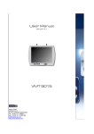
The diagram on page (6) summarizes the memory map described
so far and shows the suggested locations for the Video Display
Module and optional memory.
(5)
(6)
The separation of system space from user space results in
an upward progression of address values for user memory and a
downward progression for system memory. Future products have
assumed that this policy has been carried out and that the Video
Display Module (VDM), for instance, is located just below the
D000 start of system-RAM. This VDM should then start at
location CC00 hexadecimal. The presence of the VDM in the
C000-CFFF block means that no 4K board could be placed there.
It is, however, suited to a 2K PROM board and perhaps a 1K
memory board, should it become important to fill up this space
completely. The space from 9000 all the way to BFFF has been
marked as the best location for further extensions of the
System. As I/O drivers, loaders and other user software is
developed, it is suggested that they be placed in PROM in the
C000 to C7FF block. Future software packages will assume this
memory structure.
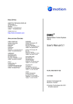
The program structure of the ALS-8 is most easily described
with the aid of the following diagram. The conceptual parts to
the program are shown as parts of a heirarchy not completely
unlike the structure of a government or business. In such a
diagram, it is assumed that the higher levels are able to
command the lower levels but not the other way around. In the
program sense then, the top most level can call on any of the
routines below as subordinates. It is assumed also in this
diagram that routines on the same level may call each other as
needed.
The top level, the executive level in this diagram,
represents the control center. It is this section which
controls the communications with the terminal, decides which
function is to be executed, and reports on errors to the user.
Each block on the function level corresponds to a command from
the ALS-8 command set. These routines, for efficiency's sake,
make heavy
(7)
use of the support routines on the next level, making the
overall package much smaller. These support routines have been
divided into two parts: general support, and I/O drivers. The
I/O drivers are support routines which handle the transfer of
data to or from external devices. They are logically distinct
from the general support routines because only the drivers
handle I/O and because the ALS-8 allows the user to define his
own routines as drivers, thereby adding to this part of the
system. Each new driver added usually has charge of a single
device. Only drivers can be used (as will be described in the
chapter on I/O drivers) to control high speed paper tape
readers, cassette recorders or printers. The custom commands
also add to the structure diagram but do so on the function
level. In addition, they can make use of all the general
support, I/O drivers, or other function level blocks to minimize
their own size and complexity. Other complete, self-contained
programs may be considered custom functions (like BASIC or
FOCAL) and this interaction with support routines or drivers is
only a convenience, not a requirement.
It is important to realize that many of the decisions made
by the ALS-8 in choosing support routines or drivers for a given
task depend on status information kept in the system RAM area.
Although there may be quite a number of I/O driver routines
identified to the system, only one input driver and one output
driver are considered current at any one time and their
identities are kept in this memory area. Similarly, certain
parameters will influence the flow of control through the
program structure.
(8)
CHAPTER III
TALKING TO THE ALS-8
The command set recognized by the ALS-8 can be naturally
divided into five categories; MEMORY, FILE, EDITING, I/O and
SYSTEM commands. The memory commands are used to enter data
into memory or examine the contents of a section of memory.
Usually these data transfers are between memory and the keyboard
and printer of the terminal but with proper equipment and
drivers, the memory commands become a means of saving and
restoring programs. The file commands verify, relocate, and
manage up to six files of information in memory while the edit
commands manipulate the contents of the files. The category of
system commands includes all the commands which define system
parameters, symbols, and drivers. It also contains commands
which execute the assembler, the optional simulator, or any user
designated location(s) in memory. The following table lists the
command names in their respective categories. The names marked
with an asterisk are commands used only by the optional VDM
Editor or Simulator software packages.
MEMORY
FILE
EDIT
SYSTEM
ENTR
DUMP
FILE
FILES
FCHK
FMOV
FIND (*)
DELT
EDIT (*)
LIST
TEXT
RNUM
IODR
SWCH
MODE
ASST
ASSM
EXEC
SIMU (*)
AUTO (*)
SYML
SYMLE
SYMLD
STAB
CUST
TERM
FORM
NFOR
The above list represents the default command set
recognized by the ALS-8 executive routine. Individual ALS-8
functions, while operating, will recognize other lines as
inputs. The ENTR command, for example, takes control of the
terminal and expects to receive numeric input data to place in
memory. This function must be given a special character
signifying the end of input before it will return control to the
ALS-8 executive. The ENTR function will not recognize entries
from the
(9)
executive's command set. An error message is output to the
terminal when an entry line is unrecognizable.
Other than custom commands which have been covered, the
ALS-8 executive does recognize a command line type not shown in
the command set list. Lines beginning with a number are assumed
to be line entries to a file of information stored in memory.
Files are a very powerful feature of the ALS-8 which will be
thoroughly covered in Chapter V. For the moment it suffices to
note that they contain text (usually program text for the
assembler) and that they normally sequence their contents by
line numbers. The text you are now reading, however, is an
example of a text file without line numbers using the optional
TXT-2 extension to the ALS-8.
A number of the executive commands accept "arguments" as
modifiers for the associated function. The ALS-8 executive
allows a maximum of two numeric values and one ASCII argument as
modifiers to a command. How the arguments are used if they are
used at a11, depends on the command chosen. In use, the
arguments are interpreted by the order in which they appear.
Commands using an ASCII argument will expect it to be the first
argument given. The ASCII argument, usually a name in one of
the many tables used by the ALS-8, also has the requirement that
it must be enclosed in slash marks(/). The following example
shows a number of commands as they might appear with arguments.
ASSM 2000
ASSM 2000
3000
FILE
/FNAME/ 100
DUMP 101 110
CUSTE /HACF/307
IODR
/TAPES/ DF00 DF80
Most of the ALS-8 functions contain logic to handle
instances where an argument has been omitted. In such instances
a default rule, peculiar to the command and argument in
question, will be applied. The "ASSM" command shown in the
example above can be used with one or two arguments. The
command starts the assembler which begins by checking for a pair
of arguments. It interprets the first argument as the origin
(ORG) address for the program being assembled. The second
argument specifies the starting address for the assembler's
binary output (machine instructions). If this second argument
is missing, the assembler will take the value given in the first
argument for both arguments. The assembler has no provision for
defaulting two arguments so it will signal an error if the ASSM
command is given with no arguments. Default rules for all
executive commands will be given in the detailed description of
these commands in the upcoming chapters.
(10)
Again it is mentioned that the user functions attached to custom
commands have full use of the argument handling support
routines; the treatment of default conditions is naturally up to
the programmer.
Finally, it must be noted that there are some minor rules
to be observed in the use of command inputs with arguments. The
ALS-8 executive needs to separate the characters belonging to
the command from those of the arguments. Similarly, it needs to
separate arguments from one another. The requirement is
therefore put on the user to place at least one blank after the
command word and at least one blank between a pair of numeric
arguments. The slash at the end of an ASCII name argument is
sufficient to separate the name from any following numbers.
Numeric arguments may follow an ASCII argument with no
separating blanks as long as the ASCII argument was terminated
with a slash mark.
Responses from the ALS-8 in general depend upon the command
chosen. For the standard ALS-8 command set, the user is always
assured of a response; if a response is not a normal duty for a
command, the ALS-8 executive will send the word "READY" to the
user's terminal after completing the command.
(11)
CHAPTER IV
MEMORY RELATED COMMANDS
The simplest commands in the ALS-8 repertoire are the
memory related commands, ENTR and DUMP. They provide a means of
changing and examining memory locations directly from the user's
terminal. The output printing format of the DUMP command has
been made compatible with input format requirements of the ENTR
command. This permits these commands to be used for saving
programs on a mass storage device and returning it to memory at
a later time. This feature will be covered here and in the
chapter on I/O drivers.
The ENTR command requires a single argument defining the
starting address for the data to be entered. The command starts
the corresponding ENTR function which assumes control of the
user's selected input device until receiving the character"/"
signifying the end of the input stream. The actual input to the
ENTR function is a list of values, each between 0 and 255
decimal in magnitude. These values must be listed in the order
they are to be placed in memory, and each must be separated from
adjacent values by at least one blank. The following shows
typical sequences using this command. Note that the input list
may use any number of lines up to the "/" mark.
ENTR
100
20 303
55 40
16 12
107 200 303
100 0
/
READY
ENTR
2001
101 200
/
READY
ENTR
3
0 7/
READY
The argument and input list can be in octal, as shown
above, or in hexadecimal depending on the current mode parameter
set by the system class command MODE. The MODE command affects
the operation of other ALS-8 commands, not just memory commands.
It takes a single decimal argument, 8 or 16, which is stored in
the system parameter defining the base for command inputs. If
any inputs are received which are impossible to decode with the
current base. a "WHAT?" will be sent to the user's terminal.
The ALS-8 initializes this parameter at start time to 16 and
this value is changed only with MODE. The following shows
possible errors associated with the MODE parameter:
MODE 16
ENTR 156000 (Octal address)
WHAT?
(12)
MODE 8
ENTR CC0D (Hex address)
WHAT?
MODE 16
ENTR BF2
52 49 EE 4F 52 F6 43 50
5 A0 0 84 E4
43 2 303 22
WHAT?
In the last of the examples, the values up to the error are
properly stored by the ENTR function. The corrected input will
have to restart at the place of the error.
An added feature of the ENTR command is that the present
storage address may be changed during input without having to
stop the process and restart with a new argument. The "present
storage address" always starts with the value given by the
attached argument to ENTR, and the first input value is put in
this location; inputs are placed in successive locations. The
user has an opportunity at the start of each input line to
redefine this current address. If the first value is followed
immediately by a colon(:), it is treated as a new address rather
than a memory value. While this seems only a minor convenience,
it becomes the key to making the output of DUMP compatible with
ENTR input. The following shows the first example of this
chapter rewritten using this feature.
MODE 8
ENTR 100
2 303 55 40 16 12 107 200
303 100 0
2001: 101 200
3: 0 3 /
READY
The DUMP command displays the contents of memory starting
at the address specified in the first argument and continuing to
the address specified by the second. As with ENTR, both the
arguments and the output follow the base parameter set by MODE.
The DUMP command can also be used with just a single argument;
in this case it types out only the location specified in the
first argument.
The lines output by the DUMP command each start with the
current address followed by a colon. The remainder of the line
contains the hexadecimal or octal contents of the memory
locations beginning with the printing address. In either the
octal or hexadecimal mode, the DUMP command puts sixteen values
on each line. Because this output is formulated properly for
ENTR, those users with a paper tape punch can save the output
directly on tape and reread it later with ENTR. In this case,
the standard ALS-8 I/O driver could be used. Saving programs on
other devices will require
(13)
using special drivers. The following shows a simple example of
DUMP in the hexadecimal mode.
DUMP 40 52
0040: OA D8 D6 07 C9 DB 00 E6 45 00 DC 01 D3 02 F8 CF
0050: E6 7F C9
(14)
CHAPTER V
FILES AND FILE COMMANDS
The ALS-8 relies very heavily on the use of files; for they
represent a very powerful way of managing data in text form. A
file is a sequence of information stored in user designated
memory. The information is broken into "lines" which are duplicates of the terminal input lines which define them. Each line,
both as it is input and as it is stored in memory, starts with a
line number defining its position in the file relative to other
lines. Lines with the lower line numbers are at the start or
"top", of the file while higher numbered lines have positions
farther "down" in the file. The lines do not have to be entered
in numeric order by the line numbers. The ALS-8 will reposition
other lines to make sure the proper order is kept internally.
Once in memory, files can be renumbered using the RNUM command.
Files are known to the ALS-8 by name and up to six files
can be defined and managed at any one time. File names may have
up to five characters. Rather than having each file-related
command specify which file is to be operated on, the ALS-8 has
the user define "Current File". Using the FILE command, the
user can specify which of his defined files is to be considered
"current". All file operations will apply to this file until
the Current File is redefined with the FILE command.
To create a file the user must give a name for the file and
a starting address for it. This is done by using the FILE
command with an ASCII argument for the FILE NAME and a numeric
argument as the START ADDRESS for that file. In this way, the
FILE command can be used to create a new file as well as make an
already existing file current. File names are kept in the
system RAM area in a table called the "File Name Table". These
names can also be removed from this list of defined files by
using the FILE command; a numeric argument of zero erases the
name from the table but does not affect the memory containing
that file. These file parameters may be restored later with the
FCHK command thereby allowing the user to actually have more
than six files of information in memory at one time. The ALS-8
does not, however, keep track of more than six. The following
shows three short files being created. Note that the FILE
command used with no arguments returns a message to the terminal
defining the Current File, its start and end addresses.
FILE/ONE/ 100
ONE 100 100
(RETURNED BY ALS-8)
1 This is the first line of file ONE.
26 THIS IS THE SECOND.
(15)
29 Line 3
FILE /TWO/ 200
TWO 200 200
FILE /THREE/ 6A1
THREE 6A1 6A1
10 Dear John,
12
Pay me or I won't be
14 your friend.
15
See you soon,
17
Igor
FILE /TWO/
TWO 200 200
1300 File Two gets this line
1984 UPPER CASE OK.
1000 lower case ok.
2710 End TWO
FILE
TWO 0200 02C0
This example points out a number of requirements and
features omitted in the discussion so far. Line numbers, for
instance, are normally followed by a blank but this is not
required by the editor functions. The example also illustrates
the fact that line numbers do not have to be absolutely
consecutive numbers. File line numbers are always decimal and
must lie in the range 0 to 9999.
A file, "TWO" in the example, can be entered into the File
Name Table and saved during the definition of :THREE" although
it is empty. Later it can be made the current file and
information can be entered into it.
Files naturally have a length as well as a start location
and the user must be careful that, in adding text to a file, he
does not accidentally write file information over a program or
another file. The ALS-8 assumes that the user knows where file
information and programs are located. To help the user manage
his files, the ALS-8 provides three file related commands: FILES
(different from FILE), FMOV, and FCHK.
The FILES command produces a listing of the files in the
File Name Table. This listing includes the start and end
addresses for the files so it is a simple matter for the user to
spot and avoid memory conflicts. Should a memory conflict
threaten, the current file can be moved to a different location
in memory with the FMOV command. FMOV requires only a single
argument defining the destination address for the Current File.
This argument may not be zero, but no other restrictions are
placed on it.
(16)
The last of the file related commands is FCHK which
verifies the internal structure of the Current File and updates
the file and address if necessary. If, for any reason, the file
is not properly formatted in memory, FCHK will send the message
"FILE ERR" to the terminal. This command can be very useful in
restoring files. Earlier it was mentioned that the contents of
a file were not affected by removing the file's name from the
list of defined files. Assuming that subsequent operations have
not altered the memory contents for that file's information,
FCHK can return it to an active, useful status. Similarly, the
contents of a previously saved file could be ENTR'ed into memory
and reactivated with FCHK. The following example shows some
typical uses of FCHK.
FILE /COPY/ 700
define a file name. Leave empty.
COPY 700 700
FILE /OLD/ 600
define file "OLD".
OLD 600 600
10 WAIT IN 377
15
CMP A
20
JZ WAIT
25
RET
40
END
FMOV 700
move OLD to start of COPY.
Store program in it.
OLD 700 736
FILES
OLD 700
736
COPY 700 700
FILE /OLD/ 0
FILES
delete OLD from list.
check defined files.
COPY 700
700
FILE /COPY/
only COPY. thought to be empty.
make it the current file.
COPY 700 700
FCHK
COPY 700 736
FILES
redefine end address.
NEW 600
COPY 700
FCHK
NEW 600
FILE
examine file starting at 600.
OLD is O K.
600
736
636
NEW 600 636
check Current File, "NEW".
contents recovered.
(17)
CHAPTER VI
EDIT COMMANDS
The ALS-8 contains a number of editing commands designed to
manipulate the contents of a file. All of these commands
operate on the Current File so the user is cautioned to check
the status, and perhaps identity, of the Current File before
using these functions. This, as described in the last chapter,
can be done with the FILE command. ALL the EDIT commands use
decimal line numbers as arguments where required. (NOTE: These
commands are separate from the optional VDM EDITOR package, TXT2, sold by Processor Technology.)
The EDIT command set contains two commands designed to
print the contents of the Current File: LIST and TEXT. The LIST
command outputs the Current File ordered by increasing line
number. It accepts up to two arguments defining the start and
stop line number for the printing. If only one argument is
given, the LIST function assumes that it is only to print the
single line identified by the first argument. When both
arguments are omitted, the entire file is printed. The
following example exercises these options. (Examples show
formatted output.)
FILE /SMPL/
1A2B
0 WAIT EI
0010JMP WAIT+1
0020 *
THIS SETS INTERRUPT AND WAITS
0024
END
LIST
0000
0
WAIT
EI
LIST
0000 WAIT
EI
0010 JMP
WAIT+1
0020 * THIS SETS INTERRUPT AND WAITS
0024
END
The TEXT command is very much like LIST; the only
difference is that its output omits the line numbers. This
feature is generally used for files containing regular text as
opposed to program code. This allows letters, notices, or
papers to be printed without line numbers. Since the user must
specify line numbers for arguments in edit commands, the TEXT
command obeys the argument conventions used for LIST.
(18)
The following shows the last example reprinted using TEXT.
TEXT
WAIT
*
EI
JMP WAIT+1
THIS SETS INTERRUPT AND WAITS
END
The ALS-8 system RAM has two parameters pertaining to LIST
and TEXT; the formatting flag and the terminal width parameter.
"Formatting" refers to the spacing or layout of the printed
results from the two functions. A formatting "flag" parameter
is a word in a system RAM which tells LIST or TEXT whether or
not they should rearrange the contents of each line in a form
especially suited to assembly language output. This parameter
is controlled by two system commands: FORM and NFOR, which
indicate "formatting" and "no formatting" respectively.
Naturally, a file not containing a program is more readable when
not formatted. The FORM and NFOR commands require no arguments,
and the parameter set by them remains in effect until explicitly
reset by the user.
The terminal width parameter, set by the command TERM,
contains an integer which represents the line width for the
current output device measured in characters. This parameter
has no influence on LIST or TEXT when the formatting feature is
suppressed. When formatting output for either output command,
the terminal width value determines the extent of formatting.
When it is fewer than 80, minimum formatting is performed. When
it is more than 80, the maximum formatting is performed.
Terminal width also controls the maximum length of input lines
as well as the acceptable line length during FCHK.
The DELT command allows the user to delete a line or group
of lines from the Current File. It accepts one or two arguments
identifying the first and last line numbers of the group to be
DELETED FROM THE FILE. When used with only one argument, DELT
assumes that it is only to delete the single line designated by
the first argument. The ALS-8 executive, however, rejects line
numbers input with no line. Thus, line 40 in the following can
be deleted with "DELT 40" or simply 40 followed by a carriage
return.
FORM
FILE
A
0280 02AF
(19)
LIST
36
0036
0039
0040
0044
DELT
DUP
LIST
36
0036
0039
0044
DUP
44
LXI H,0
DAD SP
SHLD HOLD
RET
40
44
LXI
DAD
RET
H,0
SP
The last command in the edit set is RNUM which renumbers a
file given a start line number and increment. When finished,
the Current File's line numbers will begin with this first
number, and all adjacent line numbers will differ by the value
of the second argument. If the second argument is omitted, the
RNUM function will use five as the increment. The largest value
allowed for this increment is twenty-five. The RNUM function
also will change the increment to one if the line numbers exceed
9000. The example below shows a small program being renumbered.
LIST
0025 INSTAT
IN
TTS
0030
ANI
DR
0035
JZ
INSTAT
RNUM 8000 10
TEST 1000 1030
LIST
8000
8010
8020
INSTAT
IN
ANI
JZ
TTS
DR
INSTAT
(20)
CHAPTER VII
I/O DRIVERS AND COMMANDS
The term "I/O Driver" refers to a routine used to transfer
textual data between the ALS-8 routines (or user routines) and
an associated input or output device. Its basic duties are to
interpret a request for data transfer from some calling routine
and to translate it into a sequence of reads or writes suited to
the conventions assumed by the electronics of the external
device. This relieves the calling routine of the responsibility
of handling separate conventions for many devices.
Conceptually, an ALS-8 routine can ask for data from any input
device in the same way or send data to any output device. It
must formulate the request and simply choose the routine to
handle the request and the device.
The ALS-8 has a table of driver routines in its system RAM
area and a parameter identifying the current pair of drivers
(input and output). When an ALS-8 function requires input or
output of a character, it uses this parameter to choose the
proper driver. The table for these routines contains a name and
pair of addresses for each entry. The IODR command handles
entries to and deletions from this table, as well as defining
the "current" driver and printing out the table's contents.
Used with a name argument of one to five characters and two
numeric arguments obeying the current value of MODE, the IODR
command will enter the name and addresses into the table. If
used with no arguments at all, IODR prints the contents of the
table. Since drivers are selected as pairs, special functions
can be implemented such as read from high speed paper tape both
with and without printout. Entries can be deleted by using IODR
with the entry name as an argument followed by a single zero
argument. The example shows IODR being used in these ways.
IODR /TAPES/
DF00
DF40
TAPES DF00 DF40
IODR /TVTWT/
DF80
DFC0
TVTWT DF80 DFC0
IODR
SYSIO E200
TAPES DF00
TVTWT DF80
E240
DF40
DFC0
(21)
IODR /TVTWT/
0
IODR
SYSIO E200
TAPES DF00
E240
DF40
SYSIO, shown in the above, is the default I/O driver which
handles the main terminal. It remains the current driver until
another from the list is explicitly defined by IODR in yet
another form: IODR with just a name argument. Making a driver
"current" assumes that the corresponding routines are loaded and
ready for use because the subsequent ALS-8 commands will have
switched to using those addresses for I/O. Assuming that
"TAPES" in these examples represents drivers for a cassette
recording unit, data could be loaded into memory with the
following:
IODR
ENTR
(the
not
/TAPES/
200
ENTR function will retrieve data from the cassette and
the terminal keyboard)
The discussion on drivers so far has covered only the basic
duties of drivers. Because the system only has to know where
the routine starts, the programmer has an enormous amount of
flexibility. The driver is a program capable of handling any
number of devices in a single call if desired. It has access to
system parameters and tables so it can check status words or
find file information. When used with functions like ENTR, the
driver can accept data in whatever form the device will provide
it and then reformat it so that the necessary address and colon
are appended to the start of each line. There is also no
restriction that more than one driver can't be assigned to a
single device. One line printer driver might simply echo the
data given to it on the page. Another driver in the list might
count lines so it can automatically skip the paper folds and
print headings at page tops. Similarly, a set of drivers could
exist for communication with the VDM as within the TXT-2
extension package.
These capabilities are futher enhanced by the fact that any
user program has access to the driver list. It can, if desired,
ignore the "current" driver pair, search the table for a
specific name, retrieve the corresponding addresses and begin
using those routines. To write such a program, the user must
know the addresses of the table, the parameter identifying the
current driver, and the ALS-8 routines which search tables. The
conventions for the routines and memory storage must also be
learned, but the enormous flexibility compensates for the
trouble.
(22)
CHAPTER VIII
SYSTEM COMMANDS
The commands described in this chapter cover a wide range
of functions. ASSM, ASSI, and their derivatives assemble a
program and load the resultant machine instructions into a
designated section of memory. CUST and its derivatives, CUSTE
and CUSTD, manipulate the Custom Command Table stored in system
RAM. SYML, SYMLE and SYMLD are like the CUST set except that
they manage the System Symbol Table in the system RAM. Other
commands in this group define I/O drivers, set system
parameters, and execute routines starting at user defined
addresses.
All of the commands related to the ALS-8 resident assembler
accept one or two arguments. The first argument defines the
origin for the program, while the second, if given, specifies
the start address for the machine language output of the
assembler. If only one argument is given, the assembler uses it
for both the program origin and the start address for the binary
form of the program. The binary machine language output by the
assembler is known as "object code". It is the only form
executable by the 8080 CPU. The program text by contrast is not
executable but much more readable for humans. It is called
"source code".
The set of assembler-related commands ASSM, ASSME, ASSMX,
ASSMS, ASSI, ASSIX and ASSIS all produce assembled object code
programs for the program source code. Each has, however, its
own option associated with it. The fourth, and where applicable
the fifth, character in these command names is used to select
the options to be used on a particular assembly run. The fourth
character, "M" or "I", divides the group into two sets of four
commands. These sets differ in the source they use for program
text. The "M" group uses the Current File as its source whereas
the "I" group reads the source program through the CURRENT INPUT
DRIVER. The fifth character of the assembly command names
control options for the assembler output listing. If omitted,
as in ASSM or ASSI, the listing is a
one-output-line-per-source-line printout identifying errors,
addresses, and machine language values produced from the
program's instructions. An "E" suffix suppresses all printout
except for those lines containing errors. "S" and "X" suffixes
list the contents of the symbol table immediately following the
program source listing. The "X" option adds cross reference
information between program symbol names and the line numbers
that they occurred in. Formatting of the assembler output
listing depends on the parameter defining the terminal width and
the "FORM" switch.
(23)
The CUST command prints out the current contents in the
Custom Command Table. The custom names must be four or five
characters and are considered unique to only four characters.
When a custom name is given to the ALS-8 as a command, this
address is retrieved from the table and the ALS-8 passes control
to this address (as a subroutine call). Entries to this table
are made with the CUSTE command which requires an ASCII argument
to be used as the new name and an address to be called for the
command. The address argument follows the base set by the last
MODE command. CUSTD deletes custom names from the table. It
requires only the single name argument. Users are cautioned
that the twenty-two custom name limit is their responsibility to
watch as the ALS-8 does not warn when the number of entries
exceeds the table's boundary.
Custom commands can be attached to any kind of program.
The FOCAL and BASIC software packages both load starting at
address zero, so they cannot be in the machine at the same time.
Either could be loaded, though, and its name entered as a custom
command. Both software packages come with a short program which
must be ENTR'ed first; this program loads INTEL format paper
tapes. This loader is then started and the paper tape data is
stored in memory. The following outlines such a sequence.
MODE 16
ENTR 1800
(type in hexadecimal for INTEL paper tape loader)
/
CUSTE /LOAD/ 1800
LOAD
(start paper tape-when done reading restart ALS-8 at
E060)
READY
CUSTE /FOCAL/ 0
CUST
LOAD 1800
FOCAL 0
FOCAL
* (this is the ready asterisk from FOCAL)
The System Symbol Table is managed with the SYML, SYMLE,
and SYMLD commands. SYML, like CUST, only prints out the
contents of the table. SYMLE and SYMLD enter and delete names
and their associated values from the symbol table. SYMLE
requires a name argument of five letters or less and a numeric
argument representing the symbol's value. SYMLD handles the
deletion of symbol names from the table and, like CUST, requires
only the name argument. Unlike the custom table, the System
Symbol Table is not restricted much by a maximum length. Its
physical
(24)
location allows it just over 3K of memory and it is all but
inconceivable that this could be overrun. The user can
effectively set a maximum length of his own by setting up other
tables or drivers in this 3K expanse. The example here shows
two important symbol names being entered into the System Symbol
Table.
SYMLE /SP/ 6
SYMLE /PSW/ 6
SYML
SP
6 PSW 6
D30E (End of Table address printed following listing)
The symbols shown in the example above are needed by the
resident assembler for programs which access the 8080 Stack
Pointer, "SP", or the Program Status Word, "PSW". The resident
assembler can only recognize single letter register names like
B, C, D, E, H, L, and A. The user can define the SP and PSW
symbols in each program he writes or enter them once in the
System Symbol Table for all the assemblies he performs. The
assembler produces a table for the symbols it finds in a program
and this table, inaccessible to the user, is called the Assembly
Symbol Table. It is created from scratch for each assembly. If
the program instructions make reference to a symbol which has
been given no value in the program itself, the assembler will
try to fetch the value from the system's table. It is a great
convenience then to be able to define symbols once in this
System Symbol Table rather than each time in a program. This
makes programs both shorter and more versatile, since single
changes in the symbol table values can affect the origins,
parameters, or subroutine connections for a number of programs.
The ALS-8 allows the user the freedom of specifying where
the Assembly Symbol Table should start in memory. The STAB
command defines this location from an argument which obeys the
current MODE value. This start location must be defined before
the first assembly is made and it is suggested that this table
be placed at D700 hexadecimal. This puts it well into the
system RAM area leaving over 1K for the System Symbol Table. It
also leaves over 2K for the assembly Symbol Table which is
sufficient for all but the largest programs. This assumes
naturally that the area between D700 and E000 is not full of I/O
driver routines (see Chapter II). The following might be used
to start an assembly.
STAB D700
ASSM 1A0
(25)
The loaded output of the assembler, the object code, can be
executed without having to make an entry in the Custom Command
Table. The EXEC command generates a subroutine call to the
address specified by its argument. When finished, the program
at this location only has to generate a return with the 8080 RET
assembly instruction and control will return to the ALS-8
executive. The argument to the EXEC command naturally follows
the number type specified by the MODE parameter. In an earlier
example, the name "FOCAL" was entered into the Custom Command
Table with an associated address of zero. When "FOCAL" was
given as a command the address 0 was given control by the ALS-8.
This could also have been done by giving the command "EXEC 0".
In the event that a program does not automatically return
to the ALS-8, it will be necessary to stop the machine from the
front panel, set the address switches to E060 and hit the RESET,
EXAMINE, RUN switches. FOCAL, BASIC, and INTEL LOADER are
examples of programs which normally do not have an ALS-8 return.
If a user program goes awry the same procedures can be used to
restart the ALS-8. The user may want to check his files and
data to ascertain whether or not they have been damaged by the
errant program.
(26)
CHAPTER IX
COMMAND SUMMARY
This chapter contains a summary of the ALS-8 commands in
the order they were presented. The reader is advised to consult
earlier chapters for any details omitted here. Following
chapters will cover the ALS-8 assembly language instruction set.
The descriptions given here use the convention of enclosing an
argument in parentheses when it is optional. Arguments will be
signified by lower case names suggestive of their use; "addr1"
for instance, will be an argument representing an address.
ENTR addr
This command reads numeric data from the current input
driver and stores it in consecutive memory locations starting
with the address specified by the argument. The data may
continue for any number of lines; the function will return
control to the ALS-8 executive only when it encounters a slash
(/). At the beginning of every line, the current address
pointer can be changed by specifying a new value followed by a
colon (:). Both the data and addresses are interpreted in octal
or hexadecimal according to the currently defined MODE. The
length of any input line is limited by the current value of
terminal width.
DUMP addr1 (addr2)
This command displays the contents of memory from "addr1"
to address "addr2". If only one argument is given, only the
contents of address "addr1" are displayed. The arguments and
printed results obey the number base set by MODE.
MODE base
The argument "base" for this command sets an ALS-8
parameter which is used in converting binary data to readable
form. The argument is decimal and must be either 8 for octal or
16 for hexadecimal. All ALS-8 arguments representing memory
data or addresses will be affected by this command. Arguments
which specify setting terminal width or line number will always
be decimal. Initially the ALS-8 assumes a mode of 16.
(27)
FILE COMMANDS
The FILE command has many different forms each with its own
distinct function. The following describes each particular
form. All name arguments ray be one to five characters long.
FILE
This form will print the name of the current file, its
start address and end address.
FILE /fname/
This will search through the current list of file names for
"fname". When found, this file will be marked as the current
file and all subsequent file operations will be made on it. If
not found, the error message "WHAT" is sent to the terminal.
FILE /fname/ addr
This enters a file name, "fname", into the list of names
kept it the file table. The argument sits both the start and
stop addresses associated with the name. If the file already
exists in the table an error message FCON is output to the SYSIO
output device. The file "fname" always becomes the Current
File. Addresss "addr" must not he zero.
FILE /fname/ 0
File "fname" is removed from the file table and forgotten.
There will be no Current File when this command is finished.
FILES
The FILES command uses no arguments. It lists the names,
start and end addresses for all the files known by the ALS-8.
This command does not affect the status of the Current File.
FCHK
This command checks the structure of the Current File.
begins at the start address contained in the file table and
(28)
It
continues until it finds an end of file mark (01 hexadecimal) or
an error. An error is signaled with the message "FILE ERR."
followed by the address of the error. The location of the end
of file mark becomes the end address of the Current File. Using
FCHK, files may be input directly into memory from magnetic tape
or disc and recreated.
FMOV addr
The Current File is moved by this function to memory
locations starting at "addr". The start and end address values
associated with the file are also changed. The copy remains the
Current File and an FCHK is automatically performed. If the
file was inadvertently moved to a location without memory, a new
file can be created at the old address and the contents
recovered using the FCHK command.
While there is no restriction prohibiting a file from being
moved to an address contained by the original, the user should
note that only the copy will have a valid structure after such a
move.
Text can be input to a file by simply specifying the line
number and contents for that line. The line number is an
integer from 0 to 9999 and it normally is followed by one blank.
If the file contains a line with this same number, the new data
is entered in place of the old. The contents of any file can be
interpreted as text or as assembly language source. Lines
intended for the assembler are composed of distinct fields which
are separated by groups of blanks. These fields can be
repositioned during printout by an automatic formatting feature
controlled by the TERM, FORM, and NFOR commands. The TERMINAL
WIDTH parameter also controls the maximum length of lines input
to the file.
TERM width
The ALS-8 parameter representing terminal width is
initially set to 80. The user can, however, reset this at any
time with the TERM command. The decimal argument "width"
contains the size of the terminal line. This influences not
only output formatting, but also input line length for files
(FCHK). The maximum value for TERM is 119.
FORM
This command sets a parameter in the system RAM for the
ALS-8 which specifies whether or not printed listings of
assembler source or files are to be formatted.
(29)
NFOR
This deactivates the formatting feature described above.
The ALS-8 is initialized to the non-formatted state.
LIST line1 (line2)
This is used to print out contents of a file between the
specified line numbers. When only one argument is used, the
single line identified by line1 is printed. Line numbers and
line number arguments are always decimal numbers. This command
prints the contents of each line following the corresponding
line number. (When using the optional VDM EDITOR, the LIST
command will list files entered without line numbers.)
TEXT line1 (line2)
Like LIST, this command prints file contents from line1 to
"line2". It does not, however, print out the line numbers at
the start of each line. This is a useful feature for letter
copy. Both TEXT and LIST contain the formatting routine which
is controlled by FORM, NFOR, and TERM.
DELT line1 (line2)
DELT removes a line or series of lines from the Current
file starting at line number line1 and continuing through
"line2". In its single argument form, only the line specified
by "line1" is deleted; it is usually easier to delete single
lines, however, by typing the line number followed by just a
carriage return.
RNUM line# (increment)
RNUM renumbers the Current File so that its first line
number will be "line:" and each successive line number will be
greater than the last by the quantity defined in "increment".
If "increment" is omitted, RNUM will use a default increment of
five. The largest allowable value for the increment is twentyfive and, regardless of increment value at the outset, RNUM will
use an increment of one after the line numbers reach 9000. RNUM
ends by calling FCHK, thereby checking the file after
renumbering.
ASSEMBLER COMMANDS
The ALS-8 resident assembler is activated with different
options from the eight commands summarized below. Each requires
(30)
an origin which is used as the address from which the routine
must eventually be run. The second argument to each of these
commands is the start address for the storage of the assembled
program. A program "origin" and "load point" must agree if it
is to be run rather than temporarily stored. The variations in
the commands mainly affect listing length and input source.
ASSM origin (load address)
This form assembles from source contained on the Current
File. If the "load address" argument is omitted, the assembler
will load at the address given by "origin". A full listing of
the assembly and errors is written to the current output driver.
ASSME origin (load address)
This is the same as ASSM except that only lines containing
errors are listed.
ASSMS origin (load address)
This form produces a full listing and adds a listing of the
assembler's symbol table to the end. The current values,
usually addresses, of the symbols are also given.
ASSMX origin (load address)
This is a further expansion of ASSMS in that the symbol
table listing provided at the end is cross referenced to file
line numbers. The summary for each symbol then contains its
name, value, and a list of locations which used it.
The four remaining assembler commands ASSI, ASSIE, ASSIS,
ASSIX are similar to the four commands just listed except for
the source of the assembly language code. These four use the
I/O driver selected by IODR for reading the program source. A
special driver is required for this use and the user is referred
to the ALS-8 Specification sheet outlining the requirements of
this driver.
ASSI
ASSIE
ASSIS
ASSIX
origin
origin
origin
origin
(load
(load
(load
(load
address)
address)
address)
address)
(31)
assemble with full listing.
assemble. list only errors.
assemble. list with symbol table.
assemble. list with cross
reference table.
STAB address
This command sets the starting location for the Assembler
Symbol Table. This address is not initialized to a usable value
so this command must be called before any assemblies are
attempted.
CUST
This will print out the contents of the Custom Command
Table. Each output line will contain name and address pairs.
The addresses are printed according to the base by MODE and the
end address of the table is printed following the list of names.
CUSTE /cname/ address
This will enter the name, "cname", into the Custom Command
Table with its associated address value. If this name already
exists in the table, it is merely given a new associated value.
The name may be four or five characters long, but it is only
unique to four. Thus "HEART" is the same custom name as "HEAR".
A maximum of twenty-two such names is permitted each requiring
eight bytes of table space. The table must not go beyond D300
or interference with the System Symbol Table will result.
CUSTD /cname/
This deletes the specified name from the Custom Command
Table.
EXEC addr
The EXEC command performs a subroutine call to the address
specified by "addr". The argument, being an address, obeys the
number convention set by MODE.
SYML
This command lists the contents of the System Symbol Table.
The values listed in the name/value pair are assumed to be
addresses and, as such, will follow the current MODE for type.
The names can be one to five characters in length. The end
address of the table is printed following the list of names and
values.
(32)
SYMLE /sname/ addr
SYMLE is used to enter a name and its corresponding value
into the System Symbol Table.
SYMLD /sname/
This will delete the symbol, "sname", from the System
Symbol Table.
I/O DRIVER COMMANDS
There are only two names in the I/O driver command set but
one, IODR, has many forms. The following summarizes its
functions and describes the other command, SWCH.
IODR /dname/ in out
This form of IODR enters the name "dname" into the I/O
driver table with the two addresses, "in" and "out". When this
driver pair becomes active, the ALS-8 functions will try to read
text data through a routine located at the address "in".
Similarly, output from these functions will be sent to the
routine assumed to be at address "out". This form of the
command does not activate this driver pair, only defines it. If
address "in" is zero, followed by a proper output address, the
current SYSIO input driver will be assigned as the input driver.
Also, if the output driver address is zero, the current SYSIO
output driver will be assigned. If the output address is
omitted, after being preceded by a valid input address, a
special output address will be assigned to allow no output.
(BIT BUCKET)
IODR
Used without arguments, this command prints out the
contents of the I/O driver table. Each line of the printed
summary contains the name, the input driver address, and the
output driver address.
IODR /dname/
This informs the ALS-8 that the default system driver,
SYSIO, is to be used for one more command line. The driver
pair, "dname", is then used until an ALS-8 command returns
control to the executive. This one command delay enables the
(33)
user to choose an ALS-8 function from his terminal before
switching control to the new drivers. SYSIO, the terminal
driver pair, is automatically reactivated at the conclusion of
the ALS-8 function or under error conditions.
SWCH
When used after the above form of IODR, the new drivers are
activated for use by the ALS-8 executive, not an ALS-8 function.
The executive then will read a command and any associated data
with these drivers before returning to SYSIO.
(34)
CHAPTER X
THE ALS-8 ASSEMBLER
The resident assembler is perhaps the strongest feature of
the ALS-8. It is a program designed to convert the text for a
program into the binary machine code form of a program. The
textual representation, called "source code", is very readable
by humans but only binary form is executable by the computer
hardware. In typical use, the source program is written onto a
file and edited. This is then assembled with one of the ASSM
commands and the resultant binary, or "object code", is stored
in memory. There it can be used as a driver, a custom command,
or a program to be run by the EXEC command.
A source program written in assembly language is
interpreted by the assembler on a line-by-line basis. Since
files are also line structured, they become a natural storage
area for program source. (The ASSI command series insures that
ALS-8 files are not the only storage medium for programs.)
Each line of the program must conform to certain rules in
order to be assembled correctly. An asterisk at the start of a
line identifies the line as being a comment and its contents are
not subject to the rules of the assembly language. Lines
without an asterisk are "statements" and these can be divided
into as many as four separate parts called "fields". Each field
has an entirely different function to the assembler. The first,
the "label field", gives a symbolic name to that line which can
be referenced by any statement in the program. The label must
start with an alphabetic character in column 1 of the line
(after any file line numbers). It may be any number of
continuous characters, though the assembler will ignore all
characters beyond the fifth. This means that the label names
"bridge", "bridg", and "bridget" will all represent the same
label. All fields are separated from one another by one or more
blanks.
STATEMENTS may contain either symbolic 8080 machine
instructions or pseudo-ops. The four fields of each statement,
NAME,OPERATION, OPERAND and COMMENT are scanned left to right by
the assembler. The assembler requires at least one blank
NAME
OPERATION
OPERAND
COMMENT
between each field for identification. For automatic formatting
however, the comment field must be preceded by at least TWO
BLANKS. Instructions which use only the operation field as does
(35)
RZ should be followed by a "dummy" operand if comments are to be
used with the statement. (Blanks in the following example are
shown as dashes ["-"] for clarity.)
RZ-.--COMMENTS ADDED AFTER TWO SPACES
CONSTANTS
*********
The ALS-8 Assembler allows the use of constants within the
operand field. Hexadecimal and decimal, as well as octal
constants may be used. When using either octal or hexadecimal,
the value should be followed by a "Q" or "H" to indicate OCTAL
and HEX respectively. When a value does not include a following
identifier, it defaults to DECIMAL but a "D" may be used for
clarity when desired.
MVI A,128
Move 128 decimal to register A.
LXI H,2FH
Move 2F hexadecimal to registers H&L.
MVI B,40Q
Move 40 octal to register B.
JMP
0FFH
Jump to address FF hexadecimal.
As shown by the last example, all constants must begin with
a numeric quantity. When hexadecimal values begin with the
letters A-F, they should be preceded by the numeric value zero.
EXPRESSIONS
***********
An expression is a sequence of one or more SYMBOLS,
CONSTANTS or other expressions separated by arithmetic
operators. The ALS-8 Assembler allows the use of four primary
operators: ADDITION (+), SUBTRACTION (-), MULTIPLICATION (*) and
DIVISION (/). Expressions are scanned left to right with no
precedence given to any operator. Calculations are made using
16 bit arithmetic (module 65536) and overflow of values is
allowed. Single byte values for immediate instructions (as with
MVI A) must evaluate to a value between -256 to +255 or an
assembler error will result.
MVI
LDA
LXI
A,255D/10H
POTTS/256*OFSET
SP,30*2+STACK
There are two other special operators which may be used to
reference either the right (>) or the left (<) byte of a 16 bit
value. For example:
<1234H evaluates to 12H
>1234H evaluates to 34H.
(36)
ASSEMBLER ERROR INDICATIONS
***************************
The following error flags are output by the assembler when
the error occurs. As determined by the type of error, some of
the flags are output during pass one to indicate an invalid
assembly.
O -- OPCODE ERROR
L -- LABEL ERROR
D -- DUPLICATE LABEL
M -- MISSING LABEL
V -- VALUE ERROR
U -- UNDEFINED SYMBOL
S -- SYNTAX ERROR
R -- REGISTER ERROR
A -- ARGUMENT ERROR
The symbol found in the
operation field was not
recognized as a valid 8080
instruction or pseudo operation
of the assembler.
The symbol found in the name
field contains improper
characters.
Two labels with the same name
within the assembly.
Instruction requiring a label
doesn't have symbol in name
field.
Expression in operand field is
outside range required.
Name given for operand cannot
be found in symbol tables.
Syntax of statement does not
follow the requirements of the
assembler.
False name given to register.
Argument for operand improper.
Since the label field is optional, the assembler must have
a convention for identifying the second type of field, the
operation field, when the label is missing. The operation field
must, for this reason, be preceded by at least two blanks when
it starts a line. The contents of this field will be a two,
three, or four letter mnemonic chosen from the assembly language
set. This mnemonic defines the general instruction to be
assembled and it uses, where necessary, the third field, the
"operand", to modify or complete the instruction. An "ADD" in
(37)
the operation field tells the assembler that one of the 8080
registers is to be added to the 8080 accumulator.
The fourth possible field is the comment field which, as
its name implies, is reserved for comments. The assembler,
then, disregards anything after the third field. In statements
which have no operand field, it is a good idea to precede the
comment with a period followed by two blanks. Since no operand
is required, the period has no affect and the listing will be
properly formatted. Most of the examples in this chapter are
listed as though they were formatted and printed by the TEXT
command. The example below shows how a sample program file
might actually be input and exist in memory. Blanks are written
as "-" to show their significance; file line numbers are also
shown.
3-*-THIS-SUBROUTINE-SHIFTS-(H,L)-CIRCULAR-LEFT
5-LUP-XRA-A--CLEAR-THE-CARRY
8--CMP-B--SEE-IF-SHIFT-COUNT-DOWN
13--RZ-.--RETURN-TO-CALLING-ROUTINE
14--DCR-B--DECREMENT-COUNT
16--MVI-A,80H--TEST-MSB-OF-HL
22--ANA-H--COMMENTS-OPTIONAL
24--DAD-H--SHIFT-LEFT
26--JZ-LUP--IF-MSB-WAS-ZERO
29--INX-H--CIRCULAR-BIT-IN
35--JMP-LUP
40--END
The above illustrates the fact that "column 1" of each
program statement line must be separated from the file line by
at least one blank. When printed with the TEXT function the
above becomes:
* THIS SUBROUTINE SHIFTS (H,L) CIRCULAR LEFT
LUP
XRA
A
CLEAR THE CARRY
CMP
B
SEE IF SHIFT COUNT DONE
RZ
.
RETURN TO CALLING ROUTINE
DCR
B
DECREMENT COUNT
MVI
A,80H
TEST MSB OF H,L
ANA
H
COMMENTS OPTIONAL
DAD
H
SHIFT LEFT
JZ
LUP
IF MSB WAS ZERO
INX
H
CIRCULAR BIT IN
JMP
LUP
END
(38)
Instructions in the assembly language manipulate seven
8-bit registers, a 16-bit program counter called "PC", memory,
I/O devices, and a 16-bit stack pointer "SF". Both the
assembler and the hardware use a number convention for
identifying these registers. The numbers 0,1,2,3,4,5, and 7
each represent one of the 8-bit registers. Depending on the
instruction, a 6 can represent memory, the stack pointer, or a
special program status word, "PSW". Many of the instructions
assume a destination register for the results they generate and
many will also make assumptions on one of their input operands.
Addition, for example, is handled by the ADD instruction in the
assembly language and it assumes that the contents of register
7, called the accumulator, will be added to an eight bit
quantity from memory (6) or the registers (1 through 5). Its
result always goes to register 7. The operand for this register
is a number specifying which 8-bit value is to be added to
register 7. This operand appears in the operand field for the
instruction as shown.
LABL
XAD
ADD
ADD
ADD
ADD
7
0
3
6
DOUBLE
ADD IN
ADD IN
ADD IN
THE ACCUMULATOR
REGISTER 0
REGISTER 3
VALVE FROM MEMORY
The assembler uses a pair of tables, the Assembler Symbol
Table and the System Symbol Table, to find number values
associated with a symbol name. Label names from the label field
are stored into the Assembler Symbol Table along with the
addresses they represent in the object code. Assembling the
short example above would have added the names "LABL" amd "XAD"
to this table. The assembler always has eight entries in this
table, B,C,D,E,H,L,M, and A, for which it has the values 0
through 7. These are the names given to the registers and the
assembler will replace one of these names found in an
instruction with the appropriate register number. The last
example could be rewritten:
LABL
XAD
ADD
ADD
ADD
ADD
A
B
E
M
DOUBLE
ADD IN
ADD IN
ADD IN
THE ACCUMULATOR.
REGISTER B
REGISTER E
VALUE FROM MEMORY
A number of the 8080 operations use pairs of registers for
16-bit operands and for these operations, register B is paired
with C, D with E, H with L, and the program status word PSW is
(39)
paired with A. B, D, H, and PSW are the high order bytes in
these values. The instruction DAD, for instance, performs a
"double add" between the (H,L) pair and the (B,C) or (D,E) pair.
The result is stored again it (H,L). For these instructions,
the pair is designated the name of the most significant byte so
the possible PAD instructions are:
DAD
DAD
DAD
DAD
DAD
B
D
H
H
SP
which are equivalent to:
DAD
DAD
DAD
DAD
0
2
4
6
Note that 6, which could represent memory, SP, or PSW, is
taken by the DAD instruction hardware to mean the stack pointer.
"DAD M" or "DAD PSW" are equivalent to "DAD 6" and will then be
treated by the hardware as "add SP to (H,L)". Note also the
default list of register names does not include PSW or SP.
These may be entered into either the System Symbol Table with
the SYMLE executive command or into the Assembler Symbol Table
with the EQU assembler instruction (to be described). The
assembler will first try to fetch a value for a symbol from its
own table and, failing, will then try the System Symbol Table.
A number of the 8080 instructions are "conditionals"
meaning that the full operation is performed only if a condition
is met. The program status word, PSW, uses five of its eight
bits to represent the testable conditions. These bits are
called Sign, Zero, Aux, Parity, and Carry, and they reflect the
state of the accumulator after certain instructions. The more
significant bit of the accumulator is copied to Sign by certain
instructions. Similarly, certain instructions will set the Zero
bit (to 1) when the accumulator contains a zero value and it is
reset (to 0) when A is non-zero. Parity is set to 1 when A
contains an odd number of binary 1's and is reset when even.
The Carry bit's function is most easily described with the
conceptual aid of a ninth bit on the accumulator. Some
instructions will put the opposite (0 for 1; 1 for 0) of the
carry value into Carry; others will copy carry into Carry. The
reader is again reminded that some instructions do not
(40)
affect the values in PSW regardless of the contents of A. The
actions taken by each instruction concerning the PSW condition
bits will be given with the description of each instruction.
In the upcoming instruction summary, two types of assembler
instructions will be described: executable instructions and
"pseudo-ops". The executable instructions are those assembly
statements which must be converted into binary object form for
eventual execution by the CPU. Pseudo-ops, or pseudo–
operations, have the appearance of other program statements but
do not produce object code for the CPU. Instead they are used
to pass information to the assembler program itself. "ORG" for
instance, is used with its operand to define the "current
address counter" for that position in the program being
assembled. "END", another pseudo-op, signals the end of the
assembly language source code; the assembler will not try to
read or interpret lines beyond the line containing "END".
ASSEMBLY LANGUAGE INSTRUCTIONS
****************************
This section describes the assembly language instructions
and their function ordered by increasing complexity. An
alphabetically ordered summary will be given later with the
object codes generated for each instruction. In the following
description, optional fields will be enclosed in parentheses and
operands for the instructions will be represented by a short
lower case mnemonic. The operand "reg represents any constant,
symbol, or expression wits a value from zero to seven. This
value is used to select one of the seven registers or memory: B,
C, D, E, H, L, M, A. Operand "addr" can be an expression,
constant, or symbol which gives a value to be used as a 16-bit
argument, usually an address. A numeric argument is represented
by "const 8" and "const" values supplied for "const 8" must be 8
bits or less in magnitude.
The following three instructions provide the most direct
means of transferring 8-bit data from register to register,
memory to register, or register to memory. There is no single
instruction to transfer from one memory location directly to
another.
(label)
LDA
addr - LOAD Accumulator
(41)
This instruction fetches a byte from the memory location
specified by "addr". This value is then stored in A. PSW is
not affected.
(label)
MOV
dreg, sreg
-
move register to register
This instruction moves the contents of the source register,
"sreg", to the destination register "dreg". B, C, D, E, H, L,
M, and A (0 through 7) are legal values for "sreg" and "dreg"
except that both may not specify memory (M). When either "sreg"
or "dreg" specify memory, the CPU uses the contents of the (H,L)
register pair as the address of the memory byte to fetch or
store. The contents of the source register are not affected.
PSW is also not affected by the instruction.
MOVER
MOV
M,E
MOV
MOV
E,B
C,M
(label) STA
move contents of E into memory
location specified by (H,L).
copy B into E
load C from memory
addr STORE accumulator
STA transfers the contents of the accumulator to the memory
location specified by "addr". PSW is unaffected.
Arithmetic, logical, and comparison operations are handled
by eight instructions. Each of these operations is assumed to
take place between the accumulator and a register (or memory
location) specified in the operand field. All, except CMP,
produce an 8-bit result which is placed in the accumulator. The
program status word bits in PSW are all affected by any of these
instructions.
(label)
ADD
reg
-
ADD register to accumulator
The value in register "reg" is added to the accumulator and
PSW is updated. PSW "Carry" is set to 1 if the arithmetic
produces an overflow from the most significant bit (MSB).
(label)
SUB
reg
-
Subtract register from A
This instruction subtracts the value specified by "reg" and
places the result in A. The PSW carry bit is set to 1 if a
borrow was necessary during the subtraction; the actual ninth
bit carry, discussed earlier, would actually be zero in a borrow
situation. This is an example of carry being inverted for
storage in Carry.
(42)
(label)
ADC
reg
-
Add the specified register and Carry
to the Accumulator
The specified register and the current contents of Carry
are added to A and the result is placed in A. This is used
primarily in "multiple precision" additions in which a number is
actually contained in several (usually adjacent) memory
locations. Such an addition starts at the low order end of the
two numbers with the Carry bit reset to zero. Successive
additions with ADC on more significant bytes in the numbers are
corrected for overflow from the last (less significant)
addition.
(label)
SBB
reg
-
Subtract with borrow from A
This is the multiple precision form
the Carry (borrow) from A as well as the
is actually done by adding the Carry bit
before the subtraction is made. The PSW
after the subtraction.
(label)
ANA
reg
-
of SUB. It subtracts
value in "reg". This
to the value in "reg"
status bits are updated
logically AND reg and A
This function performs a "logical and" ( a Boolean
multiplication) on the contents of "reg" and the accumulator.
Conceptually this operation is performed independently on each
bit position of the two operands (A and "reg"). The
corresponding bit position in the result is set to 1, if, and
only if, both of the operand bits are 1's. 00110011 and
01010101 will leave the value 00010001 in A. The Carry bit is
always reset; other status bits are set or reset according to
the result.
(label)
ORA
reg
-
logically OR reg and A
This instruction performs a bit-wise "logical or" (Boolean
add) on the accumulator and the specified register. Each bit of
the result is set to 1 if either of the corresponding operand
bits is 1. 00110011 OR 01010101 will produce 01110111 for a
result. The Carry bit is always reset to zero. Other status
bits are set as dictated by the properties of the result.
(label)
XRA
reg
-
logical EXCLUSIVE OR reg and A
XRA is a bit-wise logical "exclusive-OR" function for the
(43)
OPERANDS, A and "reg". Each bit of the result will be 1 if one
(and only one) of the corresponding operand bits is 1. The
operand values 00110011 and 01010101 produce an "exclusive-OR"
result in the accumulator of 01100110. PSW status bits are
handled as in ANA, ORA. This function is often used to clear
the accumulator and Carry with an "XRA A".
(label)
CMP
reg
-
Compare A to Reg
This instruction performs an 8 bit unsigned compare of the
values in A and "Reg". The following status results:
(A) < (Reg)
(A) = (Reg)
(A) > (Reg)
Carry is set, zero is reset
Carry is reset, zero is set
Carry is reset, zero is reset
A compare is actually done by internally subtracting "Reg" from
A but storing the result.
There are eight instructions much like the register
operations described above, and they are called the Immediate
Instructions. They differ from register operations in that a
register (or memory) value is not used as an operand. Instead,
the operands are the accumulator as before, and an eight bit
value which is given in the operand field of the instruction.
This operand value may be the result of an expression, the value
of a symbol, of a constant, as long as the magnitude of the
value does not exceed eight bits. As with register operations,
all PSW bits are affected by these instructions.
(label)
ADI
const8
-
add value of const8 to A
The 8-bit value of "const8" is added to the accumulator.
As in ADD, its register operation counterpart, all PSW bits are
affected.
(label)
SUI
const8
-
subtract immediate from A
The immediate value is subtracted from A.
including Carry, follow conventions of SUB.
(label)
ACI
const8
-
PSW bits,
add value and Carry to A
"Const8" and the Carry bit are added to A.
affected.
(44)
PSW is
(label)
SBI
const8
-
subtract immediate with borrow
This instruction subtracts Carry bit and immediate value.
(label)
ANI
const8
-
AND the immediate with A.
ANI performs a logical AND on the immediate value and the
accumulator. It is often used to isolate certain bits in A for
testing. The logical operation is described in ANA.
(label)
ORI
const8
-
immediate OR with A
This function performs a logical OR on the immediate value
and register A.
(label)
XRI
const8
-
immediate exclusive OR on A
This produces an exclusive-OR result from A and the value
following. See XRA
(label)
CPI
const8
-
compare immediate with A
This performs a compare of Register A with the CONST8.
See
CMP.
There are several other commands which affect the contents
of the 8 bit registers. They have been separated since they
behave differently with respect to the program status word, PSW.
Note that these instructions affect some condition bits and not
others.
(label)
MVI
reg,const8
-
move value into register
This instruction is similar in some ways to the immediate
instructions though it does not affect the PSW. The 8-bit value
of "const8" is moved into the specified register.
(45)
(label)
INR
reg
-
increment register
The register specified by "reg" is incremented by one and
all the PSW bits except CARRY are updated.
(label)
DCR
reg
-
decrement register
The register, or memory location addressed by the H & L
registers, is decremented by 1. As with INR, all PSW bits
except carry are affected.
(label)
CMA
-
complement the accumulator
This instruction reverses each bit of the accumulator.
become 0's and 0's become 1's. The PSW is not affected.
1's
There are four instructions used to shift the contents of
accumulator. Each of these instructions shifts the contents
only one place left or right depending on the particular
instruction. None of the shifts affect any PSW bits except
carry. The direction "right" or "left" in these descriptions
assumes that the more significant bits of the accumulator lie to
the left.
(label)
RLC
-
rotate left, through carry
This is a circular left shift in which the carry bit
receives the bit value shifted from the most significant bit of
the accumulator. This same value shifted into carry is also
shifted into the least significant bit of A. 01101110 becomes
11011100 after the shift and the Carry bit is left as 0.
Another shift of this value gives 10111000 and a Carry value of
1.
(label)
RRC
-
rotate right, through carry
This shift is a right shift similar to RLC except the least
significant bit is shifted to Carry and the MSB position.
(46)
(label)
RAL
-
9 bit shift left
This function shifts the accumulator one place left. The
most significant bit is shifted into Carry as in RLC, but the
old value of Carry is shifted into the low end of the reg A.
Shifting 01101110 with a value of 1 in Carry produces 11011101
and a Carry of 0. A second shift of this data produces 10111010
and a Carry of 1.
(label)
RAR
-
9 bit right shift
The accumulator contents are shifted one place right with
the least significant bit being sent to Carry and the old value
of carry being shifted into the MSB of the accumulator.
(label)
LDAX
regbd
-
load A from memory (indexed)
The accumulator is loaded with the value from memory whose
address is obtained from the register pairs (B,C) or (D,E). The
operand, "regbd", can then only equal "B" or "D".
(label)
STAX
regbd
-
store A into memory (indexed)
The contents of A are stored in memory at the address given
by the (B,C) or (D,E) register pairs. The pair is chosen by the
operand "regbd" which may only be "B" or "D".
The 8080 is also equipped with a full set of transfer
instructions which have the ability to alter the flow of a
program through execution. There are three categories of
transfers: "jumps" "subroutine related instructions" and
"interrupt transfers". Of the ten jump instructions, only two
are "unconditional transfers" meaning that the execution
sequence of the program is always altered by them. The
"conditional transfers", on the other hand, examine the status
word PSW to see if the proposed jump is to be made. If the
condition bits of the PSW do not meet the requirements of the
instructions, no transfer is made and the program will resume
execution at the next instruction in memory.
(47)
UNCONDITIONAL TRANSFERS
(label)
JMP
addr
This instruction always transfers control to the address in
memory specified by the operand field, "addr". The next
instruction to be executed will be the one starting at this
address.
(label)
PCHL
This performs the same function as the JMP instruction
except the address for the transfer is taken from the H and L
pair of registers and not the operand field. Generally this
instruction is used to branch to a routine in memory whose
address has been located in a table. It could be used to branch
to a computed address, but any small errors in the calculation
could produce some mysterious bugs.
CONDITIONAL TRANSFERS
(label)
JZ
addr
Jump if zero
JZ examines the status bit "ZERO" of the PSW and transfers
to the address "addr" if this bit is set to 1. This 1 in the
ZERO bit represents a zero value in a register at the last time
the condition bits were set by an instruction. Most of the
instructions affecting the PSW reflect the status of the
accumulator, register A, though a few (INR DCR) will change the
ZERO bit and others when their result goes to any of the
registers.
(label)
JNZ
addr
Jump if non-zero
This instruction also examines the ZERO bit of the PSW, but
it transfers when the last pertinent result was a non-zero
value. A non-zero result resets the ZERO status bit to 0.
(label)
JP
addr
Jump if plus (non-minus)
JP examines the SIGN bit within the PSW and transfers
(48)
when this bit is zero. A zero for the SIGN bit represents a
positive value for the last pertinent operation,
(label)
JM
addr
Jump if minus
JM examines the SIGN bit and transfers when it represents a
negative value (minus) for the last result.
(label)
JC
addr
Jump if CARRY
This instruction jumps if the CARRY bit has been set on the
last operation. For addition operations, a jump is made if the
sum of the two operands has exceeded the limit of 8-bit numbers.
The overflow bit is stored in the PSW bit, CARRY. Subtractions
requiring a "borrow" will also set this CARRY.
(label)
JNC
addr
Jump if no CARRY
A jump to the address, "addr", is made if the last
operation did not produce a CARRY.
(label)
JP
addr
Jump if PARITY even
The PARITY bit of the PSW is "even" when the number of bits
set to 1 in the result is even. This instruction transfers to
"addr" when this condition exists.
(label)
JPO
addr
Jump if PARITY odd
JPO transfers to the address "addr" when the PARITY bit in
the PSW represents a result with odd parity. Parity is
generally used to verify data transmitted from an external
device.
CARRY BIT INSTRUCTIONS
There are two special instructions which manipulate only
(49)
the status of the CARRY bit in the PSW. These will affect all
CARRY related conditionals as well as the addition, subtraction,
and shift instructions which use CARRY. These two instructions
are frequently used to return a simple status condition from a
subroutine.
(label)
STC
-
set CARRY (to 1)
This instruction sets the value of CARRY to 1.
condition bits are affected by this command.
(label)
CMC
-
No other
complement CARRY
CMC reverses (complements) the current value of CARRY. If
CARRY equaled 1, this instruction will change it to a 0. If
CARRY was 0, CMC changes it to a 1.
SUBROUTINE TRANSFERS
A transfer to a subroutine is made with one of the CALL
instructions described below. When a CALL instruction is made,
two addresses become important. The "transfer address", the
address of the subroutine being called, is contained in the
operand field of the CALL instruction. Program control will be
transferred to this address immediately following the call. As
the call is being made, however, a "return address" is computed
and stored on the next position of the stack. When the
subroutine is finished, it can execute one of the RETURN
instructions which will fetch this address from the stack (pop
the stack) and a jump will be made to this address. This return
address represents the location of the instruction immediately
following the call instruction which gave control to the
subroutine. Subroutine calls within subroutines store their
return addresses at successive stack locations so the
corresponding return instructions can properly locate their
return addresses.
As with the jump instructions, both the CALL and RETURN
operations are divided into unconditionals and conditionals with
the same suffix convention as used with JUMPS.
(label)
CALL
addr
-
call the subroutine at "addr"
(50)
This instruction performs an unconditional subroutine call
to the address specified by the operand "addr".
(label)
RET
-
return to address found on stack
RET pops a value off the stack which it uses as a transfer
address for a jump. Since it always retrieves its "operand"
from the stack, it does not need anything in the operand field.
This return is unconditional.
SUBROUTINE CONDITIONAL INSTRUCTIONS
The reader is reminded that only certain instructions
influence the condition bits of the PSW (program status word).
A full description is given at the beginning of this chapter.
(label)
CZ
addr
-
call if last result equaled 0
This instruction calls the routine located at address
"addr" if the ZERO bit of the PSW is set to 1 representing a
zero result in the last operation.
(label)
CNZ
addr
-
call if last result was non-zero
A call is rade if the last PSW related operation produced a
non-zero result.
(label)
CP
addr
-
call if result positive
This instruction examines the status of the SIGN bit within
the PSW and performs a subroutine call if this bit indicates a
positive result from the last instruction.
(label)
CM
addr
-
call if negative result (minus)
(51)
CM calls the routine at address if the SIGN bit is set
representing a negative result from the last PSW related
instruction.
(label)
CC
addr
-
call if CARRY
CC calls the subroutine at "addr" if the CARRY bit has been
set to 1. CARRY is set to 1 when there is a carry from an
addition, a borrow from a subtraction, or there is a bit 1
produced by one of the shift or Carry instructions.
(label)
CNC
addr
-
call if no CARRY
This instruction calls the subroutine at address "addr" if
the CARRY bit is zero.
(label)
CPE
addr
-
call if PARITY even
This instruction calls "addr" if the PARITY bit was reset
by the last PSW related operation. "Resetting" PARITY is
equivalent to making it a zero. Even parity for a result
indicates that it contained an even number of binary 1's (and
0's).
(label)
CPO
addr
-
call if PARITY = 1, "parity odd"
The subroutine call is made if the PARITY bit of the PSW is
set to 1 indicating "odd parity".
(label)
RZ
-
return if last result was zero
A return from subroutine is made if the last result
recorded in the PSW was a zero.
(label)
RNZ
-
return if last result was non-zero
(52)
This instruction returns from the present subroutine if the
last result was non-zero.
(label)
RP
-
return if positive
A return, using the address pulled off the stack is made if
the last result had a zero sign (was positive).
(label)
PM
-
return if minus
This returns from the routine if the last result was minus.
(label)
RC
-
return if CARRY (=1)
This instruction performs a subroutine if the PSW bit CARRY
is set to 1. CARRY is set by the Carry instructions, shifts,
additions with overflow, or subtractions with borrows.
(label)
RNC
-
return if no CARRY (=0)
RNC returns if there was no CARRY generated from the last
instruction. See the above instruction.
(label)
RPE
-
return if PARITY even
A return is executed if the value of the PARITY is 0
indicating even parity in the last operation.
(label)
RPO
-
return if PARITY odd
Another instruction, RST, also performs transfers, but it
is rarely used as such. It will be described later with the
interrupt related instructions.
(53)
16-BIT OPERATIONS
A number of the 8080 functions can perform arithmetic
operations on 16-bit values stored in register pairs. The B and
C registers form a pair as do D,E and H,L; the Stack Pointer,
SP, is used as a fourth possible operand for these instructions.
None of these instructions affect any of the condition bits.
(label)
LHLD
addr
-
load H,L with the values at
"addr"
This instruction moves two bytes from memory into the H,L
register pair. The operand, "addr", identifies the address of
the byte to be transferred to the L register and the next memory
address is used for H.
(label)
SHLD
addr
-
store H,L into memory at "addr"
The contents of the L register are moved to the address
specified by "addr" and the contents of the H register are moved
to memory location "addr+1"
(label)
LXI
rp,const
-
store 16-bit constant in
pair "rp"
The register pair "rp" is given a 16-bit value as
determined by the second operand, "const". Numerically the
operand "rp" must equal 0,2,4,6 which are generally represented
by the symbolic names B,D,H, SP. Either operand may be an
expression acceptable to the assembler which will produce a
register pair integer or a 16-bit value for those operand
positons.
(label) INX rp - increment register pair "rp"
This instruction adds one to the register pair specified by
the operand "rp" No condition bits are affected even if carries
are produced internally for the operation
(label) DCX rp - decrement register pair "rp"
(54)
DCX subtracts one from the register pair "rp". As with INX
and the other 16-bit instructions, none of the condition bits in
PSW are affected.
(label) DAD rp - add rp to H,L
This performs a 16-bit add between the operand register
pair, "rp" and the H,L registers; the result is stored in the
H,L pair. The operand can be B,C ("B"), D,E ("D"), H,L ("H"),
or SP.
(label) XCHG - exchange the contents of D,E with H,L
XCHG swaps the contents of the D,E register pair with the
contents of the H,L pair.
STACK OPERATIONS
The "stack" is an area in memory identified and manipulated
through the 16-bit address held in the "Stack Pointer", SP. As
previously described, it is used by the subroutine related
instructions, "CALL" and "RET" ( and their conditional
relatives). In operation, a 16-bit value, an address for the
subroutine instructions; is sent to the memory locations
identified by the address in the SP. The specific locations
chosen are SP-1 for the "most significant" byte and SP-2 for the
lower order byte. The SP contents are then decremented by two
to be ready for the next stack operation. Such an operation is
called a "push" and the reverse operation where data is removed
from the stack is known as a "pop". Note that the pointer moves
"down" in memory with successive pushes and moves "up" for pops.
The operations about to be described give the programmer
direct control of the stack and its pointer. The stack can be a
very versatile data storage area for particular applications,
but the programmer must be careful that the data stored in the
stack is not confused with the return addresses stored there
from subroutine calls.
Two of the stack instructions use a register pair operand
which will be denoted by "rp" in the following. This operand
identifies B,C, D,E, H,L, AND PSW,A. In the last case, the
Program Status Word is placed at location SP-1 and
(55)
the accumulator is placed at SP-2 for stack pushes. This form
of saving the PSW is necessary for interrupt handling or some
subroutine calling sequences.
(label)
PUSH rp
-
push contents of rp onto stack
The contents of the register pair "rp" are placed on the
stack and the pointer, SP, is decremented by 2. Numerically,
"rp" must be 0,2,4,6 which represent the pairs, B,C,D,E,H,L and
PSW,A.
(label)
POP rp
-
pop data from stack into rp
Data is removed from the stack and placed into the
registers identified by the operand "rp". The ordering of the
bytes taken from the stack follows the same rules used for PUSH.
The pointer SP is incremented by 2 at the end of the operation.
(label)
SPHL
-
move H,L contents into SP
The contents of the H,L pair are moved into the stack
pointer, destroying its previous contents. This provides a
convenient way of changing the SP during a program, thereby
allowing two or more stacks to exist at one (one data, one
subroutine control, etc.). The SP is usually initialized by the
LXI instructions.
(label)
XTHL
-
exchange SP and H,L contents
The contents of the H,L register pair are exchanged with
the two bytes at the top of the stack (as pointed to by the SP).
INPUT/OUTPUT INSTRUCTIONS
The two input/output instructions for the 8080, IN and OUT,
both operate on the accumulator contents. The operand
(56)
field is used to define a "device code" which identifies the
external device which is to produce or receive an 8-bit value.
This device number car, be any number between 0 and 377 octal.
Each device attached to the computer has such a number assigned
at the time it is wired to the machine and the device code given
in the I/O command must equal that of the device before it will
respond. Reading a non-existent device number with the IN
instruction will put an octal 377 in the accumulator.
(label)
IN
dev
-
read device number "dev"
The external device with input device number "dev" will
return an 8-bit value which is stored in the accumulator. None
of the PSW condition bits are affected. The default input
device for the ALS-8 is assumed to be device 1 and its status
(busy or idle) is accessible through input device 0.
(label)
OUT
dev
-
send contents of A to device
"dev"
The contents of the accumulator A are sent to the output
device numbered "dev". The ALS-8 assumes by default that an
output device 1 exists and that its condition can be checked
also through input device zero.
INTERRUPT RELATED INSTRUCTIONS
The 8080 is prepared to accept signals from external
devices which can alter its program flow. This is invaluable
for handling certain types of sporadic or slow devices. It can
allow the CPU to work on a program without worrying constantly
about the status of devices. This is accomplished with the aid
of the "Interrupt Enable Flag", also known as "INTE". When this
flag is on (enabled) a device can force an interrupt which
initiates a sequence of events in the computer. The "INTE" flag
is immediately disabled to keep other devices from confusing
things while the first interrupt is being handled. The CPU is
then required to take an instruction (8-bits only) from the
interrupting device, execute it and then continue. Special
hardware can be attached to the computer which will cause the
CPU to jump to any predetermined location in memory. Without
this special "vector interrupt" hardware, the normal convention
has the
(57)
interrupting device issue a Restart instruction which is a
subroutine, like jump to one of eight possible memory locations:
0, 10,20,30,40,50,60,70 octal. At the location specified by the
vector hardware or the restart, there should be a subroutine
capable of handling the interrupt condition. The restart
instruction ("RST") pushes a return address onto the stack so
the program which was operating can be properly resumed with an
RET instruction executed in the interrupt routine.
(label)
EI
-
enable interrupts
This instruction enables the interrupt flag, "INTE".
Devices attempting to interrupt while this flag is disabled will
be ignored by the CPU and its related hardware; INTE is
automatically disabled when an interrupt occurs.
(label)
DI
-
disable interrupts
This disables the interrupt flag, preventing any devices
from altering program flow with an interrupt. The computer is
in the disabled state when the front panel switch "RESET" is
activated. For machines with no interrupting devices, the INTE
light on the front panel can be used by these instructions to
signal certain program states such as "program done" or "error".
(label)
RST n
-
call routine at location n*8
This transfer instruction generates a subroutine call to an
address which is computed from the operand "n". The operand,
which must itself be between 0 and 7 in magnitude, is multiplied
by 8 to produce one of the following addresses:
0,10,20,30,40,50,60,70 octal. The subroutine call is then made
to this address with the return address being stored on the
stack as in any other subroutine call. An "RET" in the
subroutine located by the RST will return control to an address
pulled from the stack. Devices using this instruction during
interrupt put the 8-bit equivalent of this instruction on the
data lines for the CPU to execute.
(58)
(label)
HLT
-
halt the CPU and wait for interrupt
The CPU is completely stopped by this instruction and can
only be reactivated by an interrupt. Should the interrupt flag
happen to be disabled at the time this instruction executes, the
whole machine must be reset from the front panel. The halt
condition is reflected in the front panel light marked "HLTA".
VARIABLE STORAGE AND THE NO OP
The instructions presented so far represent operations or
functions within the 8080 hardware. The ALS-8 assembler
converts the textual form of these instructions into a binary
form which will be executed by the hardware. The assembler also
recognizes a number of instructions which do not produce
"executable" code. In general, this class of assembler
instructions defines storage arrangements, addresses, or
contents for the program under construction. These instructions
are called "Pseudo-ops" (being "false" in the sense that they
don't produce executable code).
An instruction, the NOP, generates a binary instruction of
zero which is ignored by the execution hardware. It is
sometimes used in programs to "pad" areas of code where changes
are expected to be made via the front panel. The versatility of
the ALS-8 makes this unnecessary, but the instruction can still
be used to generate zero bytes for variable storage. As will be
shown, there are instructions from the pseudo-op set which can
allocate blocks of memory for variables much more easily than
successive NOP's.
(label)
NOP
-
do nothing.
(reserve this space)
This assembly language instruction corresponds to an
operation code (binary) of zero which is ignored by the CPU when
executed.
(label)
DS
amount
-
reserve an "amount" of memory
This pseudo-op reserves a number of successive memory
(59)
locations starting at the current position in the program. The
number of memory locations is determined by the operand "amount"
which can be any 16-bit number, or equivalent expression. The
contents of these locations is not defined.
(label)
DB
n
-
define contents for single byte
This instruction reserves a single memory location and
defines for it a value as determined by the operand "n". The
value of the operand must not exceed eight bits.
(label)
DW
n
-
define word and contents (16-b)
The operand for this instruction is evaluated as a 16-bit
quantity and stored in two memory locations. The least
significant byte of the quantity is stored at the "current
address" and the most significant is stored below it.
(label)
ASC
#string#
-
put character string in
memory
This puts a string of characters into successive memory
locations starting at the current location and continuing until
the entire string has been put in memory. The special symbols
,# at either end of the above example are called "delimiters";
they define the beginning and end of the ASCII character string.
The assembler uses the first non-blank character found after the
mnemonic "ASC" as the delimiter. The string is defined as
starting immediately after the first delimiter and ending just
before the second occurrence of the delimiter. Characters to
the right of the second delimiter are assumed to be comments. A
carriage return will act as the second delimiter in cases where
it is omitted. When formatting is used, the string must not
contain two or more successive spades within the first four
characters:
(label)
EQU
n
-
assign value n to symbol "label"
The symbol in the label field for this instruction is
entered into the assembler's symbol table with the 16-bit
(60)
value found in the operand field. Note that both the label
field and an operand field are required for this instruction.
COM (symbol)
-
enter symbol into system symbol table
The symbol must be previously defined and is entered into
the System Symbol Table.
NLST
-
suppress printed output of assembly listing
This instruction sets a flag in the assembler which will
suppress the printing listing from this line until that flag is
reset by the LST instruction. Neither NLST or LST may have a
label field.
LST
-
begin assembly listing
This reactivates the listing feature which will remain on
until turned off by NLST. If the listing feature is already
active when this instruction is encountered, it is .simply
ignored. Neither NLST or LST affect memory position or contents
in any way.
END
-
marks the end of the program
This instruction is a signal to the assembler that no more
statements are to be assembled from the current device or file
being assembled. For programs being assembled from a file in
memory, this instruction is not necessary as the end-of-file
mark performs the same function.
(61)
SIMULATOR EXTENSION PACKAGE
*********************************
OPERATION MANUAL
The SIM-1 Extension Package for the ALS-8 is a program
designed to "run" 8080 machine language in the same manner as
the 8080 computer running the simulator program. Because the
Simulator is an operating program, the user has full control of
the "run" allowing powerful program debugging as well as a
direct view of the computer's operation. Since each
instruction, as well as its effects, can be viewed on a single
step basis, the Simulator represents an ideal "teaching" machine
for 8080 Micro-Computer operation.
By using the Simulator commands, the user can modify or
display storage, set simulated 8080 flags and registers, perform
or test input and output operations, set and reset breakpoints
and realtime run addresses, as well as trace program flow.
The Simulator is entered from the ALS-8 by giving the SIMU
command. On entry the program does a carriage return/linefeed
on the last selected output device, followed by an asterisk
prompt. The last selected MODE also remains in effect and is
used by the Simulator.
After giving the prompt, the simulator is ready to receive
a command indicating the operation desired. Some commands, such
as "run" (G for go), start operation of the software computer.
Prior to running the program, however, certain commands allow
the operator to set the PROGRAM COUNTER or REGISTERS in order to
set the proper conditions for the simulation prior to the
simulated computer start-up.
SET COMMANDS
****************
P address(H,Q,D)
--SET PROGRAM COUNTER
Set program counter to the value of
"address". Conversion of the parameter is
determined by the last selected "MODE' or by
the following, optional, parameter.
(62)
S regx=value (regy=value..) --SET REGISTER VALUE
Set register "x,y.." to "value" where value
given according to MODE or following
parameter (H-HEX,Q-OCTAL,D-DECIMAL).
Multiple assignments per line are allowed;
however, each register name must be followed
by the equal sign and then the selected
value. The next register name must then be
preceded by a space. Valid register names
are A,B,C,D,E,H,L with "S" and "F" used to
indicate the Stack Pointer and Flags (PSW)
respectively.
All commands can be used any time the Simulator has given a
prompt. While running, the program checks the front panel
switches as well as the SYSIO input port for display and/or
break indicators. Control "X" causes the Simulator to stop
running and return to the command mode.
The two high-order sense switches determine the display
mode of the simulator as it simulates the running program. If
no breakpoint has been set, these switches are interpreted as
follows:
SWITCHES
**********
7
6
0
0
0
1
1
0
1
1
DISPLAY MODE
*****************************************
SINGLE STEP MODE
Execute one instruction and display on
current output device. If C/X is input to
the System input driver, then return to the
command mode. If any other character is
received then execute and display one more
instruction.
CONTINUOUS RUN (With Display)
Execute and display each instruction until
receiving C/X.
Execute and display one instruction; then
return to the command mode.
Force return to command mode from any
Simulator condition.
(63)
The output display from the Simulator indicates the current
status of the software 8080 as well as the current conditions of
the program. The display is initialized to follow the last MODE
setting but may be changed to decimal by giving a simulator mode
command.
The display consists of the current location of the program
counter followed by the FLAGS as set by the last instruction
executed. These are then followed by each of the registers and
the current memory location pointed to by the H & L registers.
The stack pointer and instruction just executed then end the
display. This is illustrated below.
PPPP CZSPI
AA
BB CC DD EE HH LL
MM SSSS
B1 B2 B3
Where: PPPP -is the address of the simulated instruction.
display shows results following execution of the
instruction.
C - Carry Flag (0 or 1)
Z - Zero Flag
S - Sign Flag
P - Parity Flag
I - Interdigit Carry Flag
AA
BB
CC
DD
EE
HH
LL
The
- Accumulator (reg A)
- Register B
C
D
E
H
L
MM - Memory contents pointed to by HL
SSSS - Current address of the Stack Pointer
B1 - Current instruction B2 - Byte two of the instruction (if used)
B3 - Byte three of the instruction (if used)
In addition to this display, the operator may dump selected
memory locations or enter data to memory locations using the
DUMP and ENTR commands.
D address (address) This command dumps the contents of
address to address following the
conventions of the ALS-8 dump command.
(64)
E address
Enter data to memory following ALS-8
ENTR conventions.
The GO command starts the simulator at the current value of
the program counter. It is used to initially start simulation
as well as continuing after stopping.
G
X
Go-- Start simulation
Exit-- Return to ALS-8
At this point, the user is advised to write a short program
and assemble it to a known location in memory. After obtaining
a listing, the Simulator commands described so far should be
used in actual practice.
BREAKPOINTS AND "REAL TIME RUN" ADDRESSES
Running a simulation with the display on is normally used
only through the problem areas of the program. In order to
reach these areas, or to test values during a program loop, a
BREAKPOINT is set to stop simulation and display only at the
address given by the breakpoint. The breakpoint is not cleared
at each display so program loops may be checked repeatedly by
giving a new GO command following each display. Also, if single
step operation is again desired, the breakpoint should be
cleared prior to giving, the GO command.
B address
-- SET BREAKPOINT
Breakpoint is set to "address" and the
simulator will display each time the program
reaches this address.
CB
-- CLEAR BREAKPOINT
The sense switches are interpreted as follows when a
breakpoint is set:
SWITCHES
DISPLAY MODE
********** *******************************
7
6
0
0
Execute program until breakpoint is reached; display
current status and return to command after giving
prompt.
(65)
0
1
1
0
1
1
Same as above.
Execute only one instruction and return to
command mode.
Unconditional return to command mode.
Some sub-routines require a speed of operation beyond that
of the Simulator. In order to meet this requirement, the Real
Time mode of operation should be used. If the real time address
is that of an 8080 CALL instruction, the simulator will make a
REAL TIME CALL to that location, effectively giving up control.
R address
CR
-- SET REALTIME RUN ADDRESS
-- CLEAR REALTIME RUN ADDRESS
INPUT INSTRUCTIONS
*********************
During simulation input operations can be performed in
three different modes, SIMULATED, REALTIME and PRE-SET. Each
method is used depending on the information needed by the user.
SIMULATED
If an input instruction is encountered during the
simulation for a port defined as SIMULATED, the Simulator will
stop and obtain input values from the operator. The following
information is printed prior to receiving input:
INPUT PORT n=
Where "n" equals the port given in the program being run by
the simulator. The simulator stops to the right of the equals
sign and waits for input from the operator. Since input goes to
the accumulator, the value input must lie in the range 0-255.
REALTIME INPUT
If an input instruction is encountered during the simu-
(66)
lation for a port defined as REALTIME, the simulator will obtain
the required input directly from the indicated port. This
operation is identical to the standard 8080 obtaining input.
PRE-SET INPUT
The preset option allows any input port to have a value
preset between 0 and 255.
OUTPUT INSTRUCTIONS
*********************
Program output, during simulation, can take one of three
forms for any desired output port. These options, SIMULATED,
ASCII or REALTIME, are selected depending on the information
required by the user.
SIMULATED
If an output instruction is encountered during simulation
for an output port defined as SIMULATED, the Simulator will
indicated that an output has occurred to the indicated port.
This includes both the port number and output value as indicated
below. (No actual output to the port occurs.)
OUTPUT PORT n=NN
Where "n" equals the port number and NN equals the value
that would have been sent to the port.
ASCII OUTPUT
The ASCII output option is similar to Simulated output
except the value "NN" is output as an ASCII character. If the
value is a control Character, its output is identical to
Simulated operation.
REALTIME OUTPUT
As implied, REALTIME OUTPUT sends the value to the indicated port just as though the actual 8080 were operating.
(67)
INPUT/OUTPUT COMMANDS
***************************
IC
portn
IS
portn value
IR
portn
CI
OC
portn
OA
portn
OR
portn
CO
SET SIMULATED INPUT PORT
Set "portn" to SIMULATED mode. (All
ports are in this mode on first entry to
the simulator)
SET PRESET PORT
Set "portn" to PRESET "value"
SET REALTIME PORT
Set "portn" to realtime mode.
Clear all input port assignments and set
all to simulated mode.
SET SIMULATED OUTPUT PORT
Set "portn" to Simulated. All ports are
initialized to this mode on entry to the
simulator.
SET ASCII OUTPUT PORT
Set "portn" to simulated ASCII output.
SET REALTIME OUTPUT PORT
Define "portn" as realtime port.
CLEAR ALL OUTPUT DEFINITIONS
DISPLAY MODE
******************
The display mode of the Simulator is normally determined by
the ALS-8 MODE on entry to simulation. This, being either octal
or hexadecimal, usually presents the proper information required
by the operator. The Simulator has one additional display mode,
DECIMAL, which can be selected at any time during simulation.
This mode command "M" will select Decimal output if it is
followed by the value 10 (20 if entry mode was octal).
(68)
OPTIONAL SIMULATOR ENTRY POINT
************************************
Often, during simulator operation, it is desirable to
return to the ALS-8. In order to return to the simulator
without clearing I/O port definitions, it is required that the
command SIMU followed by any non-blank character be used. SIMUS
is recommmended. This allows the exact conditions on exit to be
restored upon re-entry.
OTHER SIM-1 EXTENSION FUNCTIONS
*************************************
AUTO COMMAND
Every ALS-8 contains code to recognize commands other than
the standard set. AUTO is one such command whose actual
operating code is contained in the SIM-1 Extension Package
(making it rather dangerous for those without it to use the AUTO
command). In use, the AUTO command allows input to standard
ALS-8 files with the AUTO code adding the line numbers.
COMMAND FORM:
AUTO (n)
When used without the optional parameter "n", the AUTO
command will start sequencing line numbers beginning at one and
incrementing by one for each additional line. If the optional
parameter is included, then line numbers will begin one beyond
the last line in the current file. The parameter "n" can be any
value between 0 and 7 with no significance placed on what the
value is. Return from the driver to the standard ALS-8 is made
by depressing the "ESC" key as the first character of a line.
(Note: If there are NO LINES IN A FILE, do not use the optional
parameter.)
As a note of interest, the code comprising the AUTO command
represents a special I/O driver implemented to pre-process input
from the selected I/O driver. This is, of course, a driver on
top of a driver, but then the ALS-8 was designed for such
nonsense.
(69)
TXT-2 EXTENSION PACKAGE
*********************************
OPERATOR'S MANUAL
The TXT-2, an optional extension to the ALS-8, opens a new
dimension to the powerful file operation and management of the
ALS-8. In addition to an EDITOR, the TXT-2 also contains a VDM
output driver and the FIND command. Code for one additional
function is also within the package, though the name of the
command is not known to the ALS-8 (a minor matter). The use of
these commands will be described following the description and
operating procedure of the EDITOR.
EDITOR
************
The TXT-2 converts the contents of the "current" ALS-8 file
into a continuous display on the VDM screen. Single letter
control character commands allow cursor, as well as direct file
line movement, on the screen. Since all file operations are
direct and the contents of the file are always displayed on the
screen, editing becomes a simple matter either with or without
file line numbers.
Upon entry, the EDITOR program takes control of the current
ALS-8 File and displays the file contents (or lack thereof) on
the screen sixteen lines at a time. Command keys are provided
to roll through the file or to position the cursor over any
character within the file (even in a position where none
exists). Also provided are controls to insert and delete
characters or lines as required by the result desired.
As with all memory files, a file beginning and end address
exist. The TXT-2 EDITOR also has one additional parameter, a
value indicating the end of assigned memory. This parameter can
be given any value and is used to prevent a file from growing
beyond assigned bounds.
The EDITOR is entered by using the EDIT command of the
ALS-8. The current file is displayed on the screen and if there
are less than sixteen lines, a number of fill characters. As
lines are added, these fill characters disappear off the bottom
of the screen.
Since a file must first exist, the user must create or
(70)
select a file prior to entering the EDITOR. The ALS-8 FILE
command is used for these operations.
In the explanation that follows, the user is urged to try
each command on an actual file. No words can describe the
visual effect each operation performs on the screen. For best
"learning" results, the file should have, or be given, at least
thirty-two lines.
Prior to using the editor, the end of assigned memory
parameter should be set to a known value. The parameter can be
set to a null value by giving the command EXEC FFF3 (HEX). This
nullifies the proper operation of the parameter and a further
explanation will cover the correct usage later in the manual.
CURSOR POSITIONING COMMANDS
*********************************
The keys, A,S,W,Z, form a triangle on the input keyboard.
When pressed simultaneously with the CONTROL KEY, they will move
the cursor as indicated below.
CONTROL/ W
A
S
Z
move
move
move
move
cursor
cursor
cursor
cursor
up
left
right
down
Any character input, other than control characters, will
normally replace the character at the current cursor position.
The "normally" condition is placed on this statement to allow
for the character insert mode to be described later.
CONTROL/ Q
CURSOR HOME COMMAND
In addition to the "triangle" movement controls, the TXT-2
also includes a "HOME" key which sets the cursor to position
zero on line seven. Do not use this control unless there are at
least seven lines on the screen.
SCREEN SCROLL COMMANDS
****************************
Screen scroll commands are provided to allow the file to
(71)
be "rolled" through the screen area until the desired file line
is reached. Each command key corresponds to a position relative
to the triangle previously described.
CONTROL/ E
X
R
C
scroll
scroll
scroll
scroll
up one line
down one line
up sixteen lines
down sixteen lines
DIRECT FILE POSITIONING COMMANDS
**************************************
In addition to cursor positioning controls, the TXT-2 also
contains code to receive and search for specific text within the
file. The editor FIND command (different than the ALS-8 find
command) is CONTROL/ O.
CONTROL/ O
editor text search
Upon depressing the search command, the screen will blank
and a colon (:) prompt will appear. At this point, the editor
is waiting for an input line of one or more characters from the
operator. This input can contain up to thirty-nine characters.
Any occurrence of these characters within the file, regardless
of preceding or following characters, will represent a find.
Therefore, only enough characters to uniquely define the desired
text need be input. As an example, "the qu" can be used to
locate a line in the file containing "the quick brown fox".
After receiving a carriage return following the input text,
the editor will search the file from the beginning forward for
an occurrence of the text input by the user. Upon finding the
line, the editor will position the line containing the text at
the first line on the screen. If no occurrence was found within
the file, the editor will return to the first line of the file
for screen presentation.
CONTROL/ I
continue search
If an occurrence was found and the user wishes to continue
the search, the continue command should be used. This command
causes the editor to pick up the first file line off the bottom
of the screen and to continue the search from there.
(72)
Any text on the screen is not searched.
FILE MODIFICATION COMMANDS
********************************
CONTROL/ T
character insert mode switch (on-off-on...)
Normal file characters, input from the terminal, are placed
in the file in either of two modes. These modes, normal and
insert, are alternately selected using the insert mode control.
When off, characters are placed at the present cursor
position and the cursor moves to the right one place. When on,
however, characters are inserted into the file at the current
cursor position, moving the character at that position and the
rest of the file right.
CONTROL/ H
delete character command
The delete character command removes the character at the
current cursor position and moves the remaining portion of the
line to the left.
CONTROL/ B
insert line command
The line insert control moves the current cursor line down
and inserts a blank line in its place. The cursor is moved to
the first character position of the new line.
CONTROL/ P
delete line command
This control removes the current cursor line from the file.
CONTROL/ J
(linefeed) blank remaining line and scroll up
Linefeed deletes all characters on the current cursor line
from the current cursor position to the right. The file also
(73)
scrolls up one line and the cursor moves to the first position
on the new line.
CONTROL/ M
(Carriage Return) scroll up and insert one line
Carriage return scrolls up one line and inserts a blank
line in the file. The cursor is moved to the first character
position of the new line.
OTHER COMMANDS
********************
CONTROL/ F
exit command
On EXIT, the editor clears the screen and does an FCHK on
the file prior to returning to the ALS-8 executive. For long
files some delay may be experienced (about 1/2 second) before
receiving the "READY" message.
CONTROL/ Y
repeat command
The repeat command requires two keystrokes following the
command. The first represents the command or character to be
repeated, while the second is the number of repeat increments.
The repeat increment is offset by an ASCII bias to allow
the numbers 1-9 to represent their actual values. All other
characters have an equivalent value as determined by their ASCII
representation.
CONTROL/Y----->> COMMAND OR CHARACTER ------>> # OF REPEATS
OTHER FUNCTIONS PROVIDED BY THE EXTENSION PACKAGE
FIND
***************
As was mentioned, the TXT-2 extension also contains code
(74)
for the ALS-8 FIND COMMAND. This command gets an input string
from the user and prints all occurrences of the string within
the current file.
After receiving the FIND command, followed by a carriage
return, a colon (:) prompt will print on the current output
device. At this point, the desired string is input, once again
followed by a carriage return. Following this, all occurrences
of the string will print out on the current output driver.
ESET COMMAND
********************
The VDM EDITOR uses a parameter to limit the maximum
address the file may reach. Code has been included within the
TXT-2 to set this value, but no corresponding command has been
provided. The standard ALS-8 CUST command can be used to insert
this command if the following sequence is executed:
CUST /ESET/ FFF3
After this the command ESET, followed by an address, will
set the parameter to the value of the address given. It should
be noted that the file may reach but not exceed this value.
VDM DRIVER
Also included in the TXT-2 package is a driver to allow the
ALS-8 to use the VDM as an output device. This driver is in
PROM allowing access at all times. The address for the driver
is FE77 (hex) and the IODR command is used to enter the name in
the DRIVER TABLE. For use as a stand-by driver, the following
sequence is recommended:
IODR /VDM/ input address
FE77
The driver may also be made the-SYSTEM DRIVER by using the
following sequence:
IODR /SYSIO/ 0
FE77
(75)
The standard terminal output driver can then be assigned as
a hard-copy supplemental driver by using the following:
IODR /PNTR/ 0 D0A9
The VDM driver is especially suited to commanding the
ALS-8, and it is recommended that it be changed to the SYSIO
driver right after system initialization. The following special
keys are implemented in the driver:
CONTROL/ Z clear screen
A turn cursor on or off
S set display speed prior to operation
The display speed command will output the message: SPEED?
on the VDM screen whenever it is given. The user should respond
with a value between 1 and 9 indicating the display speed
desired. A value of 1 represents approximately 2000 lines per
second while 9 is rather slow at 3 characters per second.
The speed may also be changed any time during output by
pressing the corresponding key between 1 and 9. The display can
also be stopped by depressing the "space bar". Once stopped,
any character other than speed values or another space bar will
continue the output at the same speed. The space bar will allow
one character to be printed for each sequential space character
received.
During all output operations with either the standard ALS-8
terminal driver, or with the VDM driver, a test for the ESC
character is made. If received, all output will be discontinued
and a return made to the SYSIO driver with a "READY" message.
When the built-in VDM driver is first activated, the screen
must be cleared (CTL-Z) and the speed set (CTL-S) to initialize
the VDM. For example:
IODR /SYSIO/
X
Control-Z
Control-S
0
FE77
Type anything to switch drivers and
it will display: "What?"
Clear the screen
and set the speed.
(76)
APPENDIX A - STANDARD SYSTEM NOTES
1.
System Entry Points
There are three primary entry points into the ALS-8 system.
The first is used to perform system initialization such as when
the system is first powered on, or when the ALS-8 is first
loaded. The second entry point is used to only partially reset
the system while keeping some of the internal tables intact for
later use. The third entry point is used to return control to
the ALS-8 monitor. The entry points are:
Address (hex)
E024
E000
E060
2.
Use
This is the entry point which will
completely initialize the ALS-8 system.
The various tables and data within the
system RAM area will be initialized.
This entry point will perform a partial
system reset initializing only the system
standard I/O drivers in the system RAM
area.
This entry point is used to return control
to the ALS-8. This entry point requires a
valid stack pointer but will set the stack
pointer after use.
Standard System I/O Drivers
The ALS-8 makes use of a SYSTEM driver pair known as "SYSIO".
This driver pair is composed of an Input driver and an Output
driver. When the ALS-8 is initialized, these drivers, the name
"SYSIO", and their addresses are moved from the ALS-8 to the
system RAM area. Changes may be made to these drivers, or
other drivers may be addressed to support non-standard devices.
The addresses of the SYSIO drivers at initialization are at
four locations, two each for Input and Output. The first
location is the address of the current I/O driver and the
second is the address of the drivers associated with the named
driver pair "SYSIO". Each address occupies two bytes, with the
low order byte of the address followed by the high order byte.
Current Input Driver
SYSIO Input Driver
Current Output Driver
SYSIO Output Driver
D0CD (addresses are in hex)
D094
D0D0
D096
The standard system Input driver is located at D098, and the
Output driver is located at D0A9. A special input status
(77)
APPENDIX A (cont)
routine must also be available at location D0A4 and must pass
back a ZERO flag only when no character is waiting to be input.
The standard system I/O drivers are restored from the ALS-8 to
the system RAM area whenever the system is reset or initialized
(entry points E024 or E000). The following is an assembly
listing of the standard system I/O drivers to be used as an aid
both in understanding how the drivers work and how to write
other drivers.
D098
D098
D098
D098
D098
D098
D098
D098
D098
D09B
D09E
D09E
D0A0
D0A2
D0A3
DOA4
D0A4
D0A6
D0A8
D0A9
D0A9
D0A9
D0A9
D0AC
D0AF
D0B1
D0B3
D0B5
D0B8
D0BA
D0BC
D0BF
D0C0
D0C2
D0C3
D0C3
D0C3
D0C3
D0C3
D0C3
DOC3
D0C3
0001
0002
0003
0004
0005
0006
0007
0008
0009
0010
0011
0012
0013
0014
0015
0016
0017
0018
0019
0020
0021
0022
0023
0024
0025
0026
0027
0028
0029
0030
0031
0032
0033
0034
0035
0036
0037
0038
0039
0040
0041
0042
CD A4 D0
CA 98 D0
DB 01
E6 7F
47
C9
DB 00
E6 40
C9
CD
CA
DB
E6
FE
CA
DB
E6
CA
78
D3
C9
DAV
OUTP8
USTA
A4
B8
01
7F
1B
60
00
80
B8
D0
DO
E0
DO
01
0040
D0A9
0000
ESC
STAT
*
*
*
*
*
*
*
*
INP8
ALS-8 SYSTEM I/0 DRIVERS
INPUT DRIVER
CALL
JZ
STAT
INP8
GETSTATUS
LOOP UNTIL AVAILABLE
IN
ANI
MOV
RET
UDATA
127
B,A
GET DATA FROM INPUT PORT
STRIP OFF PARITY
PUT COPY IN ALTERNATE REGISTER
IN
ANI
RET
USTA
DAV
TEST FOR DATA AVAILABLE
*
*
STAT
*
*
OUTPUT DRIVER
*
OUTP8 CALL
STAT
JZ
NOCHR
IN
UDATA
ANI
127
CPI
ESC
JZ
EORMS
NOCHR IN
USTA
ANI
TBE
JZ
NOCHR
MOV
A,B
OUT
UDATA
RET
*
UDATA EQU
1
USTA
EQU
0
DAV
EQU
40H
TBE
EQU
80H
ESC
EQU
1BH
*
*
001B
D0A4
INP8
TBE
D098
0080
(78)
GET INPUT STATUS
JUMP IF NO INPUT HAS BEEN RECEIVED
GET CHARACTER
IS IT AN ESCAPE?
IF SO CHANGE DRIVER AND OUTPUT "READY"
IS PORT READY FOR OUTPUT?
GET CHARACTER FOR OUTPUT
DATA PORT NUMBER
STATUS PORT NUMBER
DATA AVAILABLE EST BIT
TRANSMITTER BUFFER EMPTY AT BIT 7
ESCAPE CHARACTER
NOCHR
UDATA
D0B8
0001
APPENDIX A (cont.)
3.
System Return Points
The ALS-8 transfers control to a routine with a standard CALL
instruction for either the EXEC command or a custom command.
The CALL'd routine may use the stack, and (if used properly)
may return to the ALS-8 via a standard RET instruction. The
ALS-8 stack provides for 16 levels of stacking.
When a routine is CALL'd, two parameters are communicated
between the routine and the ALS-8. These parameters, known as
SWCH1 and SWCH3, are used to decide if the "READY" message is
to be displayed and if the I/O drivers are to be automatically
switched back to the SYSIO driver pair.
When SWCH1 is not zero on returning to the ALS-8, the "READY"
message will be displayed and the SYSIO driver pair will be
selected. Only when SWCH1 is zero is SWCH2 considered. When
SWCH2 is not zero (and SWCH 1 is zero) no message will be
displayed, and the I/O drivers will remain as they were. When
SWCH2 is zero (and so is SWCH1) the SYSIO I/O drivers will be
selected and a CRLF will be issued. SWCH1 is located at D0FD
and SWCH2 is located at D0FE. These two parameters afford
control over I/O driver selection.
There are five standard return points back into the ALS-8 when
a standard RET instruction is not used. These various return
points may be used as an alternate method of returning to the
ALS-8, but the stack must be usable.
Name
EORMS
Address
E060
FOR
E0B7
EORNS
E0D1
WHAT
E7DD
MESS
E7E0
Function
This is the normal return point. The SYSIO
drivers will be selected, then the message
"READY" will be displayed.
The ALS-8 will perform all the SWCH1 and
SWCH2 tests as if a standard RET
instruction had been issued.
The current driver will remain in control,
and only a CRLF will be issued.
The SYSIO driver will be selected, then the
message "WHAT?" will be displayed.
The SYSIO driver will be selected, then the
message as pointed to by the HL register
pair will be displayed. This message must
terminate with a CR (0D hex).
(79)
APPENDIX B - ASSI, Assembly from Input Driver
The ASSI command allows an assembly to be performed by reading
the source data from a user-supplied Input driver rather than
from the current source file in memory. A typical example of
this application is when it is necessary to assemble a program
from cassette tape which would otherwise not fit within the
existing memory.
The ASSI command uses the current input driver to retrieve the
source data. Instead of inputting one byte at a time as would
a standard input driver, the input driver for the ASSI command
inputs one entire source line each time the driver is called.
For this reason, an ASSI input driver probably would not
function for any other purpose.
Each time the input driver is called it must pass one entire
line into memory beginning at location D1E4 (hex). If line
numbers are to be passed as well, the ASCII characters for the
numbers should be placed into memory beginning at location D1DF
(hex) for four bytes. A line begins at location D1E4 (this is
known as "IBUF") and terminates with a CR (0D hex).
The assembler requires two passes of the source file in order
to complete an assembly. Therefore, the Input driver must make
some provision both for detecting the end of the first pass as
well as for rewinding the source data so that the entire source
data may be passed to the assembler a second time. When the
end of the source is detected, the input driver must pass a
line containing " END" to the assembler so that the assembler
will know that the end of a pass has been reached.
(80)
APPENDIX C - ALS-8 on Cassette and with SOLOS/CUTER
ALS-8 is distributed on various media, including CUTS format
cassette. This cassette consists of one file which loads into
memory beginning at location DF80 through the end of the ALS-8
(nearly FFFF, the end of memory address space). Although the
ALS-8 program actually begins at E000, a short program resides
in front of the ALS-8 which establishes the necessary linkages
with either SOLOS or CUTER. This program resides at the very
end of the ALS-8 system RAM area and also contains special I/O
drivers which provide compatible operation with either SOLOS,
CUTER or other compatible surrogate.
When the ALS-8 cassette is first loaded and executed at
location DF80, the I/O drivers will be properly altered so that
the standard SYSIO I/O drivers will function properly with
SOLOS/CUTER, a "STAB D700" will be simulated, and the begin
address of the SOLOS/CUTER jump table will be used to simulate
an "ESET" command. An assembly listing of this initialization
program follows. The SYSIO I/O drivers will be altered within
the ALS-8 itself, so that whenever the ALS-8 is later reset
(via entry at either E024 or E000) the updated SYSIO drivers
compatible with SOLOS/CUTER will be moved into the system RAM
area.
The ALS-8 cassette contains only one file called "ALS-8".
load and execute this file under either SOLOS or CUTER:
1.
2.
3.
4.
To
Be certain that 12K of RAM esists from D000 through
FFFF.
Place the ALS-8 cassette into the cassette playback
unit.
Enter "XEQ ALS-8" to either SOLOS or CUTER. The tape
will now read in, and the ALS-8 initialization
program will automatically be executed.
Once the initialization program completes, the ALS-8
will display the message "READY".
(81)
APPENDIX C (cont.)
DF80
DF81
DF82
DF84
DF87
DF89
DF8A
DF8C
DF8F
DF90
DF93
DF96
DF98
DF99
DF9C
DF9F
DFA2
DFA5
DFA8
DRAB
DFAE
DFB1
DFB4
DFB7
DFBA
DFBC
DFBD
DFBE
DFBF
DEC0
DFC1
DFC4
DF80
23
7E
FE C3
C2 24
2E 1F
7E
FE 3A
C2 24
7C
32 DO
32 FC
2E 00
2B
22 91
21 E9
22 A1
21 00
22 4F
21 D8
22 DE
21 EA
22 E0
21 EE
11 C7
06 11
DFBC
1A
77
23
13
05
C2 BC
C3 24
ED
E0
DF
DF
D1
DF
D1
D7
ED
DF
E1
DF
E1
E1
DF
DF
E0
D0A4
DFC7
3A FF
B7
C2 B2
CD 1F
C8
32 FF
DFD5
DFD5 3E 40
DFD7 C9
0011
DFC7
DFCA
DFCB
DFCE
DFD1
DFD2
DF
DO
CO
DF
0010
0020
0030
0040
0050
0060
0070
0080
0090
0100
0110
0120
0130
0140
0150
0160
0170
0180
0190
0200
0210
0220
0230
0240
0250
0260
0270
0280
0290
0300
0310
0320
0330
0340
0350
0360
0370
0380
0390
0400
0410
0420
0430
0440
0450
0460
0470
0480
0490
0500
0510
0520
0530
0540
0550
0560
0570
0580
0590
0600
0610
0620
0630
0640
0650
0660
0670
0680
0690
* THIS PROGRAM IS LOADED AT THE VERY END OF THE
* ALS-8 D000 RAM AREA. BECAUSE IT IS A PART OF THE
* ALS-8 FILE ON CASSETTE TAPE, IT PERFORMS PRIMARY
* INITIALIZATION OF THE ALS-8 FOR EITHER SOLOS OR
* CUTER.
*
*
START EQU
*
THE ALS-8 FILE BEGINS EXECUTION HERE
INX
H
CHECK BYTE 1 OF SOLOS/CUTER JUMP TABLE
MOV
A,M
THIS MUST BE A 'JMP'
CPI
0C3H
IF NOT THEN THIS CANNOT BE SOLOS/CUTER
JNZ
ALS8
NO--USE NORMAL ALS8 I/O DRIVERS
MVI
L,>SINP NOW CHECK THE SINP ROUTINE
MOV
A,M
THIS MUST BE A 'LDA'
CPI
3AH
IF NOT THEN THIS ISN'T SOLOS/CUTER EITHER
JNZ
ALS8
NO--STD I/0 DRIVERS THEN
MOV
A,H
GET THE ADDRESS OF SOLOS/CUTER
STA
XXINP+2 RELOCATE THE INPUT CALL W/IN STAT
STA
XXOUT+2 AND THE OUTPUT CALL W/IN OUTP8
MVI
L,0
PREP TO GET SOLOS/CUTER MINUS ONE
DCX
H
NOW IS MINUS ONE
SHLD
ESET
POST SOME VALUE FOR ESET
LXI
H,RET PT TO A RETURN INSTRUCTION
SHLD
CTLU
ROUTINE FOR CTL-U DURING EDIT
LXI
H,0D700H PICK A DUMMY STAR VALUE
SHLD
STAB
NOW ALS8 WILL GET INIT'ED TO A "SAFE" STAB
LXI
H,INP8 GET THE ADDR OF THE INPUT ROUTINE
SHLD
PTRS
POST NEW ADDRESSES INTO ALS-8
LXI
H,OUTP8 ALSO THE OUTPUT ROUTINE ADDR
SHLD
PTRS+2 AND POST IT TOO
LXI
H,MVTO PT WHERE TO MOVE 2ND DATA
LXI
D,MVFM THE STAT ROUTINE IS MOVED
MVI
B,MVLEN THIS IS THE NUMBER OF BYTES TO MOVE
LP1
EQU
$
LOOP TO MOVE THE ENTIRE STAT ROUTINE
LDAX
D
GET ONE BYTE
MOV
M,A
MOVE IT
INX
H
NEXT
INX
D
DCR
B
DO IT PROPER NUMBER OF BYTES
JNZ
LP1
MOVE ENTIRE ROUTINE
JMP
ALS8
INITIALIZATION IS ALL DONE---START IT UP--*
*
*
*
* THESE ARE THE I/0 DRIVERS THAT WILL MAKE THE ALS-8
* BE COMPATIBLE WITH SOLOS/CUTER/CONSOL.
*
* THIS ROUTINE WILL BE THE STATUS ROUTINE
* THIS IS PLACED INTO THE ALS-8 PROPER,
* BUT IS FINALLY PLACID INTO SYSTEM RAM AT LOCATION
* D0A4.
*
STAT
EQU
0D0A4H THE STAT ROUTINE WILL BE HERE
*
MVFM
EQU
5
THIS CODE WILL BE MOVED FROM HERE
LDA
CHAR
SEE IF STATUS ALREADY GOTTEN
ORA
A
IS THE STATUS ALREADY THERE
JNZ
STAT2-MVFM+STAT YES--SAY SO AGAIN AND AGAIN AND AGAIN
XXINP CALL
SINP
GET STATUS AND/OR CHAR
RZ
.
NO CHAR AVAILABLE
STA
CHAR
POST THIS CHAR IS WAITING
STAT2 EQU
$
CHAR ALREADY WAITING
MVI
A,40H PASS BACK SOME NON-ZERO CHAR
RET
.
AND STATUS IS NOW COMPLETE
MVLEN EQU
S-MVFM THIS IS THE LENGTH OF THE CODE TO MOVE
*
*
*
(82)
APPENDIX C (cont.)
DFD8
DFD8
DFDB
DFDE
DFE1
DFE3
DFE4
DFE5
DFE8
DFE9
CD
CA
3A
E6
47
AF
32
78
C9
0700
0710
0720
0730
0740
0750
0760
0770
0780
0790
0800
0810
0820
0830
0840
0850
0860
0870
0880
0890
0900
0910
0920
0930
0940
0950
0960
0970
0980
0990
1000
1010
1020
1030
1040
1050
1060
1070
1080
1090
1100
1110
1120
1130
1140
1150
1160
1170
A4 DO
D8 DF
FF DF
7F
FF DF
DFEA
CD A4
CA FA
C5
CD D8
FE 1B
C1
CA 60
DFFA
DFFA CD 19
DFFD 78
DFFE C9
DFEA
DEED
DFF0
DFF1
DFF4
DFF6
DFF7
DO
DF
DF
E0
CO
DFFF 00
CO1F
C019
E024
E060
E04F
D191
D1A1
E1DE
E1EE
ALS8
CHAR
CTLU
EORMS
ESET
INP8
LP1
MVFM
MVLEN
MVTO
NOCHR
OUTP8
PTRS
RET
SINP
SOUT
STAB
START
STAT
STAT2
XXINP
XXOUT
E024
DFFF
D1A1
E060
D191
DFD8
DFBC
DFC7
0011
E1EE
DFFA
DFEA
E1DE
DFE9
CO1F
C019
E04F
DF80
D0A4
DFD5
DFCE
DFFA
0120
0570
0240
0940
0220
0270
0400
0320
0330
0310
0890
0290
0280
0230
0130
0960
0260
* THESE ROUTINES EXIST AT THE TOP OF THE
* 0000 4K BLOCK OF MEMORY.
*
*
INP8
EQU
$
INPUT ROUTINE
CALL
STAT
GET STATUS
JZ
INP8
WAIT FOR A KEY
LDA
CHAR
WHEN KEY IS HIT, IT WILL RE HERE
ANI
7FH
CLEAR HI BIT IN CASE
MOV
B,A
PASS CHAR BACK IN REG B
XRA
A
BUT WE ALSO HAVE TO CLEAR CHAR WAITING
STA
CHAR
NO CHAR IS WAITING NOW
MOV
A,B
ALSO PASS RACK CHAR IN REG A
RET
RET
.
CHAR IN A AND B (ALSO USED FOR JUST A 'RET')
*
*
*
OUTP8 EQU
$
CHARACTER OUTPUT ROUTINE
CALL
STAT
IS THERE BY CHANCE A CHAR WAITING
JZ
NOCHR NO--THEN JUST DO AN OUTPUT
PUSH
B
SAVE CHAR TO BE OUTPUT
CALL
INP8
GET THE CHAR THAT IS THERE
CPI
1BH
IS IT AN ESCAPE?
POP
B
RESTORE CHAR TO BE OUTPUT 1ST
JZ
EORMS YES--THEN ABORT AND SAY READY
NOCHR EQU
$
NOW WE CAN OUTPUT CHAR IN REG B
XXOUT CALL
SOUT
OUTPUT THE CHAR
MOV
A,B
AND RETURN SAME CHAR IN REG A ALSO
RET
.
CHAR IS OUT NOW
*
*
CHAR
DB
0
0=NO CHAR IS WAITING, ELSE IT IS THE CHAR
********* END OF PROGRAM ************
*
*
SINP
EQU
OC01FH SOLOS STANDARD INPUT ROUTINE
SOUT
EQU
0C019H SOLOS STANDARD OUTPUT ROUTINE
*
ALS8
EQU
0E024H ALS-8 INITIAL ENTRY POINT
EORMS EQU
0E060H ALS8 RETURN IF ESCAPE IS HIT
STAB
EQU
OE04FH THE STAB GETS INIT'ED HERE
ESET
EQU
OD191H ESET VALUE STORED HERE
CTLU
EQU
0D1A1H CTL-U DURING EDIT ROUTINE ADDR HERE
PTRS
EQU
0E1DEH PTRS TO INP8 AND OUTP8 W/IN ALS8
MVTO
EQU
0E1EEH THE STAT ROUTINE W/IN THE ALS8
*
*
*
0160 0410
0620 0770 0810
0760 0910
0590 0660
0300
0600
0590 0750 0880
0590
0180
0190
(83)
Appendix D
SOLOS/CUTER Interface Specifications
The SOLOS/CUTER interface is based on:
1.
2.
3.
4.
A predefined set of 'pseudo' I/O ports allowing software
compatibility and providing an easy means of supporting
any I/O device.
A well defined set of register usage conventions.
A system jump table of entry points.
A defined tape format including headers and CRC
characters.
Both SOLOS and CUTER observe and support these specifications
such that any program written using this interface will function (except for specific device dependencies) under the
control of either SOLOS or CUTER. A part of the interface
specifications also allows a user written SOLOS/CUTER surrogate. Such a surrogate, when properly written, will allow a
program written for SOLOS/CUTER to function with the surrogate.
The first aspect of the interface is that of the pseudo ports.
The basic SOLOS/CUTER interface allows the support of four
'pseudo' I/O ports (0 - 3). These pseudo ports are logical
ports providing a reference for the program only. System input
(keyboard) and output (display) are directed via these pseudo
ports. The STANDARD definition for pseudo ports is:
Pseudo Port
0
1
2
3
Input
Keyboard
Serial input
Parallel input
User defined input
Output
VDM Display
Serial output
Parallel output
User defined output
These pseudo ports allow device independent I/O. Provided that
device dependent character sequences are not used, an I/O
request to pseudo port 0 appears to the requesting program to
be the same as a request to pseudo port 1, 2 or 3. what this
means is that, although four pseudo ports are defined in the
interface specifications, a user written surrogate would not
need to decode pseudo ports.
©1977 Software Technology Corporation
(84)
Appendix D
(cont.)
The second aspect of the SOLOS/CUTER interface is the defined
register usage. Each of the system entry points has specific
register requirements which will be discussed later.
Whenever a program is executed via SOLOS/CUTER the stack
pointer, the stack, and registers HL are defined as follows:
1.
2.
3.
The Stack Pointer (register SP) is valid and offers a
useable stack. The size of this stack is not specified
but should be adequate for at least a few calls. The
executed program is expected to establish its own
stack; however, some stack should be available.
The stack itself should be established such that:
(a) A "REV instruction can be used as an exit by the
executing program.
(b) The locations at Stack Pointer -1 and -2 in
memory contain the address of the executed
program itself. This information can be
accessed by machine code similar to:
LXI H,-1
A constant minus one.
DAD SP
HL=SP-1 now.
MOV A,M
A=our own high address.
Code such as this can be used to allow a routine to be
made self-relocating to a 256 byte boundary.
Registers HL contain the address of the SOLOS/CUTER jump
table. Because this jump table may be located at any
256 byte boundary in memory, register L will be zero.
Register H can then be used to alter the executing
program accordingly. As noted later, the jump table
also provides an indication whether the program is
executing on a Sol or other computer.
The third aspect of the SOLOS/CUTER interface is the jump
table. By making all system requests via this jump table, an
executed program can be made compatible between SOLOS, CUTER or
other properly written surrogate. The jump table is described
on the following page. A more complete description is
contained in the SOLOS/CUTER User's Manual.
(85)
Appendix D (cont.)
SOLOS/CUTER JUMP TABLE
Address
xx00
Label
START
Length
1
xx01
xx04
INIT
RETRN
3
3
xx07
XX0A
xx0D
xx10
xx13
xx16
XX19
FOPEN
FCLOS
RDBYT
WRBYT
RDBLK
WRBLK
SOUT
3
3
3
3
3
3
3
xx1C
ROUT
3
xx1F
SINP
3
xx22
AINP
3
Brief Description
This byte allows power-on reset for
SOLOS. It is 00 hex on a Sol; 7F hex on
other than a Sol.
This is a "JMP" to the power-on reset.
Enter at this point to return control
from an executing program.
Byte access file open.
Byte access file close.
Byte access read one byte.
Byte access write one byte.
Read an entire file into memory.
Write an entire file from memory.
Standard character output routine. This
must be an "LDA" pointing to the byte
containing the current system output
pseudo port value.
Character output to pseudo port
specified in register "A".
Standard character input routine. This
must be an "LDA" pointing to the byte
containing the current system input
pseudo port value.
Character input to pseudo port specified
in register "A".
The most often used routines are: RETRN, SOUT and SINP.
entry points may or may not be used.
(86)
Other
Appendix D (cont.)
JUMP TABLE INPUT ENTRY POINTS
SINP
address xx1F
This entry point will set register "A" to the current
system input pseudo port. This must be an "LDA"
instruction. After loading register "A", this entry
point proceeds by executing "AINP" described below.
AINP
address xx22
This entry point is used to input one character or
status information from any pseudo port. On entry,
register "A" indicates the desired pseudo port.
Because this entry point is a combination status/getcharacter routine, it is the user's responsibility to
interpret return flags properly. When a character is
not available, the zero flag will be set. When a
character is available, the zero flag will be reset and
the character will be returned in the "A" register. As
an example, the following code will wait for a
character to be entered:
LOOP CALL
JZ
...
SINP
LOOP
...
get status or the character
status says character not
available yet
character is in register "A"
JUMP TABLE OUTPUT ENTRY POINTS
SOUT
address xx19
This entry point will set register "A" to the current
system output pseudo port. This must be an "LDA"
instruction. After loading register "A", this entry
point proceeds by executing "AOUT" described below.
AOUT
address xx1C
This entry point is used to output the character in the
"B" register to the pseudo port specified by the value
in the "A" register. On return, the PSW and register
"A" are undefined. All other registers are as they
were on entry. A user written output routine (AOUT
surrogate) may buffer or delay the output as required
for the supported device.
(87)
Appendix D (cont.)
The fourth aspect of the SOLOS/CUTER interface is the format in
which the data is recorded on tape. When data is written to
tape, it is referred to logically as a "file". Each file has
its own header which describes the file. On cassette tape,
each header is followed by the file itself. The file itself is
written to tape in segments of 1 to 256 bytes. Each segment is
immediately followed by a Cyclic Redundancy Check character
(the CRC). The following is the general format of one file on
cassette tape:
Where:
A. Preamble
Preceding every file header is a special preamble.
This is a series of at least ten nulls (zeroes)
followed by a one (01 hex). This special sequence,
and only this sequence, indicates a probable file
header follows.
B. File Header
This is the 16 byte file header. The layout of a
file header is:
NAME ASC 'ABCDE' A 5 character file name.
DB
0
Should always be zero.
TYPE DB
'B'+80H File type character. If bit
7=1, this is a non-executable
data file.
SIZE DW
LENGTH
Number of bytes in file.
ADDR DW
FROM
Address file is to be read into
or written from.
XEQ
DW
EXEC
Execution beginning address.
DS
3
Space not currently used.
C.
File Header CRC
This is the CRC character for the file header. If,
when reading a file header, the CRC character is not
correct, then the file header is to be ignored. A
search would then be made for a new preamble (A
above).
(88)
Appendix D (cont.)
D.
E.
F.
G.
H.
File Segment First
This is the first segment of the file itself. A
segment is from 1 to 256 bytes. In this example,
this segment is 256 bytes.
File Segment One CRC
This is the CRC character for the preceding segment-in this example, the preceding 256 bytes.
File Segment Last
This is the last segment of the file. In this
example, this is 44 bytes. Therefore, the length of
this file is 256+44=300 bytes.
File Segment Last CRC
This is the CRC character for the preceding
segment--in this example, the preceding 44 bytes.
Interfile GAP
This is a gap between files and is typically a clear
carrier for about five seconds.
CRC Computation
The CRC character is computed for each segment or header. The
following code performs the CRC computation assuming: Register
"A" is the character just written to tape, and Register "C" is
the final CRC. Register C should be set to zero prior to
writing the first character of a segment. After writing the
last character of a segment and executing this code, Register
"C" is the CRC character for this segment.
An 8080 Subroutine to do CRC Computation
DOCRC EQU $
A=NEXT character and C=CRC
SUB C
MOV C,A
XRA C
CMA
SUB C
MOV C,A
RET
(89)