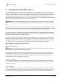
1
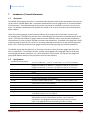
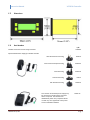
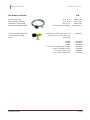
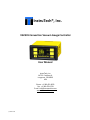
InstruTech®, Inc.
VGC301 Convection Vacuum Gauge Controller
User Manual
InstruTech, Inc.
1475 S. Fordham St.
Longmont, CO 80503
USA
Phone: +1-303-651-0551
Fax: +1-303-678-1754
E-mail [email protected]
www.instrutechinc.com
p/n 000363-108
Copyright © 2012 by InstruTech, Inc.
All rights reserved. No part of this work may be reproduced or transmitted in any form or by any means, electronic or mechanical,
including photocopying and recording, or by any information storage or retrieval system, except as may be expressly permitted in
writing by InstruTech, Inc.
Printed in the United States of America
Convectron® and Granville-Phillips® are registered trademarks of Brooks Automation, Inc. Chelmsford, MA
p/n 000363-108
Instruction Manual
VGC301A Controller
Table of Contents
1
2
3
Introduction / General Information ......................................................................................................3
1.1
Description ....................................................................................................................................3
1.2
Specifications ................................................................................................................................3
1.3
Dimensions ....................................................................................................................................4
1.4
Part Numbers ................................................................................................................................4
Important Safety Information ...............................................................................................................6
2.1
Safety Precautions - General.........................................................................................................6
2.2
Safety Precautions - Service and operation ..................................................................................7
2.3
Electrical Conditions......................................................................................................................7
2.3.1
Proper Equipment Grounding ...............................................................................................7
2.3.2
Electrical Interface and Control .............................................................................................8
2.4
Overpressure and use with hazardous gases ...............................................................................8
2.5
Gases other than Nitrogen / air ....................................................................................................8
Installation ............................................................................................................................................9
3.1
Mechanical Installation .................................................................................................................9
3.2
4
Electrical Installation ...................................................................................................................10
3.2.1
Grounding ............................................................................................................................10
3.2.2
Electrical Connections..........................................................................................................10
Setup and Operation ...........................................................................................................................12
4.1
User Interface Basics ...................................................................................................................12
4.2
Programming...............................................................................................................................12
4.3
Return to Factory Default Settings .............................................................................................14
5
Using the gauge with different gases .................................................................................................15
6
Display .................................................................................................................................................17
6.1
Display - Torr / mTorr ..................................................................................................................17
6.2
Display - mbar .............................................................................................................................18
InstruTech, Inc.
Page 1
Instruction Manual
7
8
Analog Output .....................................................................................................................................19
7.1
Non-Linear Analog Output - Torr / mTorr...................................................................................20
7.2
Non-Linear Analog Output - mbar ..............................................................................................21
7.3
Log-Linear Analog Output - Torr .................................................................................................22
7.4
Log-Linear Analog Output - mbar ...............................................................................................24
RS485 / RS232 serial communications ................................................................................................26
8.1
Device Specific Serial Communication Info.................................................................................26
8.2
9
VGC301A Controller
RS485 / RS232 Command Protocol Summary ............................................................................27
Service .................................................................................................................................................28
9.1
Calibration ...................................................................................................................................28
9.2
Maintenance ...............................................................................................................................28
9.3
Troubleshooting ..........................................................................................................................28
10
Factory Service and Support ...........................................................................................................29
11
Warranty .........................................................................................................................................29
InstruTech, Inc.
Page 2
Instruction Manual
VGC301A Controller
1
Introduction / General Information
1.1
Description
The VGC301 vacuum gauge controller is a convenient and inexpensive power supply and readout instrument for
the InstruTech® CVG101 Worker Bee™ convection-enhanced Pirani vacuum gauge sensor or a Granville-Phillips®
275 Convectron®. The 1/8-DIN housing can be used as a bench top, or mounted in a cutout in an instrument
panel. The VGC301 is powered by user supplied 12 to 30 Vdc, 2 W, or by the InstruTech series PS301 optional
power supplies.
Thermal conductivity gauges measure pressure indirectly by sensing the loss of heat from a sensor to the
surrounding gases. The higher the pressure of the surrounding gas, the more heat is conducted away from the
sensor. Pirani thermal conductivity gauges maintain a sensor (usually a wire) at some constant temperature,
and measure the current or power required to maintain that temperature. A standard Pirani gauge has a useful
measuring range of about 10-4 Torr to 10 Torr. By taking advantage of convection currents that are generated
above 1 Torr, convection-enhanced Pirani gauges increase the measuring range to just above atmosphere.
The VGC301 signals and relay functions are the same as found on similar convection gauge controllers from
other manufacturers. The VGC301 Controller, CVG101 vacuum gauge tube and gauge cable can be directly
interchanged with Brooks Automation, Inc. / Granville-Phillips® 375 controller, 275 Convectron® gauge and
gauge cable (Remote interface, relay and power connectors are different).
1.2
Specifications
measurement range (signal)
display
display engineering units
display update rate
weight
temperature
humidity
altitude
analog output (user-selectable)
serial communications
housing
input power
setpoint relays
connectors
RF/EMI protection
environmental
InstruTech, Inc.
-4
-4
-2
1.0 x 10 to 1000 Torr / 1.3 x 10 to 1333 mbar / 1.3 x 10 Pa to 133 kPa
Bright OLED, 4 digits, user-selectable Torr, mbar, or Pa,
(4 digits from 1100 Torr to 1000 Torr), (3 digits from 999 Torr to 10.0 mTorr),
(2 digits from 9.9 mTorr to 1.0 mTorr ), (1 digit from 0.9 mTorr to 0.1 mTorr)
Torr, mbar, or Pa - user selectable
0.5 sec
9 oz. (250 g)
o
o
operating; 0 to +40 C storage; -40 to +70 C
0 to 95% relative humidity, non-condensing
operating; 6,560 ft. (2,000 m) max
storage; 41,000 ft. (12,500 m) max
a) log-linear 1 to 8 Vdc, 1 V/decade, or b) linear 0 to 10 Vdc
c) non-linear S-curve 0.375 to 5.659 Vdc
RS232 and 2 wire/4 wire RS485 - ASCII protocol
1/8-DIN panel-mount enclosure (aluminum extrusion)
12-30 Vdc, 2 W
two single-pole double-throw relays (SPDT)
1 A at 30 Vdc resistive, or ac non-inductive
gauge: 9-pin D-sub female (mating connector provided as part of the gauge cable)
analog output and serial communications interface: 9-pin D-sub male
relay outputs: 6-pin pluggable terminal block (mating connector included)
power: 2-pin pluggable terminal block (mating connector included)
CE compliant
RoHS compliant
Page 3
Instruction Manual
1.3
Dimensions
1.4
Part Numbers
VGC301A Controller
P/N
VGC301A
VGC301 Convection Vacuum Gauge Controller
Optional PS301 Power Supply for VGC301 controller
with North American AC Plug
PS301-A
with Universal European AC Plug
PS301-EU
with UK AC Plug
PS301-UK
with China AC Plug
P301-C
with Australian AC Plug
PS301-SP
This variation of the PS301 power supply may
be used when an AC plug that is not listed
above is required. The conventional
IEC60320 AC power entry receptacle allows
use with any user supplied AC mains power
cord set available worldwide.
InstruTech, Inc.
PS301-UX
Page 4
Instruction Manual
VGC301A Controller
Part Numbers continued Vacuum Gauge Cable
For connecting the CVG101
Worker Bee™ vacuum gauge
sensor to the VGC301 controller
InstruTech CVG101 Worker Bee
Convection Vacuum Gauge
Sensor
P/N
10 ft. (3 m):
25 ft. (8 m):
50 ft. (15 m):
over 50 ft. or custom lengths:
CB421-1-10F
CB421-1-25F
CB421-1-50F
Consult Factory
Combination 1/8 in. NPT male - 1/2 in. tube
(use 1/8" NPT male or 1/2" O.D. O-ring
compression)
CVG101GA
NW16KF
NW25KF
NW40KF
1 1/3 in. Mini-CF / NW16CF Mini-Conflat®
2 3/4 in. CF / NW35CF Conflat®
1/4 in. Cajon® 4VCR® female
1/2 in. Cajon® 8VCR® female
InstruTech, Inc.
CVG101GB
CVG101GC
CVG101GD
CVG101GE
CVG101GF
CVG101GG
CVG101GH
Page 5
Instruction Manual
2
VGC301A Controller
Important Safety Information
InstruTech has designed and tested this product to provide safe and reliable service, provided it is installed and
operated within the strict safety guidelines provided in this manual. Please read and follow all warnings and
instructions.
WARNING
WARNING
To avoid serious injury or death, follow the safety information in this document. Failure to comply with these
WARNING
safety procedures could result in serious bodily
harm, including death, and or property damage.
Failure to comply with these warnings violates the safety standards of installation and intended use of this
instrument. InstruTech, Inc. disclaims all liability for the customer’s failure to comply with these instructions.
Although every attempt has been made to consider most possible installations, InstruTech cannot anticipate
every contingency that arises from various installations, operation, or maintenance of the controller. If you have
any questions about the safe installation and use of this product, please contact InstruTech.
2.1
Safety Precautions - General
Hazardous voltages are present with this product during normal operation. The product should never be
operated with the enclosure removed unless equivalent protection of the operator from accidental contact with
hazardous internal voltages is provided.
WARNING! There are no operator serviceable parts or adjustments inside the product enclosure. Refer
servicing to service trained personnel.
Do not modify this product or substitute any parts without authorization of qualified InstruTech service trained
personnel. Return the product to an InstruTech qualified service and repair center to ensure that all safety
features are maintained. Do not use this product if unauthorized modifications have been made.
WARNING! Source power must be removed from the product prior to performing any servicing.
After servicing this product, ensure that all safety checks are made by a qualified service person. When
replacement parts are required, ensure that the parts are specified by InstruTech, Inc. Substitutions of nonqualified parts may result in fire, electric shock or other hazards. Use of unauthorized parts or modifications
made to this product will void the warranty.
To reduce the risk of fire or electric shock, do not expose this product to rain or moisture. These products are
not waterproof and careful attention must be paid to not spill any type of liquid onto these products. Do not
use these products if they have been damaged. Immediately contact InstruTech, Inc. to arrange return of the
product if it is damaged.
InstruTech, Inc.
Page 6
Instruction Manual
VGC301A Controller
Due to the possibility of corrosion when used in certain environmental conditions, it is possible that the
product’s safety could be compromised over time. It is important that the product be periodically inspected for
sound electrical connections and equipment grounding. Do not use if the equipment grounding or electrical
insulation has been compromised.
2.2
Safety Precautions - Service and operation
Ensure the enclosure of the VGC301 is connected directly to a good quality earth ground.
Ensure that the vacuum port on which the CVG101 vacuum gauge tube is mounted is electrically grounded.
Use an appropriate power source of 12 to 30 Vdc, 2 W or use InstruTech series PS301 optional power supplies.
Turn off power to the unit before attempting to service the controller.
Turn off power to the unit if a cable or plug is damaged or the product is not operating normally according to
this instruction manual. Contact qualified InstruTech service personnel for any service or troubleshooting
condition that may not be covered by this instruction manual.
It is important that the product be periodically inspected for sound electrical connections and equipment
grounding. Do not use if the equipment grounding or electrical insulation has been compromised.
Do not use if the unit has been dropped or the enclosure has been damaged. Contact InstruTech for return
authorization and instructions for returning the product to InstruTech for evaluation.
2.3
Electrical Conditions
WARNING! When high voltage is present in any vacuum system, a life threatening electrical shock hazard
may exist unless all exposed electrical conductors are maintained at earth ground potential. This applies to all
products that come in contact with the gas contained in vacuum chambers. An electrical discharge within a
gaseous environment may couple dangerous high voltage directly to any ungrounded conductor of electricity. A
person could be seriously injured or killed by coming in contact with an exposed, ungrounded electrical
conductor at high voltage potential. This condition applies to all products that may come in contact with the gas
inside the vacuum chamber (vacuum/pressure containment vessel).
2.3.1 Proper Equipment Grounding
WARNING! Hazardous voltages that could seriously injure or cause death are present in many vacuum
processes. Verify that the vacuum port on which the CVG101 vacuum gauge tube is mounted is electrically
grounded. Consult a qualified Electrician if you are in doubt about your equipment grounding. Proper
grounding of your equipment is essential for safety as well as intended operation of the equipment. The
CVG101 vacuum gauge tube and enclosure of the VGC301 controller must be connected directly to a good
quality earth ground. Use a ground lug on the CVG101 gauge vacuum connection / flange if necessary.
InstruTech, Inc.
Page 7
Instruction Manual
VGC301A Controller
WARNING! In order to protect personnel from electric shock and bodily harm, shield all conductors
which are subject to potential high voltage electrical discharges in or around the vacuum system.
2.3.2 Electrical Interface and Control
It is the user’s responsibility to ensure that the electrical signals from this product and any connections made to
external devices, for example, relays and solenoids, are used in a safe manner. Always double check the system
set-up before using any signals to automate your process. Perform a hazardous operation analysis of your
system design and ensure safeguards and personnel safety measures are taken to prevent injury and property
damage.
2.4
Overpressure and use with hazardous gases
WARNING! Install suitable protective devices that will limit the level of pressure inside your vacuum
chamber to less than what the vacuum chamber system components are capable of withstanding. InstruTech
gauges should not be used at pressures exceeding 1000 Torr absolute pressure.
In cases where an equipment failure could cause a hazardous condition, always implement fail-safe system
operation. For example, use a pressure relief device in an automatic backfill operation where a malfunction
could result in high internal pressures if the pressure relief device was not installed on the chamber.
The CVG101 vacuum gauge tube connected to the VGC301A controller is not intended for use at pressures
above 20 psia (1000 torr); DO NOT exceed 35 psig (< 2 ½ bars) pressure inside the sensor. If your chamber goes
to higher pressures, you should install an isolation valve or pressure relief device to protect the gauge tube from
overpressure conditions. With some fittings, actual safe overpressure conditions may be lower; for example, a
quick-connect, O-ring compression fitting may forcibly release the gauge tube from the vacuum chamber fitting
with only a few psi over local uncorrected barometric (atmospheric) pressure.
CAUTION! If the internal pressure of a vacuum gauge device is allowed to increase above local
uncorrected barometric pressure (atmospheric pressure side), vacuum fittings may release and possible
overpressure conditions may cause leaks that would allow the gas inside the gauge tube to release into the
atmosphere of the surrounding environment. Toxic, pyrophoric and flammable gases are examples of
hazardous gases that if allowed to leak out of the vacuum/pressure containment vessel into the atmospheric
environment, could cause bodily injury and possible damage to equipment. Never expose the gauge tube
internal volume to pressure above local atmospheric pressure when using hazardous gases.
2.5
Gases other than Nitrogen / air
WARNING! Do not attempt to use with gases other than nitrogen (N2) or air without referring to correction
factor data tables.
InstruTech gauges and modules are calibrated for direct readout of nitrogen or air. Do not attempt to use with
other gases such as argon (Ar) or carbon dioxide (CO2) unless accurate conversion data for N2 to other gas is
properly used. Refer to sections titled “Using the gauge with different gases”, “Display” and “Analog Output” for
a more complete discussion.
InstruTech, Inc.
Page 8
Instruction Manual
VGC301A Controller
WARNING! Do not use the convection gauge connected to this device in an explosive atmosphere or in the
presence of flammable gases, vapors or fumes. Do not use this device to measure the pressure of explosive or
combustible gases or gas mixtures. The sensor wire in the gauge normally operates at 125 oC, but if malfunction
should occur, the wire temperature could exceed the ignition temperature of certain combustible gases and gas
mixture. This could cause an explosion which could result in serious injury or death.
3
3.1
Installation
Mechanical Installation
The VGC301 is designed for use on a bench top, or it may be mounted in an instrument control panel.
To mount the VGC301 in a panel:
1. Make a cutout in your instrument control panel as shown in the drawing above. Be sure to allow clearance
behind the panel for the instrument as well
as connectors and cables at the rear of the
instrument
2. Gently pry the front panel bezel loose
and remove.
3. Slide the VGC301 into the panel hole
cutout.
4. On either side of the VGC301 are two
screw-mounting brackets. When the screws
in the front of the instrument are turned
counterclockwise, the hold-down brackets recess out of the way into the VGC301 housing. When these screws
are turned clockwise, the brackets rotate out 90o behind the panel. Tighten these screws until the brackets hold
the VGC301 in place against the panel.
5. Press the front panel bezel back in place.
InstruTech, Inc.
Page 9
Instruction Manual
3.2
VGC301A Controller
Electrical Installation
3.2.1 Grounding
Be sure the vacuum gauge and your vacuum system are properly grounded to protect personnel from shock
and injury. Be aware that some vacuum fittings, especially those with O-rings, may not produce a good
electrical connection between the gauge and the chamber it is connected to.
3.2.2 Electrical Connections
A good recommended practice is to remove power from any cable prior to connecting or disconnecting it.
The InstruTech VGC301 may replace similar controllers from other manufacturers, such as the Granville-Phillips®
375 controller. Many of these other controllers employ the same 9-pin and 15-pin D connectors, but they do
not all use the same signal / pinout configurations. If you wish to use your existing cables, be sure to check
compatibility with the tables on the next page. Rewire your cables as necessary.
Remote I/O &
interface connector
gauge
connector
relay
connector
DC Power
Input
DC Power Input
The VGC301 accepts DC power from 12 to 30 Vdc, 2 W. If the user prefers to use AC power, InstruTech offers
the series PS301 optional power supplies with various AC Plugs.
2-pin pluggable terminal strip (Mating connector: Phoenix p/n 1803578 or InstruTech p/n 000327).
pin number
pin description
1
+12 to +30 V
2
ground
InstruTech, Inc.
Page 10
Instruction Manual
VGC301A Controller
Remote I/O & Interface Connector
9-pin D-sub female (Mating connector: InstruTech p/n 000263 + 000264)
pin number
pin description – 4 Wire RS485
pin description – 2 Wire RS485
1
RS485 RDA (- ) Input
RS485 DATA A (-) Input/output
2
RS485 RDB (+) Input
RS485 DATA B (+) Input/output
3
RS485 TDA (- ) Output
4
RS485 TDB (+) Output
5
RS232 TX
RS232 TX
6
RS232 RX
RS232 RX
7
analog signal output
analog signal output
(non-linear, linear, or log-linear)
(non-linear, linear, or log-linear)
8
signal ground
signal ground
(1)
9
relay disable
relay disable(1)
1. The relays are disabled by applying a continuous ground to pin # 9. This will prevent any switching of the
relay contactors during operation of the VGC301.
Relay Connector
6-pin pluggable terminal strip (Mating connector: Phoenix p/n1803617 or InstruTech p/n 000347)
pin number
pin description
1
relay 1 common
2
relay 1 NC
3
relay 1 NO
4
relay 2 common
5
relay 2 NC
6
relay 2 NO
Gauge cable assembly
P/N CB421-1-XXXF is a custom cable assembly provided in different lengths from InstruTech for connecting the
VGC301 controller to InstruTech CVG101 Worker Bee or Brooks Automation, Inc. / Granville-Phillips® 275
Convectron® vacuum gauge sensor. The cable pin to pin connection is shown below.
VGC301 pin number
1
2
3
4
5
6
7
8
9
InstruTech, Inc.
connects to
CVG101 gauge pin number
CVG101 molded plastic connector
P/N CK431-01
NC
cable shield
3
NC
2
5
1
1
NC
Page 11
Instruction Manual
4
VGC301A Controller
Setup and Operation
User Interface Basics
4.1
The user interface is designed for easy operation and a
natural progression of setup parameters. This section gives a
brief explanation of operation for added clarity.
Programming soft-keys
There are four soft-keys located on the front panel, two on
each side of the display. These keys are used to select and
program the various functions available. During programming
of the VGC301, the display will identify what function each
key represents.
To begin programming, press any one of the four keys. The display will indicate a choice of functions. Press the
key indicated by the function on the display to continue with the programming of the parameter desired. After
setting the various parameters, press the SAVE/EXIT key to save the new setting and return to the main screen.
To continue setting additional parameters, scroll forward with the MORE key until you reach the desired
parameter.
Programming
4.2
SET VAC
NOTICE
When operating in units of either mbars (mbar) or pascals (Pa), you must perform SET ATM
before setting the vacuum reading (SET VAC). See SET ATM below. Failure to do so will result in improper
operation of the gauge. If you change units of measure or reset to factory defaults, then this same procedure
must be followed again if the units of measure are being set to either mbar or Pa.
1. To properly set the vacuum reading (“zero” point), with the CVG101 installed on your vacuum system,
the gauge should be evacuated to a pressure below 1 x 10⁻⁴ Torr.
2. Go to the SET VAC screen. When the vacuum system pressure is below 1 X 10⁻⁴ Torr, press the PRESS TO
SET VAC key. The zero point (displayed pressure reading with gauge exposed to vacuum) is now set.
UNITS [Factory default = TORR]
This should be the first parameter that is set. This will be the units-of-measure (Torr, mbar, Pa) that are used for
all other settings. If your VGC301 has been previously configured and relay setpoints and linear analog output
pressure settings have been programmed, changing units-of-measure will return the relays setpoints and the
linear analog output pressure settings to factory default setting values in Torr. In this case, you must reprogram
the relay setpoints and linear analog output pressure settings in the newly programmed units-of-measure.
InstruTech, Inc.
Page 12
Instruction Manual
VGC301A Controller
SET ATM
1. To set the atmospheric pressure reading (also known as the “span” adjustment), flow nitrogen gas or air
into your closed vacuum chamber to allow the pressure to rise to a known value above 400 Torr.
Alternatively, if your local uncorrected barometric pressure (air) is known, simply vent your vacuum
system chamber to expose the gauge to the local atmospheric pressure.
2. Go to the SET ATM screen. When the desired pressure is stable, adjust the displayed pressure reading
on the VGC301 to the known value using the INCR (increase) or DECR (decrease) keys. Press the
SAVE/EXIT key to save the new atmospheric (span) pressure value.
It is good practice to perform the sequence of checking and adjusting span (ATM) then zero (VAC) and
then, finally re-checking the span setting to ensure that the circuitry is properly balanced for use in
measuring pressure throughout the intended measurement range.
SP1 ON and SP2 ON [Factory default = 100 mTORR]
These setpoints correspond to the pressures at which the relays will turn on (energize). The relays will turn on
when the pressure is below the programmed pressure value. If you are unable to increase the values of SP1 ON
or SP2 ON , you must first go to SP1 OFF or SP2 OFF and increase those values to a number higher than the
values of SP1 ON or SP2 ON you are trying to set.
SET SP1 OFF and SET SP2 OFF [Factory default = 200 mTORR]
These setpoints correspond to the pressures at which the relays will turn of (de-energize). The relays will turn
off when the pressure is above the programmed pressure value. If you are unable to decrease the values of SP1
OFF or SP2 OFF, you must first go to SP1 ON or SP2 ON and decrease those values to a number lower than the
values of SP1 OFF or SP2 OFF you are trying to set.
RS485 ADDR [Factory default = 1]
This is the lower nibble of the one byte RS485 device address. Assuming the address offset (ADDR OFFSET) is
equal to 0, setting the ADDR to a 5 will make the address be 0x05 in hexadecimal. A 15 will set the ADDR to
0x0F in hexadecimal. Note that the address (ADDR) must be used even when sending RS232 commands
RS485 OFFSET [Factory default = 0]
This is the upper nibble of the one byte RS485 address. Assuming the address (ADDR) is 0, setting the address
offset (ADDR OFFSET) to a 5 will make the address be 0x50 hexadecimal. Setting the address offset to 15 will
make the device address be 0xF0 hexadecimal.
ADDRESS
DECIMAL
1
5
15
16
InstruTech, Inc.
┌ -----------------------------BINARY ADDRESS-----------------------------┐
┌ -------------------------------------ONE BYTE-----------------------------------┐
ADDRESS
HEXADECIMAL
(BINARY)
ADDR OFFSET
ADDR
┌Upper nibble┐
┌Lower nibble┐
0000
0001
01
0000
0101
05
0000
1111
0F
0001
0000
F0
Page 13
Instruction Manual
VGC301A Controller
BAUD [Factory default = 19,200]
This sets the baud rate for the RS485 and the RS232 serial communications. The baud rate can be set to various
values through the serial interface or via the front panel soft-keys. The parity can only be changed through the
serial interface command set. When this occurs, the current setting will be shown in the list of choices and can
be re-selected if changed.
RS485 Type [Factory default = 2 WIRE]
Selects 2-wire or 4-wire configuration for RS485 interface.
ANALOG TYPE [Factory default = LOG]
Select “NONLIN” for non-linear (S-Curve) or “LOG” for log-linear or “LINEAR” analog output (See Analog Output
section).
SET LINEAR [Factory default = 0.01 VOLTS to 10 VOLTS corresponding to 1 mTORR to 1 TORR]
This will take the user to four different screens to setup the linear analog output (See Analog Output section).
a) Set the minimum pressure
b) Set the minimum voltage corresponding to the minimum pressure
c) Set the maximum pressure
d) Set the maximum voltage corresponding to the maximum pressure
The linear output voltage can be any value between 0.01 Vdc and 10 Vdc corresponding to pressures between
1 mTorr and 1000 Torr.
INFO
This screen shows the unit firmware version.
4.3
Return to Factory Default Settings
You can reset all values to the original factory default settings by simultaneously pressing the upper left and
upper right soft-keys. The user will then be prompted to “Set Factory Defaults?” Choose Yes or No.
InstruTech, Inc.
Page 14
Instruction Manual
5
VGC301A Controller
Using the gauge with different gases
A thermal conductivity gauge senses heat loss which depends on the thermal conductivity of the gas surrounding the
sensor. Since different gases, and mixtures, have different thermal conductivities, the indicated pressure readings and
outputs will also be different. InstruTech convection gauges (and most other thermal conductivity gauges) are calibrated
using nitrogen (N2). When a gas other than N2 / air is used, correction must be made for the difference in thermal
conductivity between nitrogen (N2) and the gas in use. The charts and tables on the following pages indicate how different
gases affect the display and output from an InstruTech convection gauge.
WARNING! Using a thermal conductivity gauge with gases other than that for which it is calibrated could result in
death or serious injury. Be sure to use gas correction data in this manual when measuring pressures of gases other than
N2 / air.
-4
For N2 the calibration shows excellent agreement between indicated and true pressure throughout the range from 10 to
1000 Torr. At pressures below 1 Torr, the calibration curves for the different gases are similar. The difference in readings
at these low pressures is a constant, a function of the difference between thermal conductivities of the gases.
At pressures above 1 Torr, indicated pressure readings may diverge significantly. At these higher pressures convection
currents in the gauge become the predominant cause of heat loss from the sensor and calibration depends on gauge tube
geometry and mounting position as well as gas properties.
Generally, air and N2 are considered the same with respect to thermal conductivity, but even N 2 and air will exhibit slight
differences in readings at higher pressures. For example, when venting a system to atmosphere using N2, you may see
readings change by 30 to 40 Torr after the chamber is opened and air gradually displaces the N 2 in the gauge. For most
other gases the effect is much more significant and may result in a hazardous condition as described below.
Other considerations when using gases other than N2 / air
Flammable or explosive gases
WARNING! InstruTech convection gauges are neither intrinsically safe nor explosion proof and are not intended for
use in the presence of flammable or explosive gases or vapors.
Under normal conditions the voltages and currents in InstruTech convection gauges are too low to cause ignition of
flammable gases. However, under certain failure conditions, sufficient energy could be generated to cause flammable
vapors or gases to ignite or explode. Thermal conductivity gauges like the InstruTech convection gauges are not
recommended for use with flammable or explosive gases.
Moisture / water vapor
In some processes (lyophilization, for example) the gas composition may not change significantly, except for moisture
content. Water vapor can significantly change the response of a thermal gauge and correction should be made, as you
would for any other gas.
Other contaminants
If your gases condense, coat, or corrode the sensor, the gauge calibration and response to different gases will change.
Generally, if the gauge can be "calibrated" ("zero" and "span" settings), these changes are small enough to be ignored. If
you can’t set zero and span, the gauge should be replaced or return to factory for evaluation and possible cleaning.
InstruTech, Inc.
Page 15
Instruction Manual
VGC301A Controller
Convection Vacuum Gauge
Indicated vs. True Total Pressure
Test Gases - N2, Ar, He
1000
Ar
100
True Total Pressure (Torr)
(capacitance manometer)
N2
10
He
1
0.1
0.01
0.001
0.0001
0.0001
0.001
0.01
0.1
1
10
100
1000
Indicated Pressure (Torr)
(convection gauge)
CVG N2
Convectron N2
CVG Ar
Convectron Ar
Convectron He
CVG He
Gas Correction Chart
The Y- axis of the above chart is actual pressure as measured by a capacitance manometer, a diaphragm gauge
that measures true total pressure independent of gas composition. The X-axis is the pressure reading indicated
by the convection gauge under test. This chart shows readings for an InstruTech convection gauge (CVG) and
Granville-Phillips® Convectron® gauge to illustrate that the difference in the response for both of these types of
gauges is virtually indistinguishable.
CAUTION! Do not assume this data applies to other convection gauges which may or may not be the same.
Refer to the table on the next page and note the following examples:
Ex A: If the gas is nitrogen (N2), when the true total pressure is 500 Torr, the gauge will read 500 Torr.
Ex B: If the gas is argon (Ar), when the true pressure is 100 Torr, the gauge will read about 9 Torr.
If you are backfilling your vacuum system with Ar, when your system reaches a pressure of 760 Torr
true pressure your gauge will be reading about 23 Torr. Continuing to backfill your system, attempting to
increase the reading up to 760 Torr, you will over pressurize your chamber which may present a hazard.
Ex C: If the gas is helium (He), the gauge will read 999 Torr when pressure reaches about 10 Torr true pressure
and opening the chamber to atmosphere prematurely may present other hazards for both people and product.
CAUTION! What these examples illustrate is that using gases other than nitrogen (N2) without using accurate
gas conversion data and other proper precautions could result in injury to personnel and/or damage to
equipment.
Suggested precautions when using gases other than nitrogen (N2):
Install a pressure relief valve or burst disk on your chamber, to protect it from overpressure. Post a warning
label on your gauge readout that states "Do Not Exceed ____ Torr Indicated Pressure" (fill in the blank for
maximum indicated pressure for the gas you use) so that an operator using the gauge will not exceed a safe
pressure.
InstruTech, Inc.
Page 16
Instruction Manual
VGC301A Controller
6
Display
6.1
Display - Torr / mTorr
The table below shows the displayed readings at various pressures for selected gases when engineering units
selected is in Torr/mTorr.
Displayed Pressure Readings vs. True Pressure for selected gases
Pressures shown in bold italic font in the shaded areas are in mTorr.
Pressures shown in normal font and in non-shaded areas are in Torr.
True Total
Pressure
0
0.1
0.2
0.5
1
2
5
10
20
50
100
200
500
1
2
5
10
20
50
100
200
300
400
500
600
700
760
800
900
1000
mTorr
mTorr
mTorr
mTorr
mTorr
mTorr
mTorr
mTorr
mTorr
mTorr
mTorr
mTorr
mTorr
Torr
Torr
Torr
Torr
Torr
Torr
Torr
Torr
Torr
Torr
Torr
Torr
Torr
Torr
Torr
Torr
Torr
N2
Ar
He
O2
CO2
Kr
Freon12
Freon22
D2
Ne
CH4
0.0
0.1
0.2
0.5
1.0
2.0
5.0
10.0
20.0
50.0
100
200
500
1.00
2.00
5.00
10.0
20.0
50.0
100
200
300
400
500
600
700
760
800
900
1000
0.0
0.1
0.2
0.5
0.7
1.4
3.3
6.6
13.1
32.4
64.3
126
312
600
1.14
2.45
4.00
5.80
7.85
8.83
9.79
11.3
13.5
16.1
18.8
21.8
23.7
25.1
28.5
32.5
0.0
0.1
0.2
0.5
0.8
1.6
4.0
8.1
16.1
40.5
82.0
165
435
940
2.22
13.5
OP
OP
OP
OP
OP
OP
OP
OP
OP
OP
OP
OP
OP
OP
0.0
0.1
0.2
0.5
1.0
2.0
5.0
9.7
19.8
49.2
97.2
194
486
970
1.94
4.98
10.3
22.3
77.6
209
295
380
485
604
730
859
941
997
OP
OP
0.0
0.1
0.2
0.5
1.1
2.3
4.4
11.0
22.2
54.9
107
210
489
950
1.71
3.34
4.97
6.59
8.22
9.25
12.3
16.9
22.4
28.7
36.4
46.1
53.9
59.4
79.5
111
0.0
0.1
0.2
0.3
0.4
1.0
2.3
4.8
9.5
23.5
46.8
91.1
217
400
700
1.28
1.78
2.29
2.57
2.74
3.32
3.59
3.94
4.21
4.44
4.65
4.75
4.84
4.99
5.08
0.0
0.1
0.2
0.5
1.5
3.1
7.6
14.7
29.9
72.5
143
275
611
1.05
1.62
2.45
2.96
3.32
3.79
4.68
5.99
6.89
7.63
8.28
8.86
9.42
9.76
9.95
10.5
11.1
0.0
0.1
0.2
0.5
1.5
3.1
7.0
13.5
27.2
69.0
136
262
594
1.04
1.66
2.62
3.39
3.72
4.14
4.91
6.42
7.52
8.42
9.21
9.95
10.7
11.1
11.4
12.0
12.7
0.0
0.1
0.2
0.5
1.3
2.4
6.0
12.1
24.3
60.0
121
250
687
1.55
4.13
246
OP
OP
OP
OP
OP
OP
OP
OP
OP
OP
OP
OP
OP
OP
0.0
0.1
0.2
0.5
0.7
1.5
3.5
7.1
14.1
34.8
70.0
141
359
745
1.59
5.24
21.5
584
OP
OP
OP
OP
OP
OP
OP
OP
OP
OP
OP
OP
0.0
0.1
0.2
0.5
1.7
3.3
7.7
15.3
30.4
77.2
159
315
781
1.60
3.33
7.53
27.9
355
842
OP
OP
OP
OP
OP
OP
OP
OP
OP
OP
OP
Notes:
1) OP = overpressure indication: display will read over pressure
2) Display auto-ranges between Torr and mTorr at 1 Torr
Examples
1) Gas used is nitrogen (N2). Display shows pressure measurement of 10 Torr. True pressure of nitrogen is 10 Torr.
2)
Gas used is argon (Ar). Display shows pressure measurement of 600 mTorr. True pressure of argon is
1 Torr.
3)
Gas used is oxygen (O2). Display shows pressure measurement of 486 mTorr. True pressure of oxygen is 500 mTorr.
InstruTech, Inc.
Page 17
Instruction Manual
VGC301A Controller
Display - mbar
6.2
The table below shows the displayed readings at various pressures for selected gases when engineering units
selected is in mbar.
Displayed Pressure Readings vs. True Pressure for selected gases - Engineering units in mbar
True Pressure
0 mbar
.0001 mbar
.0003 mbar
.0006 mbar
.0013 mbar
.0027 mbar
.0067 mbar
.0133 mbar
.0260 mbar
.0666 mbar
0.130 mbar
0.260 mbar
0.666 mbar
1.33 mbar
2.66 mbar
6.66 mbar
13.3 mbar
26.6 mbar
66.6 mbar
133 mbar
266 mbar
400 mbar
533 mbar
666 mbar
800 mbar
933 mbar
1011 mbar
1060 mbar
1190 mbar
1330 mbar
N2
0.0
.0001
.0003
.0006
.0013
.0027
.0067
.0133
.0260
.0666
0.130
0.260
0.666
1.33
2.66
6.66
13.3
26.6
66.6
133
266
400
533
666
800
933
1011
1060
1019
1330
Ar
0.0
.0001
.0003
.0006
.0009
.0019
.0044
.0088
.0174
.0431
.0857
0.160
0.410
0.790
1.51
3.26
5.33
7.73
10.4
11.7
13.0
15.0
17.9
21.4
25.0
29.0
31.5
33.4
37.9
43.3
He
0.0
.0001
.0003
.0006
.0011
.0021
.0053
.0107
.0214
.0539
0.110
0.210
0.570
1.25
2.95
17.9
OP
OP
OP
OP
OP
OP
OP
OP
OP
OP
OP
OP
OP
OP
O2
0.0
.0001
.0003
.0006
.0013
.0027
.0067
.0129
.0263
.0655
0.120
0.250
0.640
1.29
2.58
6.63
13.7
29.7
103
278
393
506
646
805
973
1140
1250
1320
OP
OP
CO2
0.0
.0001
.0003
.0006
.0015
.0031
.0059
.0146
.0295
.0731
0.140
0.270
0.650
1.26
2.27
4.45
6.62
8.78
10.9
12.3
16.3
22.5
29.8
38.2
48.5
61.4
71.8
79.1
105
147
KR
0.0
.0001
.0003
.0004
.0005
.0013
.0031
.0064
.0126
.0313
.0623
0.120
0.280
0.530
0.930
1.70
2.37
3.05
3.42
3.65
4.42
4.78
5.25
5.61
5.91
6.19
6.33
6.45
6.65
6.77
Freon12
Freon22
0.0
.0001
.0003
.0006
.0020
.0041
.0101
.0195
.0398
.0966
0.190
0.360
0.810
1.39
2.15
3.26
3.94
4.42
5.05
6.23
7.98
9.18
10.1
11.0
11.8
12.5
13.0
13.2
13.9
14.7
0.0
.0001
.0003
.0006
.0020
.0041
.0093
.0179
.0362
.0919
0.180
0.340
0.790
1.38
2.21
3.49
4.51
4.95
5.51
6.54
8.55
10.0
11.2
12.2
13.2
14.2
14.7
15.1
16.0
16.9
D2
0.0
.0001
.0003
.0006
.0017
.0032
.0080
.0161
.0323
.0799
0.160
0.330
0.91
2.06
5.50
327
OP
OP
OP
OP
OP
OP
OP
OP
OP
OP
OP
OP
OP
OP
Ne
0.0
.0001
.0003
.0006
.0009
.0020
.0047
.0095
.0187
.0463
0.100
0.180
0.470
0.990
2.11
6.98
28.6
778
OP
OP
OP
OP
OP
OP
OP
OP
OP
OP
OP
OP
CH4
0.0
.0001
.0003
.0006
.0023
.0044
.0102
.0203
.0405
0.100
0.210
0.410
1.04
2.13
4.43
10.0
37.1
473
1012
OP
OP
OP
OP
OP
OP
OP
OP
OP
OP
OP
Values listed under each gas type are in mbar.
Notes:
1)
OP = Overpressure indication; display will read “overpressure”.
Examples:
1) Gas used is nitrogen. Display shows pressure measurement of 13.3 mbar. True pressure of nitrogen is 13.3 mbar.
2)
Gas used is argon. Display shows pressure measurement of 11.7 mbar. True pressure of argon is 133 mbar.
3)
Gas used is CO2. Display shows pressure measurement of .0731 mbar. True pressure of CO2 is .0666 mbar.
InstruTech, Inc.
Page 18
Instruction Manual
7
VGC301A Controller
Analog Output
The VGC301 provides either a non-linear, log-linear or a
0-10 Vdc linear analog output signal.
Non-Linear Output
The first Convectron® gauge controllers produced a nonlinear output signal of 0.375 to 5.659 Vdc for 0 to 1000
Torr of N2, roughly in the shape of an "S" curve, as shown
at right. Granville-Phillips® adopted the same output
curve for most of their Mini-Convectron® modules and
controllers with non-linear output (although in recent
years, some Granville-Phillips® controllers may output
variations of the original S-curve).
Non-Linear Analog Output
6
Output - Volts
5
4
3
2
The non-linear output from InstruTech convection
gauges, modules and controllers duplicates the original Scurve of 0.375 to 5.659 Vdc for 0 to 1000 Torr.
1
Pressure - Torr
10-3
10-2
10-1
100
10+1
10+2
10+3
The tables shown in section 7.1 and 7.2 contain the
lookup data for converting the non-linear output voltage
into pressure values for nitrogen and various other gases.
Log-Linear Output
Many InstruTech modules and controllers also provide a
log-linear output signal, as an alternative to the nonlinear signal described above. This output, shown at
right, is a 1 Volt per decade signal that may be easier to
use for data logging or control.
8
7
Log-Linear Analog Output
Output - Volts
6
5
4
The table shown in section 7.3 and 7.4 contain the lookup
data and provides the formulas for converting the
log-linear output voltage into pressure values for
nitrogen and various other gases.
3
2
Pressure - Torr
1
10-3
10-2
10-1
100
10+1
10+2
10+3
Linear 0-10 Vdc Analog Output
The VGC301 also provides a linear 0-10 Vdc analog output. The linear output voltage can be any value between 10
mV and 10 V corresponding to displayed pressure between 1 mTorr and 1000 Torr. However, the useful range of the
linear analog output is three decades. For example if the minimum pressure selected is 1 mTorr (1.0 x 10⁻³ Torr) with
a corresponding minimum voltage output of 0.01 volts, then maximum pressure selected to correspond to a
maximum voltage output of 10 volts should not exceed 1.0 Torr. If your application requires the analog output to
cover a pressure range exceeding three decades then consider using the non-linear or the log-linear analog output.
Note that an analog output of less than 0.01 volts (to near 0 volt) may indicate a damaged or faulty sensor.
InstruTech, Inc.
Page 19
Instruction Manual
7.1
VGC301A Controller
Non-Linear Analog Output - Torr / mTorr
Non-Linear analog output for selected gases - Engineering units in Torr/mTorr
True Total
Pressure
0
0.1
0.2
0.5
1
2
5
10
20
50
100
200
500
1
2
5
10
20
50
100
200
300
400
500
600
700
760
800
900
1000
mTorr
mTorr
mTorr
mTorr
mTorr
mTorr
mTorr
mTorr
mTorr
mTorr
mTorr
mTorr
mTorr
Torr
Torr
Torr
Torr
Torr
Torr
Torr
Torr
Torr
Torr
Torr
Torr
Torr
Torr
Torr
Torr
Torr
N2
0.3751
0.3759
0.3768
0.3795
0.3840
0.3927
0.4174
0.4555
0.5226
0.6819
0.8780
1.1552
1.6833
2.2168
2.8418
3.6753
4.2056
4.5766
4.8464
4.9449
5.0190
5.1111
5.2236
5.3294
5.4194
5.4949
5.5340
5.5581
5.6141
5.6593
Ar
0.3750
0.3757
0.3760
0.3780
0.3810
0.3870
0.4030
0.4290
0.4770
0.5950
0.7450
0.9620
1.3860
1.8180
2.3330
3.0280
3.4800
3.8010
4.0370
4.1220
4.1920
4.2830
4.3860
4.4770
4.5500
4.6110
4.6430
4.6630
4.7060
4.7450
He
0.3750
0.3755
0.3765
0.3790
0.3820
0.3890
0.4090
0.4410
0.4970
0.6370
0.8140
1.0680
1.5890
2.1640
2.9390
4.3870
5.7740
7.3140
O2
0.3750
0.3760
0.3770
0.3800
0.3840
0.3920
0.4170
0.4530
0.5210
0.6790
0.8680
1.1410
1.6640
2.1950
2.8140
3.6720
4.2250
4.6200
4.9160
5.0260
5.1060
5.2000
5.3150
5.4220
5.5150
5.5920
5.6330
5.6580
5.7130
5.7620
CO2
0.3750
0.3760
0.3770
0.3810
0.3850
0.3950
0.4120
0.4620
0.5360
0.7050
0.9000
1.1790
1.6680
2.1720
2.6950
3.3160
3.6700
3.9030
4.0710
4.1540
4.3360
4.5020
4.6210
4.7080
4.7750
4.8300
4.8600
4.8770
4.9190
4.9550
Kr
0.3750
0.3755
0.3768
0.3772
0.3790
0.3840
0.3950
0.4150
0.4510
0.5440
0.6680
0.8470
1.1940
1.5360
1.9210
2.4290
2.7340
2.9660
3.0750
3.1340
3.2690
3.3840
3.4660
3.5260
3.5730
3.6130
3.6320
3.6450
3.6740
3.6900
Freon12
0.3750
0.3760
0.3780
0.3820
0.3880
0.4010
0.4370
0.4880
0.5810
0.7780
1.0090
1.3150
1.8260
2.2570
2.6470
3.0290
3.2040
3.3080
3.4300
3.6180
3.8270
3.9380
4.0160
4.0760
4.1240
4.1660
4.1900
4.2030
4.2370
4.2700
Freon22
0.3750
0.3760
0.3780
0.3810
0.3880
0.4000
0.4320
0.4800
0.5660
0.7640
0.9900
1.2910
1.8050
2.2470
2.6660
3.0900
3.3300
3.4140
3.5090
3.6600
3.8830
4.0050
4.0880
4.1510
4.2030
4.2470
4.2710
4.2860
4.3210
4.3540
D2
0.3750
0.3760
0.3770
0.3810
0.3860
0.3960
0.4250
0.4700
0.5490
0.7270
0.9440
1.2650
1.9140
2.6030
3.5080
5.0590
6.3610
Ne
0.3750
0.3757
0.3763
0.3782
0.3810
0.3880
0.4050
0.4330
0.4840
0.6080
0.7680
1.0020
1.4690
1.9760
2.6310
3.7150
4.6050
5.4060
6.1590
6.4830
6.6610
6.7260
6.7670
6.8030
6.8430
6.8900
6.9200
6.9420
7.0000
7.0560
CH4
0.3750
0.3766
0.3780
0.3825
0.3896
0.4030
0.4380
0.4920
0.5840
0.7960
1.0530
1.3920
2.0140
2.6320
3.3130
4.6990
5.1720
5.5830
5.7200
5.8600
6.1030
6.3420
6.5190
6.6420
Values listed under each gas type are in volts.
Note: By design, these values are identical to the outputs from Brooks Automation, Inc. / Granville-Phillips®
Convectron® gauges, Mini-Convectron® modules and controllers so that equivalent units can be interchanged
without affecting your process system or software.
An analog output of less than 0.01 volts to near 0 volt indicates a damaged or faulty sensor.
InstruTech, Inc.
Page 20
Instruction Manual
7.2
VGC301A Controller
Non-Linear Analog Output - mbar
Non-Linear analog output for selected gases - Engineering units in mbar
True
Pressure
N2
Ar
He
O2
CO2
KR
Freon12
Freon22
D2
Ne
CH4
0 mbar
0.3751
0.375
0.375
0.375
0.375
0.375
0.375
0.375
0.375
0.375
0.375
.0001 mbar
0.3759
0.3757
0.376
0.376
0.376
0.376
0.376
0.376
0.376
0.3757
0.3766
.0003 mbar
0.3768
0.376
0.377
0.377
0.377
0.377
0.378
0.378
0.377
0.3763
0.378
.0006 mbar
0.3795
0.378
0.379
0.38
0.381
0.377
0.382
0.381
0.381
0.3782
0.3825
.0013 mbar
0.384
0.381
0.382
0.384
0.385
0.379
0.388
0.388
0.386
0.381
0.3896
.0027 mbar
0.3927
0.387
0.389
0.392
0.395
0.384
0.401
0.4
0.396
0.388
0.403
.0067 mbar
0.4174
0.403
0.409
0.417
0.412
0.395
0.437
0.432
0.425
0.405
0.438
.0133 mbar
0.4555
0.429
0.441
0.453
0.462
0.415
0.488
0.48
0.47
0.433
0.492
.0266 mbar
0.5226
0.477
0.497
0.521
0.536
0.451
0.581
0.566
0.549
0.484
0.584
.0660 mbar
0.6819
0.595
0.637
0.679
0.705
0.544
0.778
0.764
0.727
0.608
0.796
0.13 mbar
0.878
0.745
0.814
0.868
0.9
0.668
1.009
0.99
0.944
0.768
1.053
0.26 mbar
1.1552
0.962
1.068
1.141
1.179
0.847
1.315
1.291
1.265
1.002
1.392
0.66 mbar
1.6833
1.386
1.589
1.664
1.668
1.194
1.826
1.805
1.914
1.469
2.014
1.33 mbar
2.2168
1.818
2.164
2.195
2.172
1.536
2.257
2.247
2.603
1.976
2.632
2.66 mbar
2.8418
2.333
2.939
2.814
2.695
1.921
2.647
2.666
3.508
2.631
3.313
6.66 mbar
3.6753
3.028
4.387
3.672
3.316
2.429
3.029
3.09
5.059
3.715
13.3 mbar
4.2056
3.48
5.774
4.225
3.67
2.734
3.204
3.33
6.361
4.605
4.699
26.6 mbar
4.5766
3.801
7.314
4.62
3.903
2.966
3.308
3.414
5.406
5.172
66.6 mbar
4.8464
4.037
4.916
4.071
3.075
3.43
3.509
6.159
5.583
133 mbar
4.9449
4.122
5.026
4.154
3.134
3.618
3.66
6.483
5.72
266 mbar
5.019
4.192
5.106
4.336
3.269
3.827
3.883
6.661
5.86
400 mbar
5.1111
4.283
5.2
4.502
3.384
3.938
4.005
6.726
533 mbar
5.2236
4.386
5.315
4.621
3.466
4.016
4.088
6.767
666 mbar
5.3294
4.477
5.422
4.708
3.526
4.076
4.151
6.803
800 mbar
5.4194
4.55
5.515
4.775
3.573
4.124
4.203
6.843
933 mbar
5.4949
4.611
5.592
4.83
3.613
4.166
4.247
6.89
1010 mbar
5.534
4.643
5.633
4.86
3.632
4.19
4.271
6.92
1060 mbar
5.5581
4.663
5.658
4.877
3.645
4.203
4.286
6.942
1190 mbar
5.6141
4.706
5.713
4.919
3.674
4.237
4.321
7
1330 mbar
5.6593
4.745
5.762
4.955
3.69
4.270
4.354
7.056
6.103
6.342
6.519
6.642
Values listed under each gas type are in volts.
Note: By design, these values are identical to the outputs from Brooks Automation, Inc. / Granville-Phillips®
Convectron® gauges, Mini-Convectron® modules and controllers so that equivalent units can be interchanged
without affecting your process system or software.
An analog output of less than 0.01 volts to near 0 volt indicates a damaged or faulty sensor.
InstruTech, Inc.
Page 21
Instruction Manual
7.3
VGC301A Controller
Log-Linear Analog Output - Torr
Log-Linear analog output for selected gases - Engineering units in Torr
True Pressure
(Torr)
0.0001
0.0002
0.0005
0.0010
0.0020
0.0050
0.0100
0.0200
0.0500
0.1000
0.2000
0.5000
1.0000
2.0000
5.0000
10.0000
20.0000
50.0000
100.0000
200.0000
300.0000
400.0000
500.0000
600.0000
700.0000
760.0000
800.0000
900.0000
1000.0000
N2
Ar
He
O2
1.000
1.301
1.699
2.000
2.301
2.699
3.000
3.301
3.699
4.000
4.301
4.699
5.000
5.301
5.699
6.000
6.301
6.699
7.000
7.301
7.477
7.602
7.699
7.778
7.845
7.881
7.903
7.954
8.000
1.000
1.301
1.699
1.845
2.146
2.519
2.820
3.117
3.511
3.808
4.100
4.494
4.778
5.057
5.389
5.602
5.763
5.895
5.946
5.991
6.053
6.130
6.207
6.274
6.338
6.375
6.400
6.455
6.512
1.000
1.301
1.699
1.903
2.204
2.602
2.908
3.207
3.607
3.914
4.217
4.638
4.973
5.346
6.130
8.041
8.041
8.041
8.041
8.041
8.041
8.041
8.041
8.041
8.041
8.041
8.041
8.041
8.041
1.000
1.301
1.699
2.000
2.301
2.699
2.987
3.297
3.692
3.988
4.288
4.687
4.987
5.288
5.697
6.013
6.348
6.890
7.320
7.470
7.580
7.686
7.781
7.863
7.934
7.974
7.999
8.041
8.041
CO2
1.000
1.301
1.699
2.041
2.362
2.643
3.041
3.346
3.740
4.029
4.322
4.689
4.978
5.233
5.524
5.696
5.819
5.915
5.966
6.090
6.228
6.350
6.458
6.561
6.664
6.732
6.774
6.900
7.045
Kr
1.000
1.301
1.477
1.602
2.000
2.362
2.681
2.978
3.371
3.670
3.960
4.336
4.602
4.845
5.107
5.250
5.360
5.410
5.438
5.521
5.555
5.595
5.624
5.647
5.667
5.677
5.685
5.698
5.706
Freon12
1.000
1.301
1.699
2.176
2.491
2.881
3.167
3.476
3.860
4.155
4.439
4.786
5.021
5.210
5.389
5.471
5.521
5.579
5.670
5.777
5.838
5.883
5.918
5.947
5.974
5.989
5.998
6.021
6.045
Freon22
1.000
1.301
1.699
2.176
2.491
2.845
3.130
3.435
3.839
4.134
4.418
4.774
5.017
5.220
5.418
5.530
5.571
5.617
5.691
5.808
5.876
5.925
5.964
5.998
6.029
6.045
6.057
6.079
6.104
D2
Ne
1.000
1.301
1.699
2.114
2.380
2.778
3.083
3.386
3.778
4.083
4.398
4.837
5.190
5.616
7.391
8.041
8.041
8.041
8.041
8.041
8.041
8.041
8.041
8.041
8.041
8.041
8.041
8.041
8.041
1.000
1.301
1.699
1.845
2.176
2.544
2.851
3.149
3.542
3.845
4.149
4.555
4.872
5.201
5.719
6.332
7.766
8.041
8.041
8.041
8.041
8.041
8.041
8.041
8.041
8.041
8.041
8.041
8.041
CH4
1.000
1.301
1.699
2.230
2.519
2.886
3.185
3.483
3.888
4.201
4.498
4.893
5.204
5.522
5.877
6.446
7.550
7.925
8.041
8.041
8.041
8.041
8.041
8.041
8.041
8.041
8.041
8.041
8.041
Values listed under each gas type are in volts.
The log-linear output signal and pressure are related by the following formulas:
P = 10(V - 5)
V = log10(P) + 5
where P is the pressure in torr, and V is the output signal in volts.
An analog output of less than 0.01 volts to near 0 volt indicates a damaged or faulty sensor.
The chart on the following page shows the graphical results of the table and formulas given above for nitrogen.
True pressure (N2) is plotted on the X-axis with a log scale. The output signal is plotted on the Y-axis on a linear
scale.
InstruTech, Inc.
Page 22
Instruction Manual
VGC301A Controller
Log-Linear Analog Output Voltage vs Pressure
9
8
7
Output Signal (Volts)
6
5
4
3
2
1
0
0.0001
0.001
0.01
0.1
1
10
100
1000
Pressure (Torr)
Chart of the calculated pressures using the formulas and data for the log-linear
output signal for nitrogen from the previous page.
InstruTech, Inc.
Page 23
Instruction Manual
7.4
VGC301A Controller
Log-Linear Analog Output - mbar
Log-Linear analog output for selected gases - Engineering units in mbar
True
Pressure
(mbar)
N2
Ar
He
O2
CO2
KR
Freon12
Freon22
0.0001
0.0002
0.0005
0.0010
0.0020
0.0050
0.0100
0.0200
0.0500
0.1000
0.2000
0.5000
1.0000
2.0000
5.0000
10.0000
20.0000
50.0000
100.0000
200.0000
300.0000
400.0000
500.0000
600.0000
700.0000
760.0000
800.0000
900.0000
1000.0000
1100.0000
1200.0000
1300.0000
1333.0000
1.000
1.301
1.699
2.000
2.301
2.699
3.000
3.301
3.699
4.000
4.301
4.699
5.000
5.301
5.699
6.000
6.301
6.699
7.000
7.301
7.477
7.602
7.699
7.778
7.845
7.881
7.903
7.954
8.000
8.041
8.079
8.114
8.125
1.000
1.301
1.699
1.903
2.146
2.524
2.820
3.188
3.512
3.809
4.103
4.495
4.784
5.064
5.404
5.633
5.815
5.969
6.045
6.093
6.131
6.178
6.237
6.295
6.349
6.380
6.399
6.488
6.494
6.539
6.580
6.624
6.636
1.000
1.301
1.699
1.938
2.204
2.602
2.908
3.208
3.607
3.928
4.217
4.634
4.962
5.324
6.070
8.125
8.125
8.125
8.125
8.125
8.125
8.125
8.125
8.125
8.125
8.125
8.125
8.125
8.125
8.125
8.125
8.125
8.125
1.000
1.301
1.699
2.000
2.301
2.699
2.991
3.294
3.693
3.989
4.288
4.686
4.987
5.288
5.695
6.008
6.337
6.862
7.282
7.526
7.625
7.705
7.786
7.861
7.928
7.965
7.988
8.042
8.092
8.125
8.125
8.125
8.125
1.000
1.301
1.699
2.028
2.355
2.672
3.012
3.345
3.741
4.033
4.325
4.696
4.982
5.249
5.550
5.743
5.886
6.002
6.065
6.157
6.253
6.353
6.448
6.532
6.611
6.658
6.687
6.766
6.847
6.936
7.028
7.140
7.169
1.000
1.301
1.523
1.668
1.970
2.370
2.675
2.979
3.372
3.671
3.963
4.341
4.614
4.865
5.141
5.309
5.433
5.514
5.548
5.606
5.654
5.679
5.710
5.734
5.754
5.765
5.772
5.787
5.799
5.812
5.822
5.828
5.830
1.000
1.301
1.699
2.125
2.487
2.883
3.172
3.473
3.863
4.157
4.445
4.798
5.044
5.250
5.447
5.556
5.621
5.680
5.751
5.851
5.918
5.962
5.996
6.025
6.050
6.063
6.072
6.092
6.111
6.128
6.146
6.164
6.169
1.000
1.301
1.699
2.125
2.487
2.855
3.136
3.434
3.837
4.136
4.424
4.783
5.037
5.255
5.471
5.602
5.675
5.722
5.780
5.877
5.950
6.000
6.038
6.070
6.097
6.112
6.122
6.146
6.167
6.187
6.204
6.222
6.228
D2
1.000
1.301
1.699
2.080
2.392
2.778
3.082
3.385
3.779
4.082
4.393
4.828
5.174
5.579
7.288
8.125
8.125
8.125
8.125
8.125
8.125
8.125
8.125
8.125
8.125
8.125
8.125
8.125
8.125
8.125
8.125
8.125
8.125
Ne
CH4
1.000
1.301
1.699
1.903
2.166
2.551
2.849
3.150
3.543
3.844
4.148
4.553
4.867
5.192
5.696
6.252
7.608
8.125
8.125
8.125
8.125
8.125
8.125
8.125
8.125
8.125
8.125
8.125
8.125
8.125
8.125
8.125
8.125
1.000
1.301
1.699
2.167
2.523
2.893
3.186
3.484
3.886
4.197
4.500
4.893
5.201
5.517
5.877
6.374
7.409
7.930
8.125
8.125
8.125
8.125
8.125
8.125
8.125
8.125
8.125
8.125
8.125
8.125
8.125
8.125
8.125
Values listed under each gas type are in volts.
The log-linear output signal and pressure are related by the following formulas:
P = 10(V - 5)
V = log10(P) + 5
where P is the pressure in mbar, and V is the output signal in volts.
An analog output of less than 0.01 volts to near 0 volt indicates a damaged or faulty sensor.
The chart on the following page shows the graphical results of the table and formulas given above for nitrogen.
True pressure (N2) is plotted on the X-axis with a log scale. The output signal is plotted on the Y-axis on a linear scale.
InstruTech, Inc.
Page 24
Instruction Manual
VGC301A Controller
Chart of the calculated pressures using the formulas and data for the log-linear
output signal for nitrogen from the previous page.
InstruTech, Inc.
Page 25
Instruction Manual
8
8.1
VGC301A Controller
RS485 / RS232 serial communications
Device Specific Serial Communication Info
The standard VGC301 model provides RS232 / RS485 serial communications. The following information and the
RS485 / RS232 command protocol summary listed on the next page should be used to set serial communications
with the device.
1. Default settings are 19,200 baud rate, 8 data bits, No Parity, 1 stop bit [Factory default; 19,200, 8, N, 1].
2. The baud rate can be set to different values through the serial interface command set or the front panel
push buttons.
3. The parity can be changed only through the serial interface command set and the number of data bits
will change according to the parity selected.
4. The stop bit is always 1.
5. All Responses are 13 characters long.
6. xx is the address of the device (00 thru FF).
7. <CR> is a carriage return.
8. _ is a space.
9. The ‘z’ in the set or read trip point commands is a + or -. The plus is the ‘turns on below’ point and the
minus is the ‘turns off above’ point.
10. All commands sent to the controller start with a ‘#’ character, and all responses from the controller start
with a ‘*’ character.
11. This protocol was designed to be 100% compatible with the Granville-Phillips® Mini-Convectron®.
12. A valid address must be used even in RS232 commands [Factory default = 1].
InstruTech, Inc.
Page 26
Instruction Manual
8.2
VGC301A Controller
RS485 / RS232 Command Protocol Summary
COMMAND
READ
BRIEF DESCRIPTION
Read the current pressure in Torr
SET ADDR
OFFSET
SET SPAN
Set the communications (RS485)
address offset (upper nibble) (1)
Set the span or atmosphere
calibration point
Set the zero or vacuum calibration
point
Set the ‘turns on below’ pressure
point for relay #1 and set the
‘turns off above’ pressure point
for relay #1.
Set the ‘turns on below’ pressure
point for relay #2 and set the
‘turns off above’ pressure point
for relay #2.
Read the ‘turns on below’
pressure point for relay #1 and
read the ‘turns off above’
pressure point for relay #1.
Read the ‘turns on below’
pressure point for relay #2 and
read the ‘turns off above’
pressure point for relay #2.
Read the revision number of the
firmware.
Force unit to return ALL settings
back to the way the factory
programmed them before
shipment. (1)
Set the communications baud rate
for RS485 and RS232. (1)
Set the communications to NO
parity, 8 bits for the RS485 and
RS232. (1)
Set the communications to ODD
parity, 7 bits for the RS485 and
RS232. (1)
Set the communications to EVEN
parity, 7 bits for the RS485/
RS232. (1)
Reset the device. (required to
complete some of the
commands.)
SET ZERO
SET TRIP POINT
#1
SET TRIP POINT
#2
READ TRIP
POINT #1
READ TRIP
POINT #2
READ SW
VERSION
SET FACTORY
DEFAULTS
SET BAUD RATE
SET NO PARITY
SET ODD PARITY
SET EVEN
PARITY
RESET
COMMAND SYNTAX
#xxRD<CR>
(eg: #01RD<CR>)
#xxSAxx<CR>
(eg: #01SA20<CR>)
#xxTSy.yyEzyy<CR>
(eg: #01TS7.60E+02)
#xxTZy.yyEzyy<CR>
(eg: #01TZ0.00E-04<CR>)
#xxSLzy.yyEzyy<CR>
(eg: #01SL+4.00E+02<CR>)
(eg: #01SL-5.00E+02<CR>)
RESPONSE
*xx_y.yyEzyy<CR>
(eg: *01_7.60E+02<CR>)
*xx_PROGM_OK<CR>
#xxSHzy.yyEzyy<CR>
(eg: #01SH+4.00E+02<CR>)
(eg: #01SH-5.00E+02<CR>)
*xx_PROGM_OK<CR>
#xxRLz<CR>
(eg: #01RL+<CR>)
(eg: #01RL-<CR>)
*xx_y.yyEzyy<CR>
(eg: *01_7.60E+02<CR>)
#xxRHz<CR>
(eg: #01RH+<CR>)
(eg: #01RH-<CR>)
*xx_y.yyEzyy<CR>
(eg: *01_7.60E+02<CR>)
#xxVER<CR>
(eg: #01VER<CR>)
#xxFAC<CR>
(eg: #01FAC<CR>)
*xx_mmnnv-vv
(eg: *0105041-00)
*xx_PROGM_OK<CR>
#xxSByyyyy<CR>
(eg: #01SB19200<CR>)
#xxSPN<CR>
(eg: #01SPN<CR>)
*xx_PROGM_OK<CR>
#xxSPO<CR>
(eg: #01SPO<CR>)
*xx_PROGM_OK<CR>
#xxSPE<CR>
(eg: #01SPE<CR>)
*xx_PROGM_OK<CR>
#xxRST<CR>
(eg: #01RST<CR>)
No response
*xx_PROGM_OK<CR>
*xx_PROGM_OK<CR>
*xx_`PROGM_OK<CR>
*xx_PROGM_OK<CR>
(1) Commands marked with a (1) under the “BRIEF DESCRIPTION” column will not take effect until after RESET
command is sent or power is cycled.
InstruTech, Inc.
Page 27
Instruction Manual
9
9.1
VGC301A Controller
Service
Calibration
Every InstruTech CVG101 sensor is calibrated prior to shipment using nitrogen (N2). However, you can calibrate the
instrument by adjusting zero and span (atmosphere) using the procedure described previously in section 4.2 titled
“Programming”. Zero and span (atmosphere) calibration affect the displayed value and the output signal. Zero calibration
-4
-3
optimizes performance of the gauge when operating at a low pressure range of 1 x 10 Torr to 1 x 10 Torr. If your
-3
minimum operating pressure is higher than 1 x 10 Torr, it is not normally necessary to perform calibration at zero and thus
-4
span calibration should be adequate. If you are able to evacuate your system to below 1 x 10 Torr, it is always a good
practice to check and set zero if necessary. This will also improve performance in cases where gauge contamination is
-4
-4
causing higher readings than 1 x 10 Torr even though the system has been evacuated to below 1 x 10 Torr. Care should
be exercised when using gases other than nitrogen (N2) / air.
9.2
Maintenance
In general, maintenance is not required for your InstruTech sensor and controller. Periodic performance checks may be
done by comparing the sensor to a known reference standard.
9.3
Troubleshooting
Indication
Possible Cause
Possible Solution
Display is off / blank
No power
Check power supply & power cable
Readings appear very different from
expected pressure
The process gas is different from the gas
used to calibrate the CVG101 gauge
Correct readings for different gas thermal
conductivity. See section 5 on using the gauge with
different gases
CVG101 gauge has not been calibrated
or has been calibrated incorrectly
Check that zero and span are adjusted correctly
Loose cables or connections
Check and tighten connections
Contamination
Inspect the CVG101 for signs of contamination
such as particles, deposits, discoloration on gauge
inlet. Return to factory for possible cleaning
Vibration
Ensure gauge is not mounted where excessive
vibration is present
Gauge cannot be calibrated - zero and
span can’t be adjusted
Contamination
Return the CVG101 to factory for possible cleaning
Sensor failure for other cause
Replace the CVG101
Setpoint does not actuate
Incorrect setup
Check setpoint setup
Display shows “Sensor Bad”
Sensor wire damaged
Replace the CVG101
Display shows “overpressure”
System pressure over 1000 Torr
Reduce pressure
Faulty electronics
Repair or replace the VGC301 electronics
Atmospheric pressure reads too high
and can’t be set to correct value
Contamination
Return the CVG101 to factory for possible cleaning
Sensor wire damaged
Replace the CVG101
Atmospheric pressure reads too low
and can’t be set to correct value
Sensor wire damaged
Replace the CVG101
Contamination
Return the CVG101 to factory for possible cleaning
Readings are noisy or erratic
InstruTech, Inc.
Page 28
Instruction Manual
10
VGC301A Controller
Factory Service and Support
If you need help setting up, operating, troubleshooting, or obtaining a return materials authorization number
(RMA number) to return the controller for diagnosis, please contact us during normal business hours (8:00am to
5:00pm Mountain time) Monday through Friday, at 303-651-0551. Or e-mail us at [email protected].
If you intend to also return the vacuum gauge sensor used with the controller, for the safety of our employees,
you must download, complete and submit a material disclosure form from our website at
www.instrutechinc.com Please use this form to provide a history of the gauge detailing what gases have been
used. We cannot accept gauges that have been exposed to hazardous materials.
11
Warranty
SELLER warrants that its products are free of defects in workmanship and material and fit for the uses set forth
in SELLER's catalog or product specifications, under the normal use and service for which they are intended.
The entire warranty obligation of SELLER is for the repair or replacement, at SELLER's option, of products or
parts (examination of which shall disclose to SELLER's satisfaction that it is defective) returned, to SELLER's plant,
properly identified within five years (unless otherwise noted) after the date of shipment from InstruTech Plant.
BUYER must obtain the approval of SELLER and a return authorization number prior to shipment.
Alteration or removal of serial numbers or other identification marks renders this warranty void. The warranty
does not apply to products or components which have been abused, altered, operated outside of the
environmental specifications of the product, improperly handled or installed, or units which have not been
operated in accordance with SELLER's instructions. Furthermore the warranty does not apply to products that
have been contaminated, or when the product or part is damaged during the warranty period due to causes
other than ordinary wear and tear to the product including, but not limited to, accidents, transportation,
neglect, misuse, use of the product for any purpose other than that for which it was designed.
THIS WARRANTY IS EXCLUSIVE AND IN LIEU OF ALL OTHER WARRANTIES, EXPRESS OR IMPLIED, INCLUDING ANY
IMPLIED WARRANTY OF MERCHANTABILITY OR FITNESS FOR A PARTICULAR PURPOSE. THIS WARRANTY EXTENDS
ONLY IN FAVOR OF THE ORIGINAL BUYER. THE BUYER'S SOLE REMEDY SHALL BE THE REPAIR OR REPLACEMENT, AS IS
EXPRESSLY PROVIDED HEREIN, OF ANY WARRANTED DEFECTIVE PRODUCT OR PART, AND UNDER NO CIRCUMSTANCE
SHALL SELLER BE LIABLE TO BUYER OR ANYONE ELSE FOR ANY CONSEQUENTIAL DAMAGES TO PERSONS OR
PROPERTY, FOR INCIDENTAL DAMAGES OR LOSS OF TIME, FOR ANTICIPATED OR LOST PROFITS, OR ANY OTHER LOSS
INCURRED BY THE BUYER RELATED TO THE PRODUCT COVERED BY THIS WARRANTY. THIS EXCLUSIVE REMEDY SHALL
NOT BE DEEMED TO HAVE FAILED OF ITS ESSENTIAL PURPOSE SO LONG AS SELLER IS WILLING AND ABLE TO REPAIR
OR REPLACE DEFECTIVE PARTS IN THE PRESCRIBED MANNER. THIS LIMITED WARRANTY MAY NOT BE MODIFIED BY
SELLER UNLESS SUCH MODIFICATION OR WAIVER IS IN WRITING, EXECUTED BY AN AUTHORIZED OFFICER OF SELLER.
InstruTech, Inc.
Page 29
InstruTech®, Inc.
1475 S. Fordham St.
Longmont, CO 80503
USA
Phone +1-303-651-0551
Fax +1-303-678-1754
E-mail [email protected]
www.instrutechinc.com
p/n 000363-108