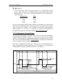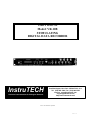
1
USER’S MANUAL
Model: VR-10B
STIMULATING
DIGITAL DATA RECORDER
InstruTECH
Precision Instrumentation for Biological Research
20 Vanderventer Avenue, Suite 101E
Port Washington, New York 11050-3752 U. S. A.
Tel: (516) 883-1300 Fax: (516) 883-1558
Internet: [email protected]
[email protected]
http://www.instrutech.com/
©1995 - 1998 Instrutech Corporation
Revision2.0: 7/7/98
INSTRUTECH CORPORATION
VR-10B USER’S MANUAL
Table of Contents
Table of Contents.............................................................................................................2
Table of Figures ...............................................................................................................4
1 Declaration of Conformity for the European Union ....................................................5
2 General Information.....................................................................................................6
2.1 Product intended usage .................................................................................6
2.2 Safe Environmental Conditions ....................................................................6
2.3 Power requirements ......................................................................................6
2.4 Changing the fuse..........................................................................................6
2.5 Cleaning ........................................................................................................7
2.6 Explanation of symbols.................................................................................8
2.7 Accessories ...................................................................................................9
2.8 Unpacking .....................................................................................................9
2.9 Purchase Information ....................................................................................10
2.10 Technical Specifications .............................................................................11
2.11 Description..................................................................................................13
2.12 Built in Stimulation Capability ...................................................................14
2.13 Video Cassette Recorders ...........................................................................14
2.14 Video Tapes ................................................................................................15
2.15 Recording Speed .........................................................................................16
3 Controls and Functions ................................................................................................17
3.1 Front Panel Controls .....................................................................................17
3.2 Rear Panel Controls ......................................................................................21
4 Operating the VR-10B .................................................................................................23
4.1 Initial connection and setup ..........................................................................23
4.2 Making Recordings .......................................................................................25
4.3 Playing back recordings ................................................................................26
4.4 The Audio Amplifier.....................................................................................27
4.5 Reducing the Audio Amplifier Output .........................................................28
4.6 Applications ..................................................................................................28
4.7 Optional Computer Interface ........................................................................29
2
INSTRUTECH CORPORATION
VR-10B USER’S MANUAL
5 Interfacing Connections ...............................................................................................31
5.1 Parallel Interface Connector..........................................................................31
5.2 Expansion Connector ....................................................................................33
5.3 The Serial Port ..............................................................................................35
6 The VR-10B I/O Panel (optional accessory)................................................................36
6.1 Description....................................................................................................36
6.2 Front Panel Connections ...............................................................................36
6.3 Rear Panel Connections ................................................................................37
7 Using the VR-10B Stimulator......................................................................................38
7.1 Optional STIM-10B Control Panel Software................................................38
7.2 The VR-10B Stimulator Inputs and Outputs.................................................38
7.3 The Stimulator Control Stream.....................................................................39
7.4 Example stimulation data stream ..................................................................43
8 Trouble shooting Guide ...............................................................................................46
9 Calibration....................................................................................................................48
9.1 Why Recalibrate?..........................................................................................48
9.2 Recalibration Procedure................................................................................48
9.3 LC Display Contrast......................................................................................51
10 Warranty Information.................................................................................................52
10.1 Limited Warranty ........................................................................................52
10.2 Obtaining Warranty Service........................................................................52
11 Other Products available from Instrutech Corporation ..............................................53
3
INSTRUTECH CORPORATION
VR-10B USER’S MANUAL
Table of Figures
Figure 1. Explanation of symbols ....................................................................................8
Figure 2. LCD Display Record Mode .............................................................................17
Figure 3. LCD Display Playback Mode ..........................................................................17
Figure 4. Front Panel.......................................................................................................21
Figure 5. Back Panel .......................................................................................................22
Figure 6. VR-10B to VCR Connections .........................................................................24
Figure 7. Optional Expansion Panel front view..............................................................37
Figure 8. Optional Expansion Panel rear view ...............................................................37
Figure 9. Stim Series Construction .................................................................................39
Figure 10. Sample Stim Series........................................................................................45
Figure 11. VR-10B serial communication cable.............................................................45
4
INSTRUTECH CORPORATION
VR-10B USER’S MANUAL
1 Declaration of Conformity for the European Union
Declaration of Conformity
Manufacturer’s Name:
Instrutech Corporation
Manufacturer’s Address:
20 Vanderventer Ave., Suite 101E
Port Washington, NY 11050-3752
The United States of America
Declares that the product:
Name:
Digital Data Recorder
Model number:
VR-10B
Conforms to the following Product Specifications:
Safety:
EN61010-1/A2: 1995
EMC:
EN55011/22 Class A
EN50082-1: 1992
IEC 801-2: 1984
IEC 801-3: 1984
IEC 801-4: 1988
Model VR-10B herewith complies with the requirements of the Low
Voltage Directive - 73/23/EEC and the EMC directive - 89/336/EEC and
carries the CE mark. The product was tested in a typical configuration.
Port Washington, NY, September 12, 1997
Milan Kesler
President
European Contacts:
Heka Elektronik
Dr. Ing. P. Schulze GmbH; Wiesenstraße 71; D-67466 Lambrecht/Pfalz;
Germany; Phone: +49 63 25 / 80 36; Fax: +49 63 25 / 80 39
Digitimer Ltd.
37 Hydeway; Welwyn Garden City; Hertfordshire, AL7 3BE; United
Kingdom; Phone: +44 (0) 1707 328347; Fax: +44 (0) 1707 373153
5
INSTRUTECH CORPORATION
VR-10B USER’S MANUAL
2 General Information
2.1 Product intended usage
The Instrutech VR-10B is intended for research use only in a laboratory by
persons trained in its use. Users are expected to be able to properly operate the
VR-10B and associated instruments.
The Instrutech VR-10B is not intended for medical use. The Instrutech VR-10B
is not intended for use in life support situations, or in situations were improper
operation or failure of the VR-100B can result in personal injury.
Instrutech Corporation makes no representation that the design, implementation,
testing, or manufacture of the VR-10B meet reasonable standards for use as a
medical product.
As stated in the Instrutech Limited Warranty Statement, supplied with each
product, “Instrutech Corporation expressly disclaims all warranties to buyer
except the limited warranty set forth above, including without limitation to any
and all implied warranties of merchantability and fitness for a particular purpose.”
If this equipment is used in a manner not specified by Instrutech Corporation, the
protection provided by this equipment may be impaired.
2.2 Safe Environmental Conditions
This equipment is designed for use indoors at altitudes up to 2000 m. The mains
supply voltage should not have fluctuations that exceed ±10% of the nominal
voltage. The normal operating temperature of this equipment is between 5° C and
40° C. This equipment is intended for use in a clean, dry laboratory setting. Use
of this equipment in wet or damp environments is dangerous and not
recommended.
2.3 Power requirements
This equipment is rated for use with 100-240 VAC 50/60 Hz.
Maximum current at 100VAC is 0.4A and at 200VAC is 0.2A.
Use the included IEC power cord to connect the VR-10B to a
grounded receptacle.
2.4 Changing the fuse
The VR-10B uses a 5 x 20mm type F2A fuse. This fuse should not fail in normal
operation. If the fuse should fail, check all connections and look for possible
causes.
To replace the fuse:
1. Disconnect the power cord.
6
INSTRUTECH CORPORATION
VR-10B USER’S MANUAL
2. Use a screwdriver or other similar tool to rotate the cover of the fuse holder
counterclockwise while pushing the cover in slightly. Remove the cover with
the fuse from the holder.
3. Replace the fuse with another fuse of the exact same rating.
4. To reinstall the fuse use a screwdriver or other similar tool to rotate the cover
of the fuse holder clockwise while pushing the cover in slightly
5. Reconnect the power cord.
2.5 Cleaning
Should the case or front panel of the VR-10B require cleaning first disconnect the
power cord from the unit. Wipe the case with a damp cloth. Do not use any
strong cleaners or solvents as this may damage the case. Reconnect the power.
7
INSTRUTECH CORPORATION
VR-10B USER’S MANUAL
2.6 Explanation of symbols
Symbol
Description
Alternating current
Currant alternatif
Wechselstrom
Corriente alterna
Corrente variabile
On (Supply)
Allumé (alimentation)
An (Netz)
Encendido (suministro)
Sotto tensione
Off (Supply)
Éteint (alimentation)
Aus (Netz)
Apagado (suministro)
Fuori tensione
Caution
Attention
Vorsicht
Cuidado
Cautela
Protective conductor terminal
Borne du conducteur de protection
Schutzleiterpol
Terminal de conductor protector
Morsetto di filo di protezione
Figure 1. Explanation of symbols
8
INSTRUTECH CORPORATION
VR-10B USER’S MANUAL
2.7 Accessories
The following items should have been packed with your VR-10B Stimulating
Digital Data Recorder:
1
Power cord, 110 volt or 220 volt type depending on application
1
Microphone
1
User’s manual
1
Dual RCA to RCA audio cable (or two separate RCA to RCA audio cables)
2
RCA to RCA video cable
1
VR-10B Stimulating Digital Data Recorder
*1 VR-10B-IOP I/O panel and connecting cable (optional accessory, if ordered)
*1 SC-1000 cable (optional accessory, if ordered)
If any of these items are missing, please contact Instrutech Corporation
immediately.
* Due to EMC regulations the STIM-10B software and the VR-10BIOP are not
available and will not function with VR-10B units sold within the European
Community.
2.8 Unpacking
After unpacking the VR-10B and accessories from the shipping carton, please
inspect each piece for any signs of shipping damage. Please contact the delivering
carrier and Instrutech Corporation immediately if there is any damage. Do not
dispose of the shipping carton. The insurance company will want to examine the
shipping carton to process a damage claim. Instrutech Corporation insures all
shipments to cover shipping damage.
Save the shipping carton in the event that it should become necessary to ship the
product in the future. If the product must be shipped, and the original packing
material is not available, wrap the VR-10B securely in at least 3 inches of bubble
packing wrap. Place the wrapped VR-10B into a corrugated cardboard box in
such a manner that the unit does not move within the box. Do not pack the
VR-10B in foam packing “peanuts”. This type of packaging is inadequate and
damage to the VR-10B will surely result.
9
INSTRUTECH CORPORATION
VR-10B USER’S MANUAL
2.9 Purchase Information
Take the time now, while getting started, to record some purchase information
here. This will make it easier to locate this information should this become
necessary in the future.
Date of purchase: ...........................................______________________________.
Dealer:............................................................______________________________.
Dealer telephone number: ..............................______________________________.
Dealer fax number: ........................................______________________________.
Dealer email address: .....................................______________________________.
Contact name at dealer:..................................______________________________.
Serial number:................................................______________________________.
10
INSTRUTECH CORPORATION
VR-10B USER’S MANUAL
2.10 Technical Specifications
Primary analog channels:
Sampling rate:
1 channel mode:
2 channel mode:
94.4 ksamples/s
47.2 ksamples/s per channel
Analog frequency response:
1 channel mode:
2 channel mode:
DC - 37 kHz
DC - 18.5 kHz
Analog input range:
±10 V to ±1 V full scale
Absolute maximum input range:
Maximum input current: 15.8 mA
Power on:
30 Volts peak
15 Volts peak
Power off:
Resolution:
14 bits
Signal to noise ratio:
84 dB
Linearity error:
1/2 LSB
Anti-aliasing filters:
4 pole true Bessel response
*Auxiliary analog channels: Sampling rate:
Channel 1:
Channels 2, 3, and 4:
Display:
1 ksample per second
60 samples per second
Resolution:
8 bits
Input range:
±2.5 volts
Absolute maximum range:
Power on:
Power off:
±15 volts peak
0 volts
Liquid crystal display showing
8 digit frame number or 8
digit frame memory in a
HHMMSSFF format:
HH = hours(0 to 99)
MM = minutes(0 to 59)
SS = seconds(0 to 59)
FF = frame:
Trigger timing channels:
1 channel mode:
2 channel mode:
*Auxiliary channels:
0 to 59 frames NTSC
0 to 49 frames PAL
resolution
10.6 us
21.2 us
16 ms
min. width
24 us
48 us
32 ms
range
TTL
TTL
TTL
Absolute maximum input range:
Maximum input current: 20.0 mA
Power on:
-0.5 volts to 6.0 volts
Power off:
-1.0 volts to +1.5 volts
11
INSTRUTECH CORPORATION
*Computer interfaces:
VR-10B USER’S MANUAL
Parallel for direct data transfer:
14 bit data
1 bit trigger
1 bit CRC code
data strobe signal
RS-232 control interface:
TxD / RxD / ground, no control signals
Baud rate: 9600
Dimensions:
Width:
Height:
Depth:
Weight:
19" (standard rack)
1.75"
12"
5 Lbs.
Power requirements:
Voltage:
Frequency:
Maximum input current:
100 - 240VAC
47 - 440 Hz
0.4A @ 100 Volts
0.2A @ 200 Volts
Recording format:
RS170 composite video, user programmable NTSC or PAL format
* CE compliant VR-10B units sold within the European Community do not have the parallel
computer interface, the serial control interface, the auxiliary trigger channels or the auxiliary
analog channels installed.
All technical specifications are nominal conditions and are subject to change without notice.
12
INSTRUTECH CORPORATION
VR-10B USER’S MANUAL
2.11 Description
The VR-10B in conjunction with a video cassette recorder becomes a high
performance digital recording system. A unique digital PCM tape encoding
technique, together with state of the art microprocessor and digital signal
processing technology provides for stable low noise recordings superior to that of
analog FM devices.
The VR-10B can record a single DC - 37 kilohertz analog channel with one timing
channel, or two DC - 18 kilohertz analog channels with two timing channels. The
sampling rate for single channel mode is 94.4 kilosamples per second and for two
channel mode is 47.2 kilosamples per second per channel. The resolution for
these channels is fourteen bits. The default analog input range of the VR-10B is
plus or minus ten volts. The primary trigger channels have the same sampling rate
as the primary analog channels. These channels accept TTL input levels (zero
volts and five volts). In all modes the VR-10B provides one additional one
kilohertz sampling rate channel, and three additional sixty hertz sampling rate
channels. Each of these channels has eight bit resolution with an input range of
plus or minus two and one half volts. The VR-10B also provides eight low speed
trigger channels with sampling rates of sixty hertz each.
Recorded on the tape with each frame of data is a unique time mark. Since there
are sixty frames of data per second in NTSC format, this makes location of a
section of data on the tape accurate to within sixteen milliseconds. In PAL format
there are fifty frames per second making data location accurate to within twenty
milliseconds. This makes it possible to locate an exact position on the tape during
playback. This time mark is a sequential number that is reset to zero each time
the VR-10B is powered on or reset. It is approximately the elapsed time that the
VR-10B has been in the record mode. The VR-10B defaults to the record mode if
it is not playing back, therefore, when the VR-10B and VCR are on, but the tape is
not recording, the VR-10B is in the record mode. This is due to the inability of the
VCR to signal back to the VR-10B that it is in the record mode rather than in the
standby or stopped mode. During playback, the frame memory marker uses this
time mark to provide a TTL output signal that a specific tape position has been
reached.
The VR-10B has a cue tape marker to identify events of interest while recording.
During playback the cue marks appear as TTL (five volts) pulses at the cue output
connector.
The built-in LCD display indicates the frame number being recorded. In playback
mode it displays the frame number recorded on the tape or the frame memory
content. Operational messages are also displayed on this display.
13
INSTRUTECH CORPORATION
VR-10B USER’S MANUAL
The VR-10B has a parallel data interface to allow for the direct transfer of data to
a computer system. When connected to a computer with an Instrutech computer
interface, the VR-10B will transfer data from video tape storage or in real time into
a computer. This eliminates the need to use the recorder digital to analog
converter and another analog to digital converter in the computer. Transferring
data in this way could result in unnecessary degradation of your analog data.
Instrutech's direct digital transfer system will completely avoid the possibility of
this type of degradation
A built in RS-232 interface also enables a host computer or terminal to control
some functions of the VR-10B. By using control functions, the computer can read,
reset, store the current, or write a new frame number into the VR-10B memory. It
can also switch the cue on or off. In addition to the control functions, any ASCII
text can be stored on the tape. During playback, this text will be replayed on the
computer or terminal CRT. This text may be any information that the user desires
such as experiment identification, or a description of the experiment. The serial
port also allows the programming of the ramp and pulse stimulator that is built
into the VR-10B. This is a feature that makes use of the output channels of the
VR-10B to simultaneously generate stimulation pulses while recording. One
instrument will provide you with the capability of generating your stimulation
pulses, archiving your data, and transferring it to your computer, simultaneously!
2.12 Built in Stimulation Capability
Instrutech Corporation's VR-10B is the only VCR based digital data recorder on
the market today that is capable of this feature. Using Instrutech Corporation’s
VR-10B Stim Control Panel (available for free download from our web site) or
similar software, the VR-10B can be used to create stimulus signals. This stimulus
signal can be a ramp or a pulse. The duration, amplitude and repetition rate of this
signal are user defined. This stimulator can be programmed to start a stimulation
sequence as soon as the stim information is received from the computer, or after a
trigger pulse is received by the VR-10B. It is also possible to start each protocol in
a stimulation sequence upon receipt of an external trigger signal. This stimulation
signal is output from analog channel one of the VR-10B. A holding potential is
output from analog channel two of the VR-10B. The main trigger channels one
and two are used to output trigger pulses programmed by the stim information
sent to the VR-10B. The slow trigger channels number one through six output
signals based upon active stimulation segments. For more information on how to
use the stimulus feature of the VR-10B see the chapter of this manual entitled
“Using the VR-10B Stimulator.”
2.13 Video Cassette Recorders
The VR-10B recorder digitally encodes all of its information onto the video track
of the video cassette recorder (VCR) at a very high data density. It is therefore
necessary to use a video recorder that is in well-maintained condition. The VCR
and video tapes play an important role in the quality of the recordings.
14
INSTRUTECH CORPORATION
VR-10B USER’S MANUAL
The VR-10B will operate properly with any consumer quality VHS format VCR
that uses HQ circuitry. Beware of the “special features” that are added to some
VCRs that will be of no use in this application. Some of these features are freeze
frame, slow motion, and other special effects. These features will not work with
the VR-10B. One “special feature” that must be paid attention to is on screen
programming capability. This must be avoided. If the VCR superimposes any
data on the video image it will distort the data recorded on that image. If a VCR
without on screen programming can not be located, then the VCR should have a
switch to disable this feature. At last resort is a VCR that will flash the on screen
information onto the screen for several seconds after a mode change, and then
clear the screen. The data during this period will be unusable, however, after the
screen clears the data will play back normally. In this case, to allow for this delay,
the VCR recordings should start before any valuable data collection begins. The
VR-10B will display an error message if on screen programming is detected. This
error message will clear when the on screen message clears.
The VR-10B uses one audio track of the VCR for the audio channel. There is no
internal speaker in the VR-10B so an external speaker is necessary. The audio
amplifier in the VR-10B will drive standard headphones or a speaker.
The video format of the VCR can be PAL or NTSC. It is advisable to use the
commonly accepted standard for the country that this equipment will be used in.
Unless otherwise requested, Instrutech will ship all VR-10B Digital Data
Recorders using this rule. If necessary the VR-10B can be reprogrammed in the
field to change the video format by following the recalibration procedure
described in Chapter Eight.
2.14 Video Tapes
The video tape is the media that the VR-10B uses to store data. A failed video
tape means a loss of valuable data. It is therefore recommended that the best
video tapes available be used for this purpose.
Video tapes should be stored carefully. Care must be taken to keep them away
from magnetic fields and sources of heat. This includes electronic devices with
transformer power supplies and video monitors. Although damage to the tape
may not be immediately apparent, there will be tape quality degradation, and long
term exposure to these adverse conditions will destroy the data stored on the tape.
When using new tapes it is advisable to fast forward the tape to the end and then
rewind the tape. This repositions the tape on the reels, allowing it to move easier
when making recordings.
15
INSTRUTECH CORPORATION
VR-10B USER’S MANUAL
2.15 Recording Speed
The performance of the VR-10B Stimulating Digital Data Recorder is best when
the VCR is used in the standard play (SP) mode. The VR-10B will operate when
faster tape speeds are used, however Instrutech Corporation will not guarantee the
data reliability specifications at speeds other than standard play mode. The
reliability of recordings at these speeds is very dependent upon VCR maintenance,
tape quality, and the quality of the VCR itself. It is therefore recommended that
all recordings be made in the standard play mode of the VCR.
16
INSTRUTECH CORPORATION
VR-10B USER’S MANUAL
3 Controls and Functions
3.1 Front Panel Controls
Circled numbers reference to the diagram of the front panel seen in figure 3 at the
end of this section.
1 POWER switch:
Main power to VR-10B circuitry. When power is initially turned on, frame
counter is reset to zero and commences counting. Frame memory is reset to
zero.
2 LC DISPLAY:
Record Mode: displays frame number being recorded onto the tape and the
current status of the VR-10B stimulator (See figure 1).
REC = Record mode (stimulator disabled)
RST = Stimulating recorder mode
00:00:00:00F REC
Hours
Minutes
Seconds
REC = Record Mode
Frame RST = Stimulator Mode
'F' - Frame counter
'M' - Memory
Figure 2. LCD Display Record Mode
Play Back Mode : displays frame number read from the tape, as well as mode (See
figure 2):
PL1 denotes tape recorded in one channel mode.
PL2 denotes tape recorded in two channel mode.
00:00:00:00F PL1
Hours
Minutes
Seconds
Playback Mode
Frame PL1 - 1 Channel mode
PL2 - 2 Channel mode
'F' - Frame counter
'M' - Memory
Figure 3. LCD Display Playback Mode
Frame Memory Mode: In the play or record mode the value stored in the frame
memory can be displayed by depressing the FR/MEM DISPLAY button.
When this button is depressed the display will show the frame number stored
in the memory followed by the letter 'M' (See figures 1 and 2, above).
The LCD also displays other messages related to the operation and calibration of
the VR-10B.
17
INSTRUTECH CORPORATION
VR-10B USER’S MANUAL
3 FR/MEM DISPLAY switch:
This switch changes the display from the recorded or played back frame
number (normal position) to the frame memory content (depressed).
Depressing this switch after the VR-10B goes through its start up cycle or
thereafter will enable the analog and trigger outputs. Normally the analog and
trigger outputs are muted in the record mode. To show the signals that are
being applied to the analog inputs on the analog outputs as the VR-10B
processes them, press this switch. This will also enable the trigger outputs to
show what is being applied to the trigger inputs as processed by the VR-10B.
4<CUE/FRAME ENTER switch:
In record mode, depressing this switch causes a CUE mark to be recorded on
the tape.
In play back mode, depressing this switch causes a transfer of the current
frame number into the frame memory for future frame comparison.
5 FRAME RESET switch:
In record mode, depressing the reset switch resets the frame number being
recorded onto the tape to zero.
In play back mode, the reset switch will force the VR-10B to recalibrate the
playback threshold. This is useful when playing back a tape containing
sessions recorded on different VR10s or VCRs.
6 CHANNEL MODE switch:
In record mode this switch selects the number of analog and trigger channels
recorded.
In play back mode, it has no function since the proper number of channels is
automatically selected by the VR-10B.
7 OVERRANGE LED:
This LED is on when the analog input signal on CH-1 exceeds full scale. This
is normally ±10 volts
8 OVERRANGE LED:
This LED is on when the analog input signal on CH-2 exceeds full scale. This
is normally ±10 volts
9 ERROR LED:
In playback mode the ERROR LED flashes when an error in the data word
played back from the tape is detected. The data appearing on the digital and
analog outputs will hold the previous data sample value when an error is
detected in the video data. If the LED is continuously on, this could indicate a
break between recording segments on the tape, or a problem with the VCR or
tape. This could also indicate the presence of on screen programming from
the VCR.
18
INSTRUTECH CORPORATION
VR-10B USER’S MANUAL
In record mode if this LED is illuminated it indicates a major malfunction
with the VR-10B. Please contact Instrutech Corporation for assistance.
!º VOLUME:
In all modes this will adjust the volume of the audio from the audio amplifier.
It also has a switch to turn off the audio amplifier when it is not in use.
!¡ SPEAKER:
This is the speaker or headphone output for the audio amplifier. A standard
one eighth of an inch stereo plug will fit this jack.
!™ MIC:
This is the microphone jack for the audio amplifier. Accepts most standard
low cost condenser microphones.
!£ FRAME LED:
The VR-10B continuously compares the frame number played back from the
tape with the frame number in the frame memory. If the frame number from
the tape is lower than the frame number in the memory, the LED is off, and
the frame output is low (ground). When the frame number from the tape is
equal or exceeds the frame number in the memory, the LED turns on and the
output goes high (five volts). If the frame memory has not been programmed
this LED is usually on in the playback mode. This is because the default value
for the frame memory is zero. Any frame number being played back is greater
than zero, therefore the output is on.
!¢ CUE LED:
This LED is normally off and this BNC output is normally low (ground)
except when playing back a section of tape marked by CUE during recording.
In this case the LED comes on and the output goes high (five volts).
!∞ FRAME OUT BNC connector:
See item number 13.
!§ CUE OUT BNC connector:
See item number 14.
!¶ CH 1 IN:
Analog signal input for recording. No function in play back mode.
19
INSTRUTECH CORPORATION
VR-10B USER’S MANUAL
!• CH 1 OUT:
In play back mode the analog signal recorded on channel one is output at this
connector.
If the FR/MEM DISPLAY button is pressed in record mode the channel one
input signal as digitized and filtered by the VR-10B's internal circuitry is
available at this connector. If the VR-10B is in the stimulation mode this is the
stim output.
!ª C2 IN:
Second analog signal input for recording. No function in play back mode.
@º CH 2 OUT:
In play back mode the analog signal recorded on channel two is output at this
connector.
If the FR/MEM DISPLAY button is pressed in record mode the channel two
input signal as digitized and filtered by the VR-10B's internal circuitry is
available at this connector. If the VR-10B is in the stimulation mode this is the
holding potential output.
@¡ TRIG 1 IN:
The trigger channel one TTL input is used to input digital signals for
recording. When the VR-10B is used in the stimulation mode this input is
used for the external trigger input .
NOTE: The absolute maximum input current on all of the TTL timing
channels on the VR-10B is 20.0 mA. With the power to the VR-10B on the
maximum voltage to remain within this current specification is -0.5 volts to
6.0 volts. With the power to the VR-10B off the maximum voltage to remain
within this current specification is -1.0 volts to +1.5 volts
@™ TRIG 1 OUT:
In playback mode the trigger channel one TTL output plays back the digital
signal recorded on the tape.
If the FR/MEM DISPLAY button is pressed to activate the outputs during
record mode this connector will reflect what is being input to the TRIG 1 IN
connector. When using the VR-10B in the stimulation mode this output
provides sync trigger pulses.
@£ TRIG 2 IN:
Trigger channel two TTL input used to input digital signals for recording.
See note under TRIG 1 IN description.
20
INSTRUTECH CORPORATION
VR-10B USER’S MANUAL
@¢ TRIG 2 OUT:
In playback mode the trigger channel two TTL output plays back the digital
signal recorded on the tape.
If the FR/MEM DISPLAY button is pressed to activate the outputs during
record mode this connector will reflect what is being input to the TRIG 2 IN
connector. When using the VR-10B in the stimulation mode this output
provides user programmable trigger pulses.
7 8
VR-10B DIGITAL DATA RECORDER
FRAME / MEMORY
CRC
POWER
OVERRANGE
CH - 1
9 !º
ERROR
!¶ !• !ª @º
IN
CH - 2
FR/MEM CUE/FR FR
!£ !¢
VOLUME
IN
FRAME
CUE
OUT
OUT
TR-1
INSTRUTECH CORP.
DISPLAY ENTER RESET MODE
2
OUT
CH-2
1 CH 2 CH
ON
1
OUT
CH-1
3 4 5 6
SPKR MIC
IN
TR-2
OUT
IN
OUT
!¡ !™ !∞ !§ @¡ @™ @£ @¢
Figure 4. Front Panel
3.2 Rear Panel Controls
Circled numbers reference to the diagram of the rear panel seen in Figure 5 at the
end of this section.
1 VCR VIDEO OUT terminal:
Standard RCA type jack connects to the VIDEO IN of video cassette recorder.
2 VCR VIDEO IN terminal:
Standard RCA type jack connects to VIDEO OUT of the video cassette
recorder.
*3 EXPANSION connector:
Provides the auxiliary channel input and output connections. More details on
this connector in the section entitled “Expansion Connector” of the chapter
“Interfacing Connections” and also the chapter entitled “The VR-10B I/O
Panel.”
4 VCR AUDIO IN terminal:
Standard RCA type jack connects to the audio output connector of the video
cassette recorder.
5 VCR AUDIO OUT terminal:
Standard RCA type jack connects to the audio input connector of the video
cassette recorder.
*6 COMPUTER CONNECTOR:
Parallel, serial, and control interface connector. More details on this
connector in the section “Parallel Interface Connector”.
21
INSTRUTECH CORPORATION
VR-10B USER’S MANUAL
7 FUSE:
Replace fuse with a standard 3AG (1.5 inch) 2 amp fuse only.
8 POWER CONNECTOR:
Accepts standard three wire IEC female type power cords. The appropriate
power cord has been provided with the VR-10B. The VR-10B will function
with a line voltage of 100 volts AC to 240 volts AC. Acceptable line
frequencies are from 47 hertz to 440 hertz. There is no switching necessary to
change the line voltage input to the VR-10B, the power supply will
automatically adapt to input voltages within the specified range. The
maximum power used by the VR-10B is fifteen watts.
WARNING: To avoid a shock hazard, the VR-10B must be plugged into
a grounded receptacle.
VCR VIDEO
OUT
EXPANSION
IN
1 2
VCR AUDIO
COMPUTER
OUT IN
3
45
INSTRUTECH CORP.
475 Northern Blvd.
Great Neck, NY 11021
(516) 829 - 5942
S/N: ___________
Made in U.S.A.
6
100-220V
47-400 Hz FUSE
2A
7
Figure 5. Back Panel
* CE compliant VR-10B units sold within the European Community do not have
the computer connector, or the expansion connector installed.
22
8
INSTRUTECH CORPORATION
VR-10B USER’S MANUAL
4 Operating the VR-10B
4.1 Initial connection and setup
The VR-10B can be installed into a standard nineteen-inch instrument rack. Do
not use the VR-10B as a shelf to support the video cassette recorder. The VR-10B
case was not designed to do this and damage to the front panel will result if this is
attempted.
The VR-10B requires four connections to a video cassette recorder. These
connections are VIDEO IN, VIDEO OUT, AUDIO IN and AUDIO OUT. The
VIDEO IN on the VR-10B must be connected to the VIDEO OUT on the VCR,
and the VIDEO OUT on the VR-10B connects to the VIDEO IN on the VCR. The
AUDIO IN on the VR-10B must be connected to the AUDIO OUT on the VCR,
and the AUDIO OUT on the VR-10B connects to the AUDIO IN on the VCR. See
figure 6, below.
Plug the VR-10B and the Video Cassette Recorder into properly
grounded outlets. WARNING: To avoid a shock hazard, the
VR-10B must be plugged into a grounded receptacle. Never use
an adapter plug, unless it is properly and securely grounded.
The tracking control and the sharpness control (if available) on the video cassette
recorder must be set to the center of their range. After the proper connections to
the VCR and power have been made, turn the power switches of the VR-10B and
the video cassette recorder to their on positions. If available, set the PCM switch
on the VCR to the PCM position. If the VCR has a tuner/line select switch this
should be set to line position. Some VCRs do not have this switch but still must
have the external video input, and output enabled. This is often done through the
remote control unit. Sometimes the remote has an “AV” button to do this, while
other VCRs require stepping the channel to the “AV” position (usually below
channel one). Consult your VCR manual for further details. The information on
using the line inputs for the VCR is most often in the section of the VCR manual
entitled “Dubbing (or Copying) Video Tapes.”
23
INSTRUTECH CORPORATION
VR-10B USER’S MANUAL
After power up the VR-10B LCD will sequentially display:
MODEL VR-10B PCM
PROG. STIMULATOR
REV. 1.0 <NTSC> or <PAL>
COPYRIGHT 1992
INSTRUTECH CORP.
MADE IN U.S.A.
TO ENABLE OUTPUT
PRESS FR/MEM
XX:XX:XX:XX REC
* The XX denotes a variable number.
REC denotes the record mode. The digits displayed at this time should start
counting frame numbers. An alternate display of CHECK VCR could be seen
here in place of the incrementing frame numbers, if this is the case then there is a
problem with the video connections, the VCR is not turned on, or the VCR is
improperly set up. Another possible message at this point is ERROR-ON
SCREEN. If this is displayed it indicates that the VCR has an on screen
programming message being superimposed on the video data. This message must
be cleared and the on screen programming disabled for the VR-10B to operate
correctly. If the either of the above problems exist it must be corrected before
continuing. For normal operation the VR-10B display should remain in the REC
mode with the frame number incrementing.
VCR VIDEO
OUT
IN
Ch 3
In from
antenna
Ch 4
Channel
select
VCR AUDIO
OUT IN
EXPANSION
COMPUTER
UHF
To TV
From antenna
S/N: ___________
Made in U.S.A.
100-220V
47-400 Hz FUSE
2A
Line
IN OUT
VIDEO
Out to
TV
VHF
INSTRUTECH CORP.
475 Northern Blvd.
Great Neck, NY 11021
(516) 829 - 5942
IN OUT
AUDIO
AC Line Voltage
120 VAC 35 Watts
Tuner
Input
select
ACME Video Cassette Recorder Company
Model Number VCR-2001
Made in Japan
Figure 6. VR-10B to VCR Connections
24
INSTRUTECH CORPORATION
VR-10B USER’S MANUAL
The third message displayed will indicate the video format that this VR-10B is
calibrated to produce. If this format does not match the format of your VCR then
the VR-10B must be recalibrated to match the VCR. The NTSC format is the
standard North American video format and PAL is the standard European video
format. If this format must be changed then follow the instructions detailed in
Chapter Eight.
If the VR-10B displays the message “ERROR - RECAL” upon power up there
has been a malfunction that has caused the VR-10B to lose its calibration. The
only remedy for this is to recalibrate the VR-10B as described in chapter eight.
This message will only appear for 5 seconds on power up. After this period the
VR-10B will load a set of default calibration values. The display will indicate
“Default values loaded” and then proceed normally. It is not advisable to
operate the VR-10B in this mode for extended periods, only in emergencies. The
default calibration values are not optimized for each unit, and there could be
errors in the gain and offset settings that will be recorded on to the tape. This
error should not occur under normal use. If this error should occur please contact
Instrutech Corporation, we would like to know about it.
4.2 Making Recordings
Before making recordings it is necessary to select the number of channels that are
to be recorded. This is done by selecting the one or two channel mode on the
mode select switch. Setting the switch to the left makes single channel
recordings. Setting the switch to the right makes two channel recordings. In
single channel mode only channel one and trigger one will be active. The output
from channel two and trigger two will be zero volts. In two channel mode both
the channel one and channel two analog and trigger channels are active. All of the
auxiliary channels will be active in both modes.
After the mode selection is made it is possible to make recordings. Connect the
signal sources to be recorded to the proper inputs. Start the VCR record mode. If
it is desired to have the frame counter start from zero at the start of the tape
depress the FRAME RESET button. This will reset the frame counter to zero. If
this is not done, the frame number recorded will be a sequential number,
approximately equal to the amount of time that the VR-10B has been powered on
in the record mode. If a number other than zero or the default frame number is
desired, it is necessary to have a computer or terminal connected to the VR-10B
serial port. For more information on this see the section in this chapter entitled
“Applications.”
25
INSTRUTECH CORPORATION
VR-10B USER’S MANUAL
The VR-10B Stimulating Digital Data Recorder is supplied from Instrutech
Corporation optimized for a full scale input range of ±10 volts. For optimal signal
to noise ratio it is best to make recordings that use as much of this range as
possible. Amplification of a smaller signal may be necessary in order to
accomplish this properly. It is far better to record a signal that peaks at eight volts
when the recorder input range peaks at ten volts then to record a signal that peaks
at 800 millivolts. The reasoning for this is that the desired signal will now be
distributed among most of the full fourteen bit range of the analog to digital and
digital to analog converters. If an 800 millivolt signal was recorded on a VR-10B
calibrated to ±10 volts, the signal would be using a fraction of the lower bits of
the full fourteen bits that the VR-10B is capable. Always record as large a signal
as possible, without having the peaks exceed the ±10 volt limit.
If it is desired to view the digitized signal while recording with the VR-10B then
depress the FR/MEM DISPLAY button at this time. This will enable the outputs
to reproduce the signal that is being recorded. This signal has been filtered
through the record Bessel filters, processed by the analog to digital and digital to
analog converters, and passed through the playback reconstruction filters. If the
VR-10B is being used for stimulation, the analog and trigger outputs will have
different functions. These alternate functions will be discussed in the chapter of
this manual entitled “Using the VR-10B Stimulator.” This button can be pushed
at any time to enable the analog outputs as long as the VR-10B is not being used in
the stimulator mode. This muting of the outputs has been provided to prevent
regenerative feedback loops in some applications of the VR-10B. This muting
also applies to trigger channels one and two. They will become active at the same
time as the analog channels.
The VR-10B will continue to record data onto the video tape as long as the VCR is
in the record mode.
4.3 Playing back recordings
After the desired data is recorded, stop the VCR, rewind the tape to the start of the
recording, and put the VCR into the play mode. The VR-10B will now play back
the signals that were recorded onto the tape. Initially after the start of the
playback the display on the VR-10B will read MUTE. This indicates that the
VR-10B has not locked into the playback signal. This should clear after five to ten
seconds. If this does not clear there may be a problem with the VCR. When
playing back correctly the digital samples for the recorded data will be present on
the parallel computer connector, and the analog reconstructed signal will be
present on the analog outputs. The TTL trigger pulses recorded will be present on
the trigger channels.
26
INSTRUTECH CORPORATION
VR-10B USER’S MANUAL
When playing back tapes with several recordings sessions on them, it may be seen
that the error rate will increase after the tape passes from one recording session to
the next. To correct this simply press the FRAME RESET button. This will
force the VR-10B to readjust its playback calibration and correct this. It may take
several seconds for the playback to readjust itself after this button is pressed, so it
is only necessary to press this button once.
If, when playing back a tape, the display reads MUTE, this will indicate a lack of
a proper video signal. This can be caused by several things. Initially all playback
sessions will display this for several seconds until the VR-10B synchronizes itself
with the VCR. If this is displayed during a playback session, it can indicate the
end of the recording, or perhaps a break between recording segments where the
VCR was stopped and then restarted.
4.4 The Audio Amplifier
The VR-10B has built into it an audio amplifier. There is no speaker inside the
VR-10B due to space limitations. The audio output jack on the VR-10B is a
standard 1/8" (3.5 mm) stereo jack. This will accept standard personal stereo type
headphones, or any four or eight ohm speaker. The VR-10B comes with the
microphone necessary for the audio amplifier.
To use the audio amplifier the audio connections to the VCR must be correct. On
some models of the VR-10B there is an on/off switch built into the volume control
of the audio amplifier. If the switch is present, make sure that it is switched on
when using the audio amplifier. While in the record mode, the amplifier will
monitor the audio being recorded. The volume control adjusts the volume of this
audio monitor. If monitoring the recording audio is undesirable, or causing
feedback, the volume control can be turned completely down, do not, however,
click it into the off position. On playback the volume control will adjust the
volume of the audio being amplified from the tape.
If the audio amplifier is going to be used it is best to turn it on before the start of
recording. If the amplifier is turned on during the recording session, it is possible
that a voltage spike could be caused on the recording at that point. This only
applies to VR-10B data recorders with an on on/off switch built into the volume
control.
27
INSTRUTECH CORPORATION
VR-10B USER’S MANUAL
4.5 Reducing the Audio Amplifier Output
If the VR-10B audio amplifier is used with headphones the output volume might
be excessive. The audio amplifier output can be reduced with a modification to
the VR-10B. To make this modification remove the top cover of the VR-10B by
removing the two screws located on each side of the cover (four total). Lift the
front edge of the cover up about one half to one inch and slide the cover back.
The whole cover should now lift off of the VR-10B. Located along the front edge
of the printed circuit card, when the VR-10B is facing forward, approximately one
quarter of the way over from the left side is a label “AUD OUT LEVEL”, and an
arrow. This arrow points to a jumper connection on the printed circuit card.
Simply remove the shorting block from the pins to reduce the output level of the
VR-10. Reinstall the cover to complete this modification.
4.6 Applications
The VR-10B Stimulating Digital Data Recorder, in conjunction with a standard
video cassette recorder, can be used in a typical electrophysiology laboratory
environment to capture and store real time data for future computer analysis.
Analog signals are connected to the analog inputs (CH-1 and CH-2 IN). For
example: physiological signal on channel one and command voltage on channel
two. Timing signals, such as stimulus timing pulses or processed responses
should be connected to the digital inputs (TRIG 1 and TRIG 2 IN) of the
VR-10B. An oscilloscope or chart recorder may be connected to the analog
outputs (CH-1 and CH-2 OUT) if they are enabled to observe the signal being
recorded. Both the analog and digital outputs can be enabled to reflect the inputs
during recording, unless the VR-10B is in the stimulator mode.
If events of interest are observed during recording, a cue mark may be inserted
and recorded on the tape by depressing the CUE/FRAME switch. Connecting
pin five of the interface connector to a TTL source or a switch closure to ground
will accomplish the same task as depressing the CUE/FRAME switch. If a
computer or terminal is connected to the VR-10B via the RS-232 interface, the
above procedure can be accomplished using <CTRL Q> and <CTRL O> functions
(Refer to the section “The Serial Port” of the chapter “Interfacing Connections”).
During playback, the cue marks recorded on the tape will appear as TTL high
level pulses on the CUE OUT terminal. The adjacent LED will turn on for visual
indication. The CUE OUT terminal may be connected to an oscilloscope, chart
recorder, or a computer logic input.
28
INSTRUTECH CORPORATION
VR-10B USER’S MANUAL
Video frame numbers are recorded on the tape. The frame numbers increase at
approximately sixty hertz (16.6 milliseconds) for standard NTSC format, and at
approximately fifty hertz (20 milliseconds) for PAL format. When power is
turned on, the frame number displayed on the LCD is zero and immediately starts
counting. When a section of the tape is recorded, the frame number is physically
written on the tape. While this section is played back, the LCD displays the frame
number recorded. While playing the tape back, the internal frame number counter
in halted. Therefore, when the next section of the tape is recorded, the frame
number will resume at the value where the previous tape segment ended.
However, the VR-10B frame counter defaults to the record mode when the VCR
tape is not in motion, or when in the fast forward or rewind mode, causing the
frame count to continue increasing. This will cause discontinuity of the frame
counts when the experiment requires waiting for data between recording sections.
This can be avoided by using a computer or a terminal connected to the RS-232
interface of the VR-10B, and loading the proper initial frame number (such as the
actual time) using the serial control function <CTRL S>. Using the terminal send
<CTRL S> to the VR-10B. The VR-10B will respond with HHMMSSFF. At this
time, send the frame number that you want to count from to the VR-10B. The
VR-10B will now count up from this number.
In playback the VR-10B will continuously compare the frame number on the tape
with the frame number in the frame memory. This feature is used to trigger an
external device, such as a computer, to execute various tasks when a recorded tape
reaches a specific point. Typically this is achieved by observing data from the
recorded tape and depressing the CUE/FRAME switch at the onset of an event of
interest. This will store the frame number corresponding to that event in the
frame memory. The same can be accomplished using <CTRL L>, assuming a
computer or terminal is connected to the VR-10B. On any subsequent playing
back of the tape, the FRAME OUT terminal will go high at that point, with the
LED providing a visual indication. The external device to be triggered connects
to the FRAME OUT terminal.
4.7 Optional Computer Interface
The VR-10B can be used as a real time laboratory data acquisition system by
connecting an optional computer interface.
The VR-111 interface currently available for the IBM PC/AT allows the transfer
of digital data from tape onto the computer disk. The same task can also be
accomplished with an ITC-16 and the ACQUIRE software. This combination
supports both MacOS and Windows systems. Both options also allow real time
data to be digitized by the VR-10B and transferred into the computer while
recording.
The Instrutech Corporation VR-112 computer playback interface allows direct
playback of tapes recorded on the VR-100A, VR-100B, VR-10A, and VR-10B into a
computer. This interface plugs into the computer and connect directly to a video
cassette recorder. It allows data to playback directly into the computer without the
29
INSTRUTECH CORPORATION
VR-10B USER’S MANUAL
digital data recorder. This eliminates the need to have a second digital data
recorder if separate recording and analysis stations are desired. This board is a
cost effective way to free the data recorder for recording and still be able to
playback data into a computer for analysis. This board is available for IBM AT
compatible computers.
For information on how to use these interfaces consult the user's manual supplied
with the interface.
30
INSTRUTECH CORPORATION
VR-10B USER’S MANUAL
5 Interfacing Connections
5.1 Parallel Interface Connector
(mates with 3M P/N: 3318-0000 or equivalent)
PIN # FUNCTION SIGNAL
DESCRIPTION
1..........output .............CHMD 0...............0 for 1 ch mode, 1 for 2 ch mode.
2..........output .............CHMD 1
3..........output .............CHMD 2
4..........output .............Analog reset .........Pulses low with channel 1 sample.
5..........TTL input .......CUE in .................Grounding is the same as depressing the
CUE/FRAME switch.
6..........output .............CUE out ...............Same function as the front panel CUE
BNC terminal.
7..........input ...............Frame Memory.....TTL input. Grounding is the same as
depressing the FR/MEM DISPLAY
switch.
8..........output .............FRAME OUT.......Same as the front panel FRAME OUT
BNC terminal.
9..........input ...............FRAME RES .......TTL input. Grounding is the same as
depressing the FRAME RESET switch.
12........output .............TxD ......................RS-232 port.
13........input ...............RxD ......................RS-232 port.
17........output .............PLAY/RECORD..5 volts in play mode, ground in record
mode.
20................................GND
21................................GND
22........output .............Bit 0......................Parallel data, least significant bit.
23........output .............Bit 1
24........output .............Bit 2
25........output .............Bit 3
26........output .............Bit 4
27........output .............Bit 5
28........output .............Bit 6
29........output .............Bit 7
30........output .............Bit 8
31........output .............Bit 9
32........output .............Bit 10
33........output .............Bit 11
34........output .............Bit 12
35........output .............Bit 13....................Parallel data, most significant bit.
36........output .............CRC bit
37........output .............CONVERT...........5 volts when data on parallel port is
valid.
38........output .............TRIGGER OUT ...5 volts when sample contains trigger
signal.
31
INSTRUTECH CORPORATION
VR-10B USER’S MANUAL
Note: The maximum input current for each TTL input on this
connector is 20.0 mA. The voltage levels that will exceed this
rating depend upon the status of the VR-10B. With the power on
the maximum voltage range is -0.5 volts to 6.0 volts. With the
power off the maximum voltage range is -1.0 volts to +1.5 volts.
These are absolute maximum ratings and care should be take to
avoid approaching these limits. Do not exceed these limits under
any conditions or damage to the unit will result.
32
INSTRUTECH CORPORATION
VR-10B USER’S MANUAL
5.2 Expansion Connector
Mates with a DB - 37 male connector.
Pin
Function
1..........Slow A/D channel number 3
2..........Slow A/D channel number 1
3..........Analog ground
4..........Slow D/A channel number 3
5..........Slow D/A channel number 1
6..........Analog ground
7..........Cue/Frame switch
8..........Ground
9..........No connection
10........No connection
11........Ground
12........Slow digital output number 7
13........Slow digital output number 5
14........Slow digital output number 3
15........Slow digital output number 1
16........Slow digital input number 7
17........Slow digital input number 5
18........Slow digital input number 3
19........Slow digital input number 1
20........Slow A/D channel number 2
21........Slow A/D channel number 0
22........Analog ground
23........Slow D/A channel number 2
24........Slow D/A channel number 0
25........Analog ground
26........CUE output
27........No connection
28........No connection
29........Ground
30........Slow digital output number 8
31........Slow digital output number 6
32........Slow digital output number 4
33........Slow digital output number 2
34........Slow digital input number 8
35........Slow digital input number 6
36........Slow digital input number 4
Slow digital input number 2
37.
33
INSTRUTECH CORPORATION
VR-10B USER’S MANUAL
Note: The maximum input current for each TTL input on this
connector is 20.0 mA, with a total maximum combined current
of 50 mA for all TTL inputs on this connector. The voltage
levels that will exceed this rating depend upon the status of the
VR-10B. With the power on the maximum voltage range is -0.5
volts to 6.0 volts. With the power off the maximum voltage
range is -1.0 volts to +1.5 volts.
The maximum input voltage for each analog input on this
connector depends upon the status of the VR-10B. With the
power on the maximum voltage range is -15 volts to +15 volts.
With the power off no voltage should be applied to these inputs.
These are absolute maximum ratings and care should be take
to avoid approaching these limits. Do not exceed these limits
under any conditions or damage to the unit will result.
34
INSTRUTECH CORPORATION
VR-10B USER’S MANUAL
5.3 The Serial Port
The serial port is used to communicate the frame number and pertinent
information between the VR-10B and either a computer or terminal. It is also used
for controlling the stimulation capabilities of the VR-10B. To connect the VR-10B
to a computer connect RxD of the computer to pin twelve, TxD to pin thirteen and
ground to pin twenty or twenty-one of the forty pin interface connector on the rear
of the VR-10B.
The baud rate for the VR-10B is set to 9600 baud. The data format is one start,
eight data, one stop bit and no parity.
Any ASCII text can be stored on the tape during recording and played back into
the computer or terminal during play back.
The VR-10B will recognize certain control functions that can be used to perform
the following:
CTRL
FUNCTION
<CTRL S>
Load initial frame number into the frame counter. <CTRL S> will
respond with HHMMSSFF. When this is received send eight
digits indicating the frame number desired.
<CTRL L>
Load a value into the frame memory. <CTRL L> will respond
with HHMMSSFF. When this is received send eight digits
indicating the contents of the frame memory that are desired.
<CTRL R>
Resets frame number to zero.
<CTRL T>
Sending this control code returns the frame number being recorded
on the tape during record, or frame number being played from the
tape during play in the format HH:MM:SS:FF, to the computer or
terminal.
<CTRL Q>
Turns the cue on.
<CTRL O>
Turns the cue off.
<CTRL D>
The VR10 will send this character to the serial port when the VR10
switches from the playback mode to the record mode.
<CTRL P>
The VR10 will send this character to the serial port when the VR10
switches from the record mode to the playback mode.
<CTRL E>
This indicates that the characters to follow will be a description of
the stim protocol.
<CTRL A>
Aborts the present stim protocol.
These last two commands are for controlling the operation of the stimulator built
into the VR-10B. See the chapter of this manual entitled “Using the VR-10B
Stimulator” for more information on these commands.
35
INSTRUTECH CORPORATION
VR-10B USER’S MANUAL
6 The VR-10B I/O Panel (optional accessory)
6.1 Description
The VR-10B Expansion Panel is an optional accessory which brings out the
auxiliary channels of the VR-10B to convenient banana jacks and BNC connectors
for easy access. It is designed to occupy the same amount of rack space as the
VR-10B recorder. It connects to the expansion connector on the back of the
VR-10B with the cable supplied with the expansion panel. To install this panel
simply plug one end of the cable into the expansion connector on the VR-10B and
the other end of the cable into the connector on the back of the Expansion Panel.
This connecting cable has no polarity therefore can be connected in either
direction.
The banana plug sockets for the trigger channels on this panel are for 0.120"
plugs. These are available from Keystone Electronics. The catalog part numbers
are 6084 (red) and 6085 (black). If there is difficulty locating these plugs
Instrutech has them available. The analog channel connectors on the expansion
panel are standard female BNC connectors.
6.2 Front Panel Connections
Circled numbers reference to the diagram of the I/O panel seen in Figure 7 at the
end of this section.
1 ANALOG INPUT:
These are the slow speed analog channel inputs that are active in both one and
two channel recording modes. CH1 is the one kilohertz sampling rate
auxiliary channel and CH2, CH3, and CH4 are the sixty hertz sampling rate
channels.
2 ANALOG OUTOUT:
These are the corresponding outputs for the auxiliary analog channel inputs.
3 GND:
These four terminals are grounded.
4 TRIGGER IN:
These are the eight low speed trigger channels inputs. The sampling rate for
these channels is sixty hertz.
5 TRIGGER OUT:
These are the corresponding outputs for the low speed trigger channels. In the
stimulation mode the CH1 through CH6 outputs provide pulses to show active
stimulation segments.
36
INSTRUTECH CORPORATION
VR-10B USER’S MANUAL
6 CUE/FR IN:
Bringing this input to ground is the same as depressing the CUE/FR button on
the front panel of the VR-10B.
7 CUE OUT:
This connector will go high when there is a cue mark recorded on the tape. It
is the same as the CUE OUT connector on the front panel of the VR-10B.
1
ANALOG
CH1
4
INPUT
CH2
CH3
6
TRIGGER IN
CH4
GND
CH1
CH2
CH3
CH4
CH5
CUE/FR IN
CH6
CH7
CH8
VR-10B EXPANSION
GND
INSTRUTECH CORP.
ELMONT NY USA
ANALOG
TRIGGER OUT
OUTPUT
2
3
CUE OUT
5
37
Figure 7. Optional Expansion Panel Front View
6.3 Rear Panel Connections
8 Panel Connection:
This is the connector that interfaces the I/O panel to the back of the VR-10B
through the supplied cable.
DB37F
INSTALL ON
THIS SIDE
VR-10B I/ORev. 1
Copywrite 1992
Instrutech Corp
Elmont NY USA
8
Figure 8. Optional Expansion Panel Rear View
37
INSTRUTECH CORPORATION
VR-10B USER’S MANUAL
7 Using the VR-10B Stimulator
7.1 STIM-10B Control Panel Software
Instrutech Corporation has available for free download the software package
STIM-10B to support the stimulation features of the VR-10B Stimulating Data
Recorder. This package is a graphical user interface, operating on an IBM PC AT
type computer. It will allow you to set all of the parameters necessary to generate
ramp and pulse stimulation protocol sequences without having to be concerned
with the actual control commands being sent to the VR-10B. For further
information download the stim-18b.pdf file from our web site.
7.2 The VR-10B Stimulator Inputs and Outputs
When using the VR-10B stimulator several of the inputs and outputs are treated
differently from when the VR-10B is used solely as a data recorder. These
differences are detailed in the paragraphs that follow. The circled numbers
reference figure 3, “Front Panel Connections.”
!• CH-1 OUT:
In the stimulation mode this is the stim output.
@º CH-2 OUT:
In the stimulation mode this is the holding potential output.
@¡ TRIG 1 IN:
In the stimulation mode this input is used for the external trigger input. The
signal applied to this input will also be recorded onto the video tape as trigger
channel one.
@™ TRIG 1 OUT:
In the stimulation mode provides sync trigger pulses. These pulses are twenty
microseconds wide when recording in the single channel mode and forty
microseconds wide when recording in the two channel mode. The pulse is
positive going.
38
INSTRUTECH CORPORATION
VR-10B USER’S MANUAL
@¢ TRIG 2 OUT:
In the stimulation mode this output provides user programmable trigger
pulses. These pulses will occur slightly before the stim segment that they are
programmed on. This time is fixed and dependent on the scaling factor.
These times are:
Scaling Factor
Time
10 µs
80 µs
100 µs
150 µs
1 ms
1 ms
10 ms
10 ms
The low speed trigger channel output number one through six are also treated
differently in the stimulator mode. These provide the active stim segment outputs
when a stim series is running. These channels are available on the expansion
connector pins 37, 33, 14, 32, 13, 31, respectively. They are also brought out to
the optional I/O panel (see the chapter entitled “The VR-10B I/O panel”).
7.3 The Stimulator Control Stream
This section of this manual is for users who wish to use the VR-10B stimulator
without Instrutech's optional software, or who wish to write their own control
software. The stimulator is programmed through the serial port on the VR-10B.
The section of this manual entitled “The Serial Port” provides more information
on how to interface to the serial port.
Each stim is comprised of several parts. The protocol is an individual pulse or
ramp. Each protocol is broken down into one to six segments. Several protocols
strung together in sequence comprise a stim series. See figure 9.
Slow Trigger
channel that
is active:
Ch 1
Ch 2
Ch 3
None
Ch 1
Ch 2
Ch 3
None
Segment 2
increment
Segment 2
start
Amplitude
Holding
Potiential
Segment 3
start
Amplitude
Segment 3
increment
Seg 1
Seg 2
Segment 3
Idle time
1st Protocol Cycle Interval
2nd Protocol Cycle Interval
Series of two protocols
Figure 9. Stim Series Construction
39
INSTRUTECH CORPORATION
VR-10B USER’S MANUAL
Each stim segment is individually programmable with its duration, duration
increment factor, duration increment repetition number, amplitude, amplitude
increment factor, and amplitude increment repetition number. Either or both the
duration and amplitude of the stim protocol can be incremented through a given
number of cycles during a series.
The stimulation series data stream consists of a control character optionally
followed by a stream of ASCII characters. There are two control characters for
use with the VR-10B stimulator. These are <CTRL E> and <CTRL A>.
<CTRL E> indicates that the following characters are a description of the stim
series. <CTRL A> will abort the present stim series after the completion of the
present protocol.
To program a stim series a <CTRL E> is sent to the VR-10B followed
immediately by the stim information. This information is sent as a continuous
stream followed at its end by a carriage return. All numbers sent to the VR-10B to
set stim parameters are in hexadecimal. After the VR-10B executes the stim series
it will respond back to the PC with a <CTRL Z>. The make up of this stream is
as follows:
1. Scale factor:
This value is a single digit number between zero and three. Depending
on the scaling factor, the following time increments apply:
Scaling Factor
Time increment
0
10 microseconds
1
100 microseconds
2
1 millisecond
3
10 milliseconds
This number should be as small as possible making the multiplier large. This is
because the VR-10B will use this scaling factor as the step duration on the digital
to analog converter. Example: There are two ways to create a ramp from zero to
500 millivolts in 300 microseconds If a scaling factor of 100 microseconds is
used with a multiplier of three, the ramp will have three steps visible in its
transition from zero to 500 millivolts. If the scaling factor is set to ten
microseconds and the multiplier is set to thirty, the ramp will have thirty steps in
its transition from zero to 500 millivolts, this will make for a smoother ramp
signal.
40
INSTRUTECH CORPORATION
VR-10B USER’S MANUAL
2. External Trigger Type:
There are three trigger modes that can be used with the VR-10B stimulator. These
are the non-synchronous, asynchronous, and synchronous modes. In the nonsynchronous mode the stim series is generated immediately after the stim
information is received by the VR-10B. In the asynchronous mode the entire stim
series is generated after the VR-10B receives a trigger pulse to the TR 1 input. In
the synchronous mode each protocol is generated, one at a time, after the VR-10B
receives a trigger pulse to the TR 1 input. This mode requires one trigger pulse
for each protocol in a series. In the asynchronous and synchronous modes the
trigger signal applied to the trigger one input will be recorded onto the tape as
trigger channel one.
This value is a single letter 'N', 'A', or 'S'. The letter 'N' places theVR-10B into the
non-synchronous stimulation mode. The letter 'A' places the VR-10B into the
asynchronous mode, and the letter 'S' places the VR-10B into the synchronous
mode.
3. Output type:
A single letter 'P' or 'R' is sent here for pulse or ramp stimulation output,
respectively.
4. Repetition number:
This is an four digit unsigned hexadecimal number indicating the number of
protocol cycles in the stim series. A zero value here indicates that the stim
protocol is to cycle continually until interrupted by a control code.
5. Protocol cycle:
This is the cycle duration expressed in the number of time increments as set in the
scaling factor, number one above. This number is sent to the VR-10B in four digit
unsigned hexadecimal format. For example: if the scale factor is 100
microseconds and the desired cycle period is one millisecond, then this number
would be ten, sent to the VR-10B as 000A in hexadecimal.
6. Holding potential:
This is a four digit signed hexadecimal number between negative full scale
(8000h) and positive full scale (7FFFh). The actual voltage value represented by
each step of the D/A will vary depending on the full scale calibration of the
VB10B. The default setting of the VR-10B is ±10 volts. In this case each D/A
step is approximately 305 microvolts. Multiply this number by the D/A step to
achieve the actual output voltage. If the full scale calibration has been changed,
then each D/A step is equal to two times the full scale voltage divided by 65535.
In all cases zero is equal to 0000h, and is the reference point.
7. Trigger output delay:
This is a four digit unsigned hexadecimal number indicating the number of time
increments that the sync trigger pulse is to be delayed from the start of the selected
segment. This is set in the same fashion as the protocol cycle time, entry number
five.
41
INSTRUTECH CORPORATION
VR-10B USER’S MANUAL
8. Trigger segment:
This is a four digit hexadecimal number ranging from one to six which sets the
protocol segment that the sync trigger pulse will be timed from. When the
respective segment is started the trigger output delay takes place, and then the
sync trigger pulse is sent. This number must be less than or equal to the number
of segments in use.
9. Number of segments:
This is a four digit hexadecimal number ranging from one to six that indicates the
number of segments that are to be used in the stim protocol.
10. Channel two trigger:
This is a four digit hexadecimal number that is broken down into binary bits. The
high order eight bits are always zero, as is bit zero. Bits one through six
correspond to the segments in the stim protocol. Bit one corresponds to segment
one and bit six corresponds to segment six. If this bit is set to one, the trigger two
output will be active when the given segment is active. Bit seven indicates an
output inversion. If this bit is zero the trigger output will go high when the trigger
output is active. If this bit is one, then the trigger output will go low when active.
Example: sending 0086h to the VR-10B will cause the trigger two output to go
low when segments one and two are active.
11. Segment Descriptions:
Parameters 11a through 11f are to be entered for each segment (up to six, as
specified in the number of segments parameter, number nine above). They are
entered in series with parameters 11a through 11f for segment one followed by
parameters 11a through 11f for segment two, etc.
11a.
Initial Amplitude:
This is a four digit signed hexadecimal number from 8000h to 7FFFh. It
specifies the amplitude of this segment at the start of a stim series. The
increment value for this parameter is set in the same fashion as number
six, the holding potential, however the reference point in this case is not
zero, it is the holding potential. Example: if the holding potential is one
volt, and a one volt above holding potential pulse is desired, this value is
set to one volt. If it is desired for this pulse to go to zero volts then this
value must be set to minus one volt.
11b.
Amplitude Change:
This is a four digit signed hexadecimal number indicating the value to
increase or decrease the amplitude of this segment during its execution in
each series. This value is set as in 11a. Example: if this parameter is set
to one millivolt, the initial amplitude is set to ten millivolts, and the
number of cycles is set to ten, then the first cycle would have an amplitude
of ten millivolts, the second would be eleven millivolts, the third would be
twelve millivolts, this would continue until the tenth cycle is nineteen
millivolts.
42
INSTRUTECH CORPORATION
VR-10B USER’S MANUAL
11c.
Number of amplitude changes:
This is a four digit unsigned hexadecimal number with a minimum value
of one indicating the number of times during the stim series to change this
value. After this number is reached, the amplitude value would remain
fixed at the last value for the remainder of the series.
11d.
Initial duration:
This is a four digit unsigned hexadecimal number indicating the number of
time increments as set in the scaling factor (number one), that this segment
is to last.
11e.
Duration change:
This is a four digit signed hexadecimal number indicating the number of
time increments as set in the scaling factor (number one), that this segment
is to be increased or decreased during each execution of this segment in
the series.
11f.
Number of duration changes:
This is a four digit unsigned hexadecimal number with a minimum value
of one indicating the number of times during the stim series to change this
value. After this number is reached, the duration value would remain
fixed at the last value for the remainder of the series.
12. Carriage Return:
After all parameters for all used stim segments are entered the data stream must
be terminated with a carriage return character.
Please note:
The VR-10B does not do any error checking on the data stream that it receives.
Care must be taken to ensure that all parameters are within range and stay within
range during the entire series, including time and amplitude increments and
decrements. If the valid ranges are exceeded then the action of the VR-10B
stimulator is undefined.
7.4 Example stimulation data stream
<CTRL E> 0 N P 0010 00C8 4000 0004 0003 0002 0002 C000 0800 000A 0010
0001 0005 CCD8 0000 0001 0032 0000 0001 <CR>
Spaces are for clarity and are not to be sent when actually transmitting the programming stream.
The stimulation series produced by this programming stream is shown in figure
10.
<CTRL E>
Indicates stim description to follow.
0
Indicates ten microsecond time increments.
N
Indicates non synchronous mode.
P
Indicates pulse stimulation.
0010
There are sixteen cycles in this stimulation series.
43
INSTRUTECH CORPORATION
VR-10B USER’S MANUAL
00C8
The cycle time is set to two milliseconds.
4000
Five volt holding potential.
0004
The trigger output is to be delayed forty microseconds from the
beginning of the selected segment.
0003
The trigger delay is to start from the beginning of segment number
three.
0002
This is the number of segments in this stim protocol (two).
0002
This indicates that the trigger output will go high when segment
one is active.
C000
The initial pulse amplitude is negative five volts from the holding
potential. This will take the value to zero volts during this
segment.
0800
The initial amplitude will be incremented by 0.625 volts after each
protocol in the series.
0003
The amplitude will be incremented three times and then held at the
final value.
0010
The length of this pulse is 160 microseconds.
0001
The length of the pulse will be increased by ten microseconds after
each protocol in the series.
0003
Pulse length will change three times and then hold at the final
value.
CCD8
Set segment amplitude to minus one volt (six volts below holding
potential).
0000
No amplitude increment.
0001
No amplitude increment.
0032
Pulse width of fifty microseconds.
0000
No duration increment.
0001
No duration increment.
<CR>
End of stim data stream.
After the VR-10B executes this stim series it will respond back to the PC with a
<CTRL Z>.
44
INSTRUTECH CORPORATION
Holding
Potential
VR-10B USER’S MANUAL
Segment 2 Amplitude
Segment 1
amplitude
Segment 1
duration
Idle time until start of next cycle (returns to holding potential)
Seg
2 duration
First pass
Second pass
Third and remaining passes
Figure 10. Sample Stim Series
5
9
4
8
3
7
2
6
1
1
3
5
7
9
11
13
15
17
19
21
23
25
27
29
31
33
35
37
39
2
4
6
8
10
12
14
16
18
20
22
24
26
28
30
32
34
36
38
40
DB9 Female
40 Pin female header
Figure 11. VR-10B serial communication cable
45
INSTRUTECH CORPORATION
VR-10B USER’S MANUAL
8 Trouble shooting Guide
VR-10B will not turn on.
Check power switch.
Check power cord for proper
connections on both ends.
Check outlet for power.
Check VR-10B fuse on rear panel.
VR-10B displays ERROR - RECAL
VR-10B has lost its calibration and must
followed by Default Values Loaded upon be recalibrated. Follow the calibration
power up.
procedure in Chapter eight to correct, or
contact Instrutech Corporation.
Check VCR power.
VR-10B constantly displays CHECK
Check video connections.
VCR.
Check video cables.
Check VCR set up.
The video cassette recorder being used
VR-10B displays ERROR-ON
probably has an on screen programming
SCREEN
feature that must be disabled for the
VR-10B to operate correctly.
Attempting to play back an invalid
VR-10B constantly displays MUTE on
recording. Check to see that the section of
playback.
tape being played has valid data on it.
Verify that the VCR, tape and the
VR-10B are using the same video format,
PAL or NTSC.
VR-10B is functioning in the wrong
Recalibrate the VR-10B as described in
video format.
Chapter Eight.
VR-10B will not pass an analog signal to
To monitor the data being recorded
the analog outputs while in the record
press the FR MEM button. The recorded
mode.
signal will now pass through to the analog
outputs.
Error rate is excessive after passing
Press the FRAME RESET button to
from one recording session to another in
recalibrate the playback error rate.
playback.
Serial communications is not working.
Check baud rate of terminal or
computer, must be 9600 baud.
Check parity and data format.
Check connections to computer, reverse
TxD and RxD if necessary.
46
INSTRUTECH CORPORATION
Audio not working.
VR-10B USER’S MANUAL
Check separate audio power switch on
volume knob.
Check volume level.
Check audio connections to the VCR.
Check audio cables.
Check speaker and microphone.
47
INSTRUTECH CORPORATION
VR-10B USER’S MANUAL
9 Calibration
9.1 Why Recalibrate?
Recalibration is only necessary if the VR-10B loses calibration and displays the
message “ERROR - Recal”, followed by “Default values loaded”. It will also
be necessary to recalibrate the VR-10B if it is desired to change the video format
of the VR-10B.
9.2 Recalibration Procedure
Recalibration of the VR-10B requires several items to be available during the
procedure. These are a Phillips head screwdriver, two BNC to BNC cables, an
accurate and stable +10 volt DC power, a BNC ‘Tee’ connector and two BNC
grounding plugs.
Not all of the steps are necessary for a simple recalibration of the VR-10B. Many
of these steps are for troubleshooting problems and for testing of the features of
the VR-10B. From this point, on the important recalibration steps are underlined,
skip the remaining steps by pressing the cue button.
First remove the power plug of the VR-10B from the power outlet. Now remove
the top cover of the VR-10B. This is done by removing the top two screws on
each side of the case, four total. Lift the front edge of the cover slightly upwards
(one half to one inch), then slide the whole cover rearward. The cover should then
lift completely off.
Once the cover of the VR-10B is removed, locate the jumper pins on the printed
circuit card labeled JP1, CALIBRATE. This jumper is located at the rearward left
hand side of the printed circuit card as the VR-10B front panel is facing forward.
Place a jumper shunt across these pins, or connect then together with an alligator
clip. You may temporally remove the shunt from the audio level jumper to use
here. Plug the VR-10B back into the outlet and turn the power on at this time.
The display will present the following, sequentially:
INSTRUTECH CORP.
MODEL: VR-10B
MADE IN U.S.A.
COPYRIGHT 1992
CALIBRATE MODE
CALIBRATE MODE
CALIB. CONSTANTS
01
XXXXXXXX
48
INSTRUTECH CORPORATION
VR-10B USER’S MANUAL
This number is the first of a series of twenty seven hexadecimal numbers
indicating the calibration constants for this particular VR-10B. The value of each
of these numbers is unimportant at this time. Step through these numbers by
holding down the CUE/FRAME button. This will take approximately thirty five
seconds. After all twenty seven of these numbers have been displayed the LCD
will then display, in scrolling characters, CAL - Slow D/A test. CUE next., and
then pause. This step is to test the slow D/A channel outputs. If these are known
to be operational, then this step can be skipped by pressing the CUE/FRAME
button, and continuing on to the next step. If it is desired to perform this test, the
slow D/A channels will each be producing a slow saw tooth wave with a period of
sixteen milliseconds. The amplitude of the signal on channel one will be five
volts peak to peak. Channel two will have a two and one half volt peak to peak
signal, channel three has a one and one quarter volt signal and channel four has a
625 millivolt signal. If this is correct, proceed to the next step by pressing the
CUE/FRAME button.
The display will scroll the message: CAL - Slow A/D test. A/Dx->D/Ax . CUE
Next., and then pause. This step is to test the A/D channels. If these are known to
be working, this step can be skipped. To perform this test apply a signal to the
slow speed analog channel inputs and the same signal will be reproduced on the
slow speed analog outputs. This output is the signal as processed by the digital
circuitry. The applied signal should be in the range of ±2.5 volts. The
recommended frequency for this test signal is 100 hertz or less. After this test is
completed depress the CUE/FRAME button to continue.
The message: OLD CAL 2CH - IN1->OUT1, IN2->OUT2. CUE next. will be
scrolled on the display. This step verifies the old calibration settings for the two
channel mode filters of the VR-10B. A DC signal, or a very slow AC (one hertz or
less) signal applied to the main analog channels, one and two, will be reproduced
at the respective output for the channel. This is to verify the gain reproduction.
The input and output amplitude should match. If they do not, complete the rest of
the calibration procedure, and this difference should be corrected. Depress the
CUE/FRAME button after this step is completed.
OLD CAL 1CH - IN1->OUT1. CUE next. will be scrolled across the display.
This is the same as the previous step except that it applies only to the channel one
single channel mode filter. The test procedure is the same. Depress the
CUE/FRAME button after completing this step.
CAL - D/A test full v. CUE next. is the next message. In this step a 77
millisecond period, twenty volt peak to peak (±10 volts) saw tooth wave is
generated on the main analog channels, one and two. This is to test the main D/A
outputs. The primary interest in this step is to observe the linearity of the signal.
There can be slight differences in the full scale amplitude in this step, this is
normal. If this is correct depress the CUE/FRAME button to continue.
49
INSTRUTECH CORPORATION
VR-10B USER’S MANUAL
CAL - D/A test 1/64 v. CUE next. is displayed next. In this step a saw tooth
wave is generated as in the previous step. The difference here is that the
amplitude is 320 millivolts peak to peak, centered around zero. Depress the
CUE/FRAME button to continue.
CAL - IN1->OUT1. Stim->OUT2. CUE next. should be the next message
displayed. This step is to test the A/D section of channel one. The channel two
output provides a saw tooth signal that can be used for this test. This signal has
an approximate period of eighty milliseconds and an approximate amplitude of
320 millivolts. Connect the channel two output to the channel one input and
observe the channel one output on the oscilloscope. The signal seen should be
linear. If this is correct go on to the next step by depressing the CUE/FRAME
button.
The next step starts with the message: CAL - IN2->OUT1. Stim->OUT2. CUE
next. This step is to test the A/D section of channel two. Connect the channel
two output to the channel two input and observe the channel one output on the
oscilloscope. The signal seen should the same as seen in the previous step. If this
is correct go on to the next step by depressing the CUE/FRAME button.
CAL - 0v->IN1. 0v->IN2 then CUE. is displayed next. This step completes the
zero calibration of the VR-10B. Using the grounding BNC connectors, ground
both the channel one and channel two main analog inputs. With the inputs
grounded depress the CUE/FRAME button to continue
CAL - 10v->IN1. 10v->IN2 then CUE. is displayed next. This step completes
the actual full scale calibration of the VR-10B. Using a stable and accurate DC
voltage source, apply +10 volts to the main channel one and channel two analog
inputs, simultaneously. When this voltage is connected to both channels depress
the CUE/FRAME button to continue
CAL - OUT1->IN1. OUT2->IN2 then CUE. is the next message displayed. In
this step the channel one input is connected to the channel one output, and the
channel two input is connected to the channel two output. When these
connections are made, depress the CUE/FRAME button. There will be a delay of
several seconds as the VR-10B performs some self calibration functions.
When the VR-10B is finished with the self calibration routine the message: CAL
CHK 2CH- IN1 -> OUT1, IN2 -> OUT2. CUE next. will be displayed. This
step is to verify the calibration settings just entered for the two channel mode
filters. A slow speed AC (less than one hertz) or DC signal applied to the channel
one or channel two input will be reproduced on the respective analog output. The
gain and zero settings should be verified. Depress the CUE/FRAME button after
this is completed.
50
INSTRUTECH CORPORATION
VR-10B USER’S MANUAL
CAL CHK 1CH- IN1 -> OUT1. CUE next. is the next message. This is
similar to the previous step, except that this is to check the settings for the channel
one single channel mode filter. A signal applied to the channel one analog input
is reproduced on the channel one analog output. Gain and zero settings should be
verified. Depress the CUE/FRAME button after this is completed.
At this point you must select the video format of the video recorder being used.
The message “PAL - press CUE, NTSC press FRAME RESET” will be
displayed. At this time select the NTSC (American) video format or PAL
(European) video format by pressing the appropriate button.
CAL OVER - FRAME RESET to save, CUE to abort. is displayed next.
Depress the FRAME RESET button to save the calibration settings just entered.
Depress the CUE/FRAME button to abort these settings and start the procedure
over again. If the FRAME RESET button is not depressed, the calibration
settings just entered will not be saved, and will be lost. If the FRAME RESET
button is pressed, the display will show some random characters briefly, then
display Cal. values saved. CUE to restart. If the CUE/FRAME button is
pressed to abort the calibration then the display will scroll Cal. values not
saved!!! CUE to restart. At this time turn the VR-10B off and remove the
jumper from the calibration pins. The VR-10B should reset when the power is
turned on and go into the normal record mode.
This completes the recalibration of the VR-10B. The VR-10B should now have a
maximum input range of ±10 volts. If this range is exceeded, the over range light
for the particular channel will light, and if the signal is observed on the output
with an oscilloscope, clipping will be apparent.
The video format of the VR-10B will be the format selected in the video format
calibration step. This format must match the format that the VCR is designed for.
The PAL and NTSC standards are not compatible in any way.
If there are any questions or difficulties with this procedure, please contact
Instrutech Corporation for assistance.
9.3 LC Display Contrast
The contrast of the LCD on the VR-10B can be adjusted. Remove the top cover as
described in the recalibration procedure above. On the front left hand side of
control labeled LCD ADJ. This control is located immediately behind the display
assembly. Use care not to adjust the wrong control. Adjust this control while
viewing the display from the normal viewing angle for best contrast.
51
INSTRUTECH CORPORATION
VR-10B USER’S MANUAL
10 Warranty Information
10.1 Limited Warranty
Instrutech Corporation warrants to the first purchaser, for a period of two years from the
date of purchase, that this Instrutech Instrument (hereafter referred to as the “Product”)
will be free from defective workmanship and materials, and agrees that it will, at its
option, either repair the defect or replace the defective Product or part thereof at no
charge to the purchaser for parts and labor. The Product must be returned to Instrutech
Corporation, postpaid and insured. Instrutech Corporation will return the Product,
postpaid and insured, in the most appropriate method as determined by Instrutech
Corporation. If a faster shipping service is desired by the customer, any additional
special delivery expenses must be paid by the customer.
This warranty does not apply to shipping damage. Instrutech Corporation fully insures
all shipments. Any claims of damage upon receipt must be filed with the carrier and
Instrutech Corporation immediately.
This warranty does not apply to any exterior appearance item of the Product which has
been damaged or defaced, which has been subjected to misuse and abuse, abnormal
service or handling, or which has been altered or modified in design or construction.
This warranty does not apply to any interconnection cables supplied with the Product.
This warranty does not apply if any unauthorized repairs, modifications or alterations
have been made to the Product.
This warranty applies to software products only to the extent of maintenance release
software to correct improper operation of the Product. Software updates to increase the
capabilities of the present product are not to be provided under the terms of this
warranty. Updates will be sent at no cost to the customer by normal common carrier
routes. If faster delivery is desired, the customer must assume any additional expenses
for special delivery service.
No sales organizations, other than Instrutech Corporation itself, are authorized to make
any warranties other than those described above, or to extend the duration of any
warranties beyond the time period described above on the behalf of Instrutech
Corporation. If Instrutech Corporation agrees to such a modification of this warranty,
Instrutech will furnish a modified copy of this agreement, which must be presented if a
claim is being made under these modified terms.
10.2 Obtaining Warranty Service
Warranty service of this Product can be obtained by returning the Product, post
paid and insured, to Instrutech Corporation, or one of its sales agents. Prior
authorization before shipping the product is advised for the most expedient
service.
52
INSTRUTECH CORPORATION
VR-10B USER’S MANUAL
11 Other Products available from Instrutech Corporation
* VR-10B-I/O panel
VR-100B Digital Data Recorders
* VR-111 Interface for VR10/100
ITC-16 computer interface
ITC-18 computer interface
DVP-32/PCI interface
EPC-9 Patch Clamp
Single width rack mount panel that breaks
out the VR-10B auxiliary analog and digital
channels into convenient BNC connectors
and banana jacks.
Eight channel VCR based digital data
recorders.
IBM PC AT plug in card for direct digital
transfer of data to the computer hard disk for
video tape or in real time.
4 D/A, 8 A/D, plus 16 digital I/O channels.
Available with interfaces for the ISA, PCI
and NuBus computers.
True 16 bit interface with 4 D/A, 8 A/D, 32
digital output channels and 16 digital input
channels. Available with interfaces for the
ISA, PCI and NuBus computers.
Digital video processing system for PCI bus.
40 Mhz 12 bit A/D with multistage
processing pipeline and 32 bit DSP.
Includes acquisition software.
Computerized patch clamp amplifier.
Available for MacOs or Windows.
IGOR software
Graphing and data analysis for the
Macintosh, Windows95, and Windows NT .
* ACQUIRE
Transfer software for the ITC-16 and
VR-10/100 to transfer data to the computer
digitally. Requires both devices.
Optional AxoTape based display software
for the VR-111 interface board for the IBM
PC AT.
Complete data acquisition and analysis
systems for Windows.
Available with
ITC-16, ITC-18, EPC-9 or EPC-9/2.
IBM PC AT software that will give full
access to the stimulation features of the
VR-10B Stimulating Digital Data Recorder.
TAPEPLAY
WinClamp packages
* STIM-10B Control Panel
* Products that are specifically related to use with the VR-10B Stimulating Digital Data Recorder.
Call Instrutech Corporation at (516) 883-1300 or email [email protected] for
more detailed information, new products and prices.
53