1
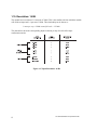
1.8. Digital Word Map: 13 Bit Mode
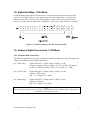
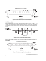
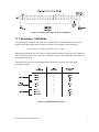
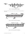
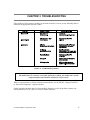
A unipolar analog input signal is translated into a 13-bit plus sign bit digital word. Since the PLC
requires a 16-bit input word, the 13-bit value from the converter is placed into a 16-bit word for
transmittal to the PLC. As shown in the following figure, of the two bits not used for the digital
word, one is used to show the sign of the word and one is used to note values which are “overrange”.
Figure 1.2 13 Bit Word Input to the PLC from the Module
1.9. Analog to Digital Conversions: 13 Bit Mode
1.9.1. Unipolar Mode Conversion
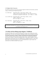
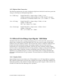
The following equations may be used to calculate the digital word which will result from a particular
voltage or current input in the Unipolar Input Mode:
0 to +5VDC range
Digital Word (WX) = (Input voltage x 32000) ÷ 5 volts
example: to generate an input voltage of 2.5 VDC, the WX value input to
the PLC is calculated as follows: WX = (2.5 x 32000) ÷ 5 = 16000
0 to +10VDC range
Digital Word (WX) = (Input voltage x 32000) ÷ 10 volts
example: 7.5VDC input
WX = (7.5 x 32000) ÷ 10 = 24000
0 to +20mA range
Digital Word (WX) = (Input current x 32000) ÷ 20 mA
example: 10mA input
WX = (10 x 32000) ÷ 20 = 16000
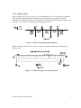
Note:
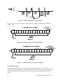
Bit 15 is always returned as a zero, and bit 16 is employed as an over/underrange bit. Consequently,
returned data values change by four.
CTI 2558 Installation and Operation Guide
3