1
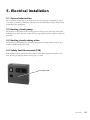
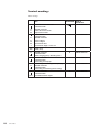
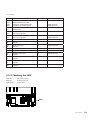
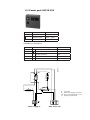
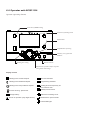
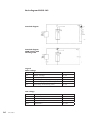
161 505 21-1 2006-01 Installation and maintenance CTC 380 S Model 18 / 22 / 27 / 33 / 40 / 50 / 63 161 505 21-1 2006-01 Installation and maintenance CTC 380 S Model 18 / 22 / 27 / 33 / 40 / 50 / 63 CTC 380 S 3 4 CTC 380 S Table of contents 1. Introduction 1.1 General information..........................................7 2. Important points 2.1 Inportant points ................................................8 2.2 Safety instructions............................................8 2.3 General installation conditions..........................8 3. Technical information 3.1 Technical data...................................................9 3.2 Measurements..................................................10 3.3 Description........................................................11 4. Installation 4.1 General information........................................12 4.2 Transport.........................................................12 4.3 Unpacking.......................................................12 4.4 Boiler stand (accessory kit).............................13 4.5 Boiler room.....................................................13 4.6 Connection to chimney....................................13 4.7 Flue gas temperatures....................................14 4.8 Hydraulic connection boiler.............................14 4.9 Safety valve boiler...........................................14 4.10 Heating circuit pump.....................................14 4.11 Heating circuit mixing valve...........................14 4.12 Connection domestic hot water (DHW).........14 4.13 Drainage/Drain valve....................................14 4.14 Connection water heater..............................14 5. Electrical installation 5.1 General information........................................15 5.2 Heating circuit pump.......................................15 5.3 Heating circuit mixing valve............................15 5.4 Safety limit thermostat (STB)..........................15 5.5 Wiring diagram................................................16 6. Elektrical installation – Comfort-control 6.1 General information........................................17 6.2 Basic unit RVS13.143.....................................17 6.2.1 Terminal markings............................17, 18, 19 6.2.2 Checking the LED........................................19 6.3 Power pack AVS16.290...................................20 6.4 Operator unit AVS37.294..........................21, 22 6.4.1 Selecting heating mode...............................22 6.4.2 Selecting DHW heating mode......................22 6.4.3 Adjusting the room temperature setpoint......23 6.4.4 Displaying information..................................23 6.4.5 Manual control.............................................24 6.4.6 Chimney sweep function.............................24 6.4.7 Commissioning............................................24 6.4.8 Plant diagrams.............................................26 7. Oil burner 7.1 General information....................................... 27 8. Commissioning 8.1 Before commissioning....................................27 8.2 Commissioning...............................................27 8.3 After commissioning........................................27 9. Operation 9.1 General information........................................28 9.2 Regular inspection..........................................28 9.3 Standstill.........................................................28 9.4 Frost risk.........................................................28 9.5 Boiler cleaning................................................29 9.6 Drainage.........................................................29 9.7 Oil operation....................................................29 9.8 Operations disturbance...................................30 9. Declaration of conformity...................................31 CTC 380 S 5 6 CTC 380 S 1. Introduction 1.1 General Information • The CTC 380 S is a 3-stroke oil heating boiler for progressive heating, which really corresponds to the present market demands of low energy consumption, comfort and low environmental influence. The CTC 380 S is designed for firing with a minimum of ecologically harmful emissions and energy losses. The CTC 380 S is available in seven sizes from 18-63 kW. The CTC 380 S supplies the total requirement of heating and DHW of the house. The CTC 380 S has in order to simplify the installation, water- and flue gas connections on the top as well as the rear side of the boiler. The CTC 380 S is equipped with an adapted, extensional weather-compensated Comfort-control which totally fulfils the requirements of a comfortable and energy-saving operation. The CTC 380 S is thanks to the space-generous burner door and easily accessible combustion surfaces very maintenance-friendly. The type indication of the boiler is found on the product label on top of the boiler. CTC 380 S 7 2. Important points Read and take this installation- and operating manual into consideration before the installation and first start of the heating boiler! 2.1 Important points Upon delivery and installation carefully check the following important points: • Unpack the CTC 380 S and check before installation that the product has not been damaged during transport. • Report eventual transport damage to the transporter. • Check in event of that a safety valve is mounted that a safety valve drain pipe to the floor drain is fitted. • Check the condition of the chimney. If necessary, take actions against condensation water. 2.2 Safety instructions The following safety instructions must be observed upon handling, installation and use of the heating boiler: • In a closed system, a non closable safety valve approved according to existing standards must be installed, see the part INSTALLATION. • Ensure that the boiler is currentless before any interventions. • Do not flush the boiler or any of its regulation equipment with water. • The flue gas channel and the ventilation duct of the boiler room for air supply must not be blocked. • Check that the burner and its oil tubes are tight. • The operating switch of the boiler must be off if the oil burner is swung out, for example during cleaning or service. 2.3 General installation conditions A correct function of the CTC 380 S serie, as well as the manufacturer warranty to be valid is only guaranteed when the installation, handling and maintenance are made as by the recommendations in this technical manual. Operation disturbances and defects which are caused by a not workmanlike handling as well as direct violent handling of the product, liberates the manufacturer from its warranty commitments. Please, hand over this technical manual to the customer after the installation! Regulations: The installation of the boiler and the heating system must be carried out by authorized personnel according to existing enigineering standards and building regulations. 8 CTC 380 S 3. Technical information 3.1 Technical data Oil heating boiler CTC 380 S Rated output 18222733 kW 18,32227,333,9 Rated input kW 19,623,729,236,1 Oil supply kg/h 1,652,02,463,05 Flue gas mass flow Boiler resistance g/s 8,2 9,9 12,2 14,7 mbar 0,07 0,10 0,14 0,21 Boiler water resistance (r20K) mbar 2,02,03,03,0 Flue gas losses * % 5,49 5,19 5,61 5,7 Radiation losses * % / W 1,11 / 216 1,11 / 216 0,79 / 215 0,6 / 215 Boiler efficiency * % 93,4 93,7 93,6 93,7 Flue gas temperature * °C 138 136 146 160 Boiler efficiency at 70 °C % 93,8 94 94 94,1 Flue gas temperature at 70 °C °C 130 128 138 152 Max operation pressure boiler Bar 3 3 3 3 Max operation temperature boiler °C 110 110 110 110 l 98,5 98,5 92 92 Water content Weight kg197 197 200,5 210 Number of turbulators St. 6 6 9 9 Turbulator model 21/45 27/45 27/45 21/45 Electrical data 230V 1N~ 230V 1N~ 230V 1N~ 230V 1N~ *) According to EN 303-3 Oil heating boiler CTC 380 S Rated output 405063 kW 39,751,261,6 Rated input kW 42,755,166,9 Oil supply kg/h 3,6 4,65 5,65 g/s 17,1 23,7 29,7 mbar 0,4 0,29 0,5 Flue gas mass flow Boiler resistance Boiler water resistance (r 20K) mbar 5,08,09,0 Flue gas losses * % 5,7 6,75 7,61 Radiation losses * % / W 0,6 / 215 0,45 / 249 0,49 / 329 Boiler efficiency * % 93,7 92,8 91,9 Flue gas temperature * °C 159 160 164 Boiler efficiency at 70 °C % 94,1 93,2 92,3 Flue gas temperature at 70 °C °C 151 152 156 Max operation pressure boiler Bar 3 3 3 Max operation temperature boiler °C 110 110 110 Water content l 927979 Weight kg 210236241 Number of turbulators St. 9 15 15 Turbulator model 27/45 27/45S 27/45S Electrical data 230V 1N~ 230V 1N~ 230V 1N~ *) According to EN 303-3 CTC 380 S 9 3.2 Measurements Legend 1a. Primary flow top R 1”, (18-33)* 1b. Primary flow top R 1 ¼”, (40-63)* 2a. Return flow top R 1”, (18-33)* 2b. Return flow top R 1 ¼”, (40-63)* 3a. Primary flow rear R 1”, (18-33)* 3b. Primary flow rear R 1 ¼”, (40-63)* 4a. Return flow rear R 1”, (18-33)* 4b. Return flow rear R 1 ¼”, (40-63)* 5. Expansion connection R 1” 10 CTC 380 S 6. Drainage R 1” 7a. Flue gas outlet top ” 130 mm, (18-33)* 7b. Flue gas outlet top ” 150 mm, (40-63)* 8. Basic unit Siemens RVS13.143 9a. Operator unit Siemens AVS37.294 9b. Power pack Siemens AVS16.290 10. Adjustable feet M10 11. Flue gas outlet rear *) Output-sizes in kW 3.3 Description The principle parts of the design consist of measure made steel plates. The boiler has been pressure- and tightness tested and is provided with skin-tight heat insulation as well as powder coated cover plates. 1. Flue gas outlet Connections on the top and rear side. 2. Heat insulation In order to minimize the heat losses the boiler is provided with solid, skin-tight heat insulation. 3. Combustion chamber The generous sized combustion chamber offers the adjusted Low NOx oil burner optimal performance. 4. DUO-Temperature System The combustion chamber is surrounded by two mantles, which allows low-temperature operation protected from dew-point corrosion resulting in a long-life operation. 5. Ripples The boiler-sizes 33, 40 and 63 kW are equipped with ripples. The ripples enlarge the the surfaces in which the interchange of heat of the second flue gas stroke takes place. This results in an optimized heat transfer of the flue gases to the boiler water. 6. Turbulators The function of the turbulators is to create turbulence of the flue gases, in order to improve the amount of thermal energy which is transmitted to the boiler water. All sizes are from factory, equipped with for each size adapted standard turbulators. The turbulators are reached behind the cleaning door in the front of the boiler. 7. Cleaning door Thanks to the large cleaning door are the turbulators within easy reach as well as it facilitates the simultaneously cleaning and maintenance of the heating surfaces of the boiler. 8. Hinged arm The cleaning door is equipped with hinges which serves as a hinged arm. In that way is it easier to swing out the burner in connection to inspections and maintenance. 9. Adjustable feet The boiler is equipped with four adjustable feet. 10. Power pack The power pack of the control panel – Siemens AVS16.290. For more information, see the part ELECTRICAL INSTALLATION – COMFORT-CONTROL. 11. Basic unit The basic unit of the Comfort-control – Siemens RVS13.143. For more information, see the part ELECTRICAL INSTALLATION – COMFORT-CONTROL. 12. Operator unit The operator unit of the Comfort-control – Siemens AVS37.294. For more information, see the part ELECTRICAL INSTALLATION – COMFORT-CONTROL. 13. Burner hood The burner hood is an integrated and sophisticated component part of the boiler. CTC 380 S 11 4. Installation 4.1 General information The installation must be carried out by authorized personnel according to existing engineering standards and building regulations. The boiler must be connected to an expansion vessel in an open (the expansion vessel of high placement together with safety- and return pipe) or a closed system. At an open system the distance between the expansion vessel and the highest placed radiator must not be less than 2,5 m to avoid oxygen-enrichment of the system. 4.2 Transport To avoid transport damage, do not unpack the boiler until it has been transported to its site in the boiler room. The boiler can be handled and lifted in the following way: • Forklift • Lift band round the pallet. Note! Only with the packing on. • Sack barrow • By putting carrier pipes in the water connections on the rear side, respectively the build-in 1” carrier sockets on the front side of the boiler Carrier sockets 4.3 Unpacking To avoid damage in the handling, do not unpack the boiler until it has reached its site in the boiler room. After the unpacking check, that the boiler has not been damaged during transport. Report eventual transport damages to the transporter. 12 CTC 380 S 4.4 Boiler stand (Accessory kit) The boiler stand is delivered as accessory kit. The boiler stand contain following parts: 1. Long sides (2x) 2. Short sides (2x) 3. Adjustable feet (4x) (Not in the accessory kit. Use the adjustable feet of the boiler!) 4. M6-Screws (12x) The boiler stand may be assembled according to following items: 1. Screw the long- and short sides together by using M6-Screws (8x). 2. Fasten the adjustable feet on the underside of the boiler stand. 3. Fasten M6-Screws (4x) from below on the upper side of the boiler stand. 4. Place the boiler on the boiler stand by using the M6-Screws in item 3. as guide pins. Do not fasten! 4.5 Boiler room The boiler room must correspond to existing building regulations and particularly then the firing regulations of the present country. The boiler room must be equipped with a venthole for air supply. The cross section area of the venthole must be at least 6,5 cm2 pro 1 kW boiler output. 4.6 Connection to chimney Existing regulations for the design of the chimney must be taken into consideration. An optimal utilization of the flue gases and with that an energy-saving operation, requires hereby a mostly optimized adaption between boiler and burner. The most important conditions are the following: • Good thermal insulation in order to as much as possible avoid temperature losses from the connection between the boiler and chimney. • Accurate sealing of the flue gas connections. • Smooth surfaces of the combustion chamber to avoid turbulence. • Heat-shock resistance as well as water- and steamtight. According to regulations: • The boiler must be connected to the chimney with the shortest feasible flue duct at an angle of 30-45°. • The flue duct must not be fully inserted through the chimney wall. • If flue ducts with a cross-sectional dimension which deviate from the dimension of the flue gas outlet would be used, the connection must be cone-shaped. Cone angle of maximum 7,5°. • By the construction of the flue duct between boiler and chimney must feasible actions be taken to secure that no condensate can flow back to the boiler (condensate trap). CTC 380 S 13 4.7 Flue gas temperatures When a new boiler is being connected to an old chimney, the chimney is often not dimensioned to the new high efficiency of the boiler, which may easily result in condensation in the chimney depending on lower flue gas temperatures. In order to ventilate the chimney with warmer boiler room air, a draught interrupter can be mounted. All boiler-sizes of the CTC 380 Ecoswiss serie has for the current output-size design related operational flue gas temperatures. For flue gas temperature data, see TECHNICAL INFORMATION. 4.8 Hydraulic connection boiler The dimensioning and plumbing of the system shall be accomplished according to the measurements in the part TECHNICAL INFORMATION. 4.9 Safety valve boiler In a closed system, an approved safety valve according to existing regulations must be mounted. The max. Operation pressure of the boiler is 3 bars. The connection pipe between boiler and safety valve must be constructed in such way that no pressure increase is possible. The safety valve drain pipe must be uncovered and visible. Possible exhausting hightemperature hot water must without danger be removed (Caution! Risk of scalding). 4.10 Heating circuit pump A heating circuit pump must be mounted on the primary flow of the boiler. The pump is being supplied with electric current from the boiler. For more information concerning system principles and connections, see ELECTRICAL INSTALLATION – COMFORT-CONTROL. 4.11 Heating circuit mixing valve A heating circuit mixing valve must be mounted on the primary flow of the boiler. The heating circuit mixing valve is being supplied with electric current from the boiler. For more information concerning system principles and connections, see ELECTRICAL INSTALLATION – COMFORT-CONTROL. 4.12 Connection domestic hot water (DHW) Secondary heating circuit The connections located on the rear side of the boiler makes it possible to connect the boiler to a secondary heating circuit. These connections offer also the possibility to connect the boiler to a water heater system. The temperature of the return flow to the boiler must not be lower than 45°C. 4.13 Drainage/Drain valve Shall be mounted on the drainage connection on the rear side of the boiler. 4.14 Connection water heater If the CTC 380 S will be combined together with a water heater, is it of high importance that it’s size and power capacity corresponds to the installed boiler output. The installation must correspond to existing building regulations. Recommended to connect on the rear primary- and return flow of the boiler. For more information concerning system principles and connections, see ELECTRICAL INSTALLATION – COMFORT-CONTROL. 14 CTC 380 S 5. Electrical installation 5.1 General information The installation and wiring of the boiler must be carried out by an authorized electrician and in accordance with valid regulations. The internal boiler wiring is from factory prepared for the installation. 5.2 Heating circuit pump The heating circuit pump for the heating system is being connected to the connection terminal on the basic unit. The switch for the pump is placed on the comfort-control of the boiler. 5.3 Heating circuit mixing valve The heating circuit mixing valve for the heating system is being connected to the connection terminal on the basic unit. 5.4 Safety limit thermostat (STB) If the boiler has been stored extremely cold the safety limit thermostat may have released. Reset by pressing the button on the power section. Reset button STB CTC 380 S 15 5.5 Wiring diagram E-581273 16 CTC 380 S 6.Electrical installation Comfort-control 6.1 General information The CTC 380 S is factory equipped with the Comfort-control Siemens Albatros2. The Comfort-control consists of a basic unit, power pack and operator unit. The power pack and operator unit creates together the control panel of the boiler. Part 6. describes the principal information concerning the Comfort-control. Fore more information concerning functions, programming, system principles etc., please see the Albatros2 Boiler Controllers User Manual. 6.2 Basic unit RVS13.143 6.2.1 Terminal markings CTC 380 S 17 Terminal markings Mains voltage Use L N L1 S3 L1 N T1 T2 S3 4 SK1 SK2 N Q3 N Q2 Y1 N Y2 N QX1 18 CTC 380 S Phase AC 230 V basic unit Protective earth Neutral conductor Phase AC 230 V burner Output burner fault Termininal Type of connector N L AGP4S.05A/109 Phase burner Protective earth Neutral conductor Burner stage 1 Burner stage 2 Input burner fault Input burner stage 1 hours run P AGP8S.07A/109 Safety loop Safety loop Q AGP8S.02E/109 Neutral conductor Protective earth DHW charging pump / diverting valve R AGP8S.03A/109 Neutral conductor Protective earth 1st heating circuit pump S AGP8S.03B/109 1st heating circuit mixing valve opening Neutral conductor Protective earth 1st heating circuit mixing valve closing T AGP8S.04B/109 Neutral conductor Protective earth 1st multifunctional output U AGP8S.03C/109 Low voltage Use Steckplatz Type of connector BSB X60 X50 X30 Service tool OCI700 Radio module AVS71.390 Extension module AVS75.390 Operator unit / boiler control - AVS82.490/109 AVS82.491/109 CL+ CL- BSB data BSB ground B AGP4S.02A/109 CL+ CL- Room unit 2 data Room unit 2 ground B AGP4S.02A/109 CL+ CL- Room unit 1 data Room unit 1 ground B AGP4S.02A/109 AGP4S.03D/109 G+ Room unit power supply 12V B2 M Boiler sensor Ground F AGP4S.02B/109 B3 M DHW sensor top Ground H AGP4S.02C/109 B9 Outdoor sensor M Ground K H1 M Digital-/0..10V input Ground N AGP4S.02F/109 B1 M Flow sensor Ground P AGP4S.02G/109 BX1 M Multifunctional sensor input 1 Ground N AGP4S.02F/109 BX2 M Multifunctional sensor input 2 Ground N AGP4S.02F/109 AGP4S.02D/109 6.2.2 Checking the LED No power supply Ready to operate Local faults LED 2359Z33 LED off: LED on: LED flashes: CTC 380 S 19 6.3 Power pack AVS16.290 Terminal Name L Phase AC 230 V blue Protective earth green + yellow Neutral conductor blue N Verbindung zu Grundgerät Klemme 1 Bezeichnung L 2 Phase AC 230 V basic unit brown Protective earth green + yellow 3 N Neutral conductor blue 4 L1 Phase AC 230 V burner black 5 S3 Input burner fault 3B 1A 4B 2A 2358A16 - S1 1A H1 3B1 1 1 Si C 2 STB 2 PE Si S1 STB H1 L L N Mains supply to N1 L1 S3 1 2 3 4 5 RVS...basic unit Fuse 6,3AT Mains switch with green glow lamp Safety limit thermostat (SLT) 110°C Signal lamp (STB tripped) 6.4 Operator unit AVS37.294 Operator (operating elements Selection of DHW heating Selection of heating mode Information 2359Z62 Confirmation of setting Chimney sweep function STB test Manual control Quitting the setting Adjustment of room Comfort setpoint Navigation and settings Display choices Heating to the Comfort setpoint Info level activated Heating to the Reducted setpoint Programming activated Heating to the frost protection setpoint Process running - please wait Change battery Heating function temporarily off ECO function activ Holiday function active Reference to heating circuit Burner in operation (only oil/gas burner) Maintenance / special mode Fehlermeldungen Display Display showing all availiable segments. 6.4.1 Selecting heating mode Press the button to switch between the different operating modes. The choice made is indicated by a bar which appears below the symbols. Automatic operation Automatic operation controls the room temperature according to the time program. Continous operation or Continous operation maintains the room temperature at the selected operating level. Heating to the Comfort setpoint Heating to the Reduced setpoint Protection When using Protection, the heating system is off. But it remains protected against frost (frost protection temperature), provided there is no power failure. 6.4.2 Selecting DHW heating mode The button is used to switch DHW heating mode on and off. The choice is indicated by a bar which appears below the symbol. DHW mode • On The DHW is heated according to the selected switching program. • Off No DHW heating, the protective function is active. 22 CTC 380 S 6.4.3 Adjusting the room temperature setpoint Turn the setting knob to increase or decrease the Comfort setpoint . For the Reduced setpoint - Press the OK button - Choose operating page ”Heating circuit” and - Adjust the ”Reduced setpoint”. Each time you make a readjustment, wait at least 2 hours, allowing the room temperature to adapt. 6.4.4 Displaying information The button is used to display information. Available information Certain information lines are hidden, depending on the type of unit, unit configuration and operating state. Ausnahmefall Exceptional cases: Error messages If this symbol appears, a plant fault has occured. In this case, press the Info button to obtain more information. Maintenance or special mode If this symbol appears, a maintenance alarm is delivered or the plant has changed to special mode. In this case, press the Info button to obtain more information. CTC 380 S 23 6.4.5 Manual control When manual control is active, the relays are no longer energized and deenergized according to the control state, but are set to a predefined manual operating state depending on their function. The burner relay energized with manual control can be deenergized by the electronic temperature controller (TR). Setpoint adjustment with manual control After manual control has been activated, a change to the basic display must be made. There, the maintenance / special mode symbol appears. Press the Info button to switch to info display ”Manual control” where the setpoint can be adjusted. 6.4.6 Chimney sweep function The chimney sweep function is activated by a short press (maximum 3 seconds) on the chimney sweep button. It produces the operationg state required for making flue gas measurements. SLT-Test The SLT-Test (SLT = safety limit thermostat) is activated by a long press (longer than 3 seconds) on the chimney sweep button. The button must be kept depressed during the entire test. If released, the test will be aborted. The SLT test is shown on the display. The test above must be made by qualified staff since the boiler temperature will be raised above the maximum limit. 6.4.7 Commissioning Prerequisites To commission the units, the following steps must be carried out: • Prerequisite is correct mounting and correct electrical installation and, in the case of wireless systems, correctly working radio links to all the auxiliary units. • Make all plant-specific settings. Special attention must be paid to operationg page ”Configuration”. For that purpose, the relevant operating level is to be selected as follows: Press the OK button on the room unit to switch to programming. Press the Info button for at least 3 seconds and select operating level ”Commissioning” with the setting knob. Then, press the OK button. • Make the functional check as described below • Reset the attenuated outside temperature (operating page ”Diagnostics consumer”, operating line ”Outside temp attenuated” (line 8703). 24 CTC 380 S Functional check To facilitate commissioning and fault tracing, the controller allows output and input tests to be made. With these tests, the controller’s inputs and outputs can be checked. To make the tests, select operationg page ”Input/output test” and go through all available operating lines. Operating state The current operating state can be checked on operating page ”State”. Diagnostics For detailed diagnostics of the plant, check operating pages ”Diagnostics heat source” and ”Diagnostics consumer”.6.4.8 Plant diagrams The application is shown in the form of basic diagrams and extra functions. The basic diagrams can be implemented without using the multifunctional outputs. CTC 380 S 25 Basic diagram RVS13.143 Standard diagram Standard diagram DHW heating with diverting valve Legend Mains voltage Diagram Function Terminals K4 Burner 1st stage T1, T2 Q1 Boiler pump QX1, QX2 Q2 1st heating circuit pump, boiler pump Q2 Q3 DHW charging pump / diverting valve Q3 Y1 1st heating circuit mixing valve Y1, Y2 Low voltage B1 26 CTC 380 S Flow temperature sensor HC1 B1 B2 Boiler temperature sensor TK1 B2 B3 DHW sensor top B3 B9 Outdoor sensor B9 RG1 Room unit 1 CL-, CL+ 7. Oil burner 7.1 General information The CTC 380 S provides optimum combustion conditions for the oil burners available on the market. The commissioning, adjustments and maintenance of the burner must be performed by an authorized heating technician according to the technical manual of the burner. See also the part COMMISSIONING. 8. Commissioning 8.1 Before commissioning Check that: 1. the boiler and heating system are filled with water. 2. all connections are tight and that the chimney connection is made in an correct way. 3. the oil tank is inspected according to existing regulations. 4. the electrical connections are made in an correct way. 8.2 Commissioning 1. Switch on the current with the mains switch. 2. By commisioning applies the Comfort-control the factory pre-set standard values for set points, time program and operating modes. Though is it prerequisited to make settings of the time of the day and date. Further adjustments for personal require- ments are performed according to the technical manual of the Comfort-control. See also the part ELECTRICAL INSTALLATION – COMFORT-CONTROL. 3. Check that the oil burner starts. 4. When the boiler has reached its operating temperature (70-80°C), check and adjust the oil burner in accordance with its technical manual. See also the part OIL BURNER. 8.3 After commissioning Check that: 1. all pipe connections are tight, tighten if necessary. 2. the flue duct is tight and well insulated. 3. the boiler temperature rises upon commisioning. 4. heat goes out to the heating system 5. the heating circuit pump is running and can be controlled from the Comfort-control of the boiler. 6. the tapping points of the house are provided with hot water as the boiler has turned warm. 7. the function of the safety valve is faultless. 8. the boiler and the heating system are well vented. Re-check after a few days. CTC 380 S 27 9. Operation 9.1 General information After the installation check together with the installer that the installation is fully ready for operation. Let the installer show you all important regulation devices, etc. so that you are well aware of how the boiler installation functions and should be maintained. Vent the radiators after appr. 3 days of operation and fill up with more water if necessary. 9.2 Regular inspection The regular inspection should include following items: • • • • • • Check control of the pressure gauge (manometer). By too low pressure, fill-up water in the heating system by means of charging- and drainage device. Check control of the heating oil level in the tank. Check control of the settings of the Comfort-control. Check control of the temperature of the heating boiler, primary flow and flue gas. Check control of the burner according to the instructions in the technical manual from the manufacturer. In a closed system, check control of the safety valve by means of either turning or lifting the regulation device of the valve. Check if water run out from the safety valve drain pipe. 9.3 Standstill If the installation should be put out of operation, use the mains switch. See the part ELECTRICAL INSTALLATION – COMFORT-CONTROL. 9.4 Frost risk Never put the boiler in operation if its pose a risk that the boiler or parts of the heating system is frozen. This leads to damages on the boiler and piping in the house. Consult your heating technician for advice. Concerning protection mode, see the part ELECTRICAL INSTALLATION – COMFORT-CONTROL. 28 CTC 380 S 9.5 Boiler cleaning The boiler must be currentless by the boiler cleaning! The combustion chamber is from the front easily cleaned: • Remove the burner hood. • Switch off the burner. • Pull out the burner Eurostecker. • Undo and remove the burner door screws. The door may now be swinged out without dismantling of the burner. • Remove the turbulators. • Clean the combustion chamber and heating surfaces by using the supplied tube brushes. • Reassemble the turbulators, close the burner door and put back the screws and tighten after finishing the cleaning. • Connect the burner Eurostecker and switch on the burner. • Attach the burner hood. The boiler installation must be regularly cleaned according to existing regulations. 9.6 Drainage The boiler must be currentless upon drainage. The drainage connection/drain valve is low located on the rear side of the boiler. By drainage of the whole system must the heating circuit mixing valve be fully open. In a closed system air must be supplied. 9.7 Oil operation General information: Adjustments and maintenance of the oil burner must always be performed according to the technical manual of the burner. In order to secure that the installation operates correctly, has low energy consumption and minimizes the harmful emissions, is it of great importance that maintenance with a check control in consideration of the setting values is performed on a regularly basis (recommended annual). If you have questions concerning maintenance or any product defaults, please address to your installer. CTC 380 S 29 9.8 Operations disturbance Burner disturbance: • Check if there is oil in the tank. Burner disturbance signal lamp lights: • Check if the oil filter is dirty. Take necessary actions according to instructions in the technical manual of the burner. Boiler disturbance: • The safety limit thermostat has released. Reset by pressing the button on the power pack. See also ELECTRICAL INSTALLATION. Power supply to boiler disconnected: • Check the fuse on the power pack. Check if the mains switch on the power pack is switched on. See also ELECTRICAL INSTALLATION. Unsufficient room heating: • Check the settings of the Comfort-control. See also ELECTRICAL INSTALLATION – COMFORT-CONTROL. Unsufficient DHW: • Check the settings of the Comfort-control. See also ELECTRICAL INSTALLATION – COMFORT-CONTROL. If none of the above mentioned actions corrects the fault, we request you to contact your authorized installer or CTC directly. 30 CTC 380 S CTC 380 S 31


![Deep Time User Manual ver.1.3 [ENG]](http://vs1.manualzilla.com/store/data/005775250_1-8eb61345983a4e3ef84e4b82ef32f1cf-150x150.png)