1
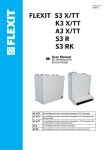
110738E-09
2015-09
Spirit UNI 3
Installation Instructions
Air Handling Unit & Automatic Control
UNI 3 Installation Instructions
Content
1
Planning and preparation work
1.1 Joiner / fitter
1.2 Plumber (if the unit has a water battery)
1.3 Electrician
2 Wall mounting
2.1 Location requirements
2.2 Space required
2.3 Duct locations
3 Floor mounting
3.1 Location requirements
3.2 Space required
3.3 Installation
4 Duct Connection
4.1 Duct connection in the base
4.2 Connecting the unit
5 Electrical work
5.1 Temperature sensor for heating (B1) (if the unit has a water battery)
5.2 Frost sensor for water battery (B5) (if the the unit has a water battery)
5.3 Outdoor air damper (if the unit has a water battery)
6 Plumbing work*
7 Encasing
7.1 Preparations
7.2 Flexit duct cover
8 Installation of control panel CI 60/600
8.1 Content
8.2 Installation of CI60/600
8.3 Concealed installation
8.4 Surface installation
8.5 Finishing off – CI60
8.6 Finishing off – CI600
9 Adjusting the unit
9.1 Adjustment with CI60
9.2 Adjustment with CI600
9.2.2 Temperature regulation
10 Installation of external kitchen hood
10.1 Kitchen hoods without a motor
10.2 Kitchen hoods with a motor
11 Adjusting the kitchen hood
11.1 Kitchen hoods without a motor
11.2 Kitchen hoods with a motor
12 General drawings and system drawings
12.1 System drawing (with heating element)
12.2 System drawing (without heating element)
12.3 General picture (with heating element)
12.4 General picture (without heating element)
12.5 Duct location
13 Technical data
14 Physical dimensions
15 Capacity and sound data
15.1 Supply air side
15.2 Extract air side
16 Temperature efficiency (according to EN 308)
17 Final checks / Starting
17.1 Final checks
17.2 Starting
18 CE Declaration of Conformity
Our products are subject to continuous development and we therefore reserve the right to make changes.
We also disclaim liability for any printing errors that may occur.
2
4
4
4
4
5
5
6
7
10
10
10
10
12
12
12
13
13
13
13
13
14
14
14
15
15
15
16
16
16
16
17
17
18
18
19
19
19
19
19
19
20
20
20
21
21
22
22
23
24
24
24
25
26
26
26
26
UNI 3 Installation Instructions
!
Important Safety Instructions:
It is the installer’s responsibility to carry out a full safety and function assessment of the appliance.
To reduce the risk of fire, electric shock or injury, read all the safety instructions and warning texts before using the unit.
•
•
•
•
•
•
•
This unit is only designed to handle ventilation air in housings and commercial buildings
It must not be used to extract combustible or flammable gases
Remove the power plug before commencing any service and maintenance work
Before you open the door, the unit must be dead and the fans must have been given time to stop (min. 3 minutes)
The unit contains heating elements that must not be touched when they are hot
The unit must not be operated without the filters being in place
Tumble driers should not be connected to the unit
To maintain a good indoor climate, comply with regulations and, to avoid condensation damage, the unit must never be
stopped apart from during service/maintenance or in connection with an accident.
Symbols Used
These products have a number of symbols that are used
to label the product itself and in the installation and user
documentation.
Supply air
Extract air
Kitchen air
DANGER! ELECTRICITY
DANGER! DO NOT
TOUCH
!
Exhaust air
CAUTION! When a text bears this symbol, it
means that personal injury or serious damage to
the equipment may result if the instructions are
not followed.
Outdoor air
NB! When a text bears this symbol, damage to
equipment or poor efficiency may be the consequence of not following the instructions.
This appliance can be used by children aged from 8 years and above and
persons with reduced physical, sensory or mental capabilities or lack of
experience and knowledge if they have been given supervision or instruction
concerning use of the appliance in a safe way and understand the hazards
involved. Note that the product is not intended for use by children.
Children shall not play with the appliance. Cleaning and user maintenance
shall not be made by children without supervision.
EXAMPLE OF NIPPLE LOCATION
(shown as a right-hand model)
Our products are subject to continuous development and we therefore
reserve the right to make changes.
We also disclaim liability for any printing errors that may occur.
3
UNI 3 Installation Instructions
1
Planning and preparation work
1.1
Joiner / fitter
1.2
Door gaps
Check that the air moves from rooms with supply air valves
to rooms with extract air valves.
Plumber (if the unit has a water battery)
Water pipe layout and placement of the water battery
(channel battery) must be planned. These must be kept
warm to avoid frost damage. See separate instructions that
accompany the water battery.
Kitchen
If the kitchen ventilator is designed with a motor, suitabl supply air must be ensured. See chapters 9 and 10 for details.
Fireplace
When using the fireplace suitable supply air must be ensured.
!
1.3
The water battery must be located in a room
with a drain.
Electrician
Power supply
The units have an approx. 2.5 m cable with plug and require a
single-phase earthed socket nearby. Plug requirements: 10 A.
It is important for the plug to be accessible for servicing
when the unit is fully installed.
Installation in the building
The unit should not be placed near rooms that are sensitive
to noise. When placing by an inner wall, an isolated wall with
cut off studs and cut off boards, as well as double plaster
board, is recommended. Cabinet units in wet rooms should
be placed outside zone 2.
If a separate kitchen hood is used, it must have its own
socket (10A) in the area above the cabinet. If the kitchen
hood is going to be connected to the ventilation unit, a
minimum Ø16 conduit must be installed for the three-core
signal cable. NB!
Positioning must accord with individual
countries' electrical safety legislation. Check
which rules apply in your country.
Suspension of cabinet unit
Suitable transoms between studs minimum (48 x 98 mm) are
required for the screws.
Access
The unit must have good access for service/maintenance.
See chapters 2 and 3 for details.
Fire requirements
Any fire safety requirements must be clarified.
The power cable grommet must be fastened with a torque
of 2.0Nm.
Wiring for control switches
Pipe Ø 20 for pulling of ISDN cable for control of the unit,
laid between the unit and an easily accessible place in the
property (e.g. outside the bathroom) and ending with a
simple flush-mounted double wall box. The control switches
are placed here. The control wire must be placed min. 30 cm
away from cables carrying mains voltage or higher.
Control panel
The control panel is adapted for concealed installation over
a single connection box, or surface installation on the wall.
Duct cover
Plan and calculate the placement of the unit and duct cover
carefully before you start. See chapters 7 for details.
!
Placement of heat sources must be coordinated with
extraction valves, so that heat is not sucked straight out
through the valves or door gaps.
4
CAUTION! Each product’s installation
instructions must be followed.
UNI 3 Installation Instructions
2
Wall mounting
2.1
Location requirements
Fig. 1
LIVING ROOM
The unit is designed to be installed in boiler rooms, laundry
rooms, stores or other suitable areas.
Positioning must accord with individual
countries' electrical safety legislation. Check
which rules apply in your country.
The unit should be placed by a wall that has no room on
the other side that is sensitive to noise. The wall should be
soundproofed with, for example, rock wool, to reduce the
transfer of sound. Double plasterboard in the wall, cut off
studs and cut off plasterboard is recommended (see Fig. 1).
TECHNICAL ROOM
If the unit is placed in spaces with high humidity (bathroom
etc), condensation might occur on the surface of the unit
when outdoor temperatures are very low.
appropriate
isolation
The base should be stable and level.
LIVING ROOM
TECHNICAL ROOM
5
UNI 3 Installation Instructions
2.2 Space required
The unit must be installed with space for servicing and
maintenance such as filter replacement and cleaning of
fans and rotary wheel-type heat exchanger (see Fig. 2). The
control cable with plug for automatic operation on top of the
unit must be easily accessible.
These are minimum requirements and only take
service needs into account.
Positioning must accord with individual
countries' electrical safety legislation. Check
which rules apply in your country.
Fig. 2
200mm (minimum)
400mm (cover)
5mm
5mm
ROTOR
484mm
520mm
8mm
6
500mm
520mm (with door)
700mm
980mm
720mm
UNI 3 Installation Instructions
2.3 Duct locations
The unit is available in left and right versions (exhaust air
duct to the left or right), depending on what is the most
favourable duct location.
The duct connections for outdoor air can be moved to the
bottom of the unit if desired, by exchanging the ducts and
covers.
See chapter 4 and chapter 11.5 for information about moving
ducts, as well as duct placement in the bottom and top of left
and right models respectively.
Alternative wall mounting methods:
1. Horizontal installation (Fig. 3)
2. Sideways installation (Fig. 4)
Fig. 4
Fig. 3
7
UNI 3 Installation Instructions
The enclosed wall brackets are used for wall mounting. The
same mounting is used whether the unit is installed with
ducts up or out to the side (see Fig. 5).
Fig. 6
CEILING
• The wall bracket (Fig. 6) is screwed to the wall using the
enclosed screws.
• The unit is suspended from the rail (Fig. 7). Hold the unit
at an angle when hooking it onto the wall.
The upper edge of the wall bracket should be mounted
65 mm higher than the top of the unit. If one desires, for
example, that the top of the unit shall be 400 mm under the
ceiling, the wall bracket should be mounted 335 mm from
the ceiling, measured from the ceiling and down to the upper
edge of the wall bracket.
335 mm
Fig. 5
horizontal installation
Fig. 7
sideways installation
8
UNI 3 Installation Instructions
Fig. 8
NB! When the unit is hung sideways the door
must be secured with two end studs and a strap.
The end studs are screwed on with the enclosed screws when
the door is closed (see Fig. 8 and 9).
The strap is attached to the inside of the door and the inside
of the unit (see Fig. 10). There are attachment points both in
the left and right ends of the unit. Use the attachment points
that are uppermost when the unit is hung on the wall. This will
prevent the strap from catching in the door when it is closed.
Fig. 9
Fig. 10
9
UNI 3 Installation Instructions
3
Floor mounting
3.1
Location requirements
3.2 Space required
The unit is designed to be installed in boiler rooms, laundry
rooms, stores or other suitable areas.
The unit must be installed with suitable space for servicing
and maintenance such as filter replacement and cleaning
of fans and recovery system (see Fig. 12). Control cable with
plug for automatic control must be easily accessible.
Positioning must accord with individual
countries' electrical safety legislation. Check
which rules apply in your country.
These are minimum requirements and only take
service needs into account.
When installing on the floor, in consideration of noise and
vibrations, absorption feet should be used (see Fig. 11).
Flexit offer absorption feet as accessories (art.no. 110955).
The unit should be placed so that there is no danger of
bothersome noise in nearby rooms. It is especially important
that the unit is not placed directly over bedrooms.
3.3 Installation
The unit is available in left and right versions (exhaust air
duct to the left or right), depending on what is the most
favourable duct location.
The duct connections for outdoor air can be moved to the
bottom of the unit if desired, by exchanging the ducts and
covers.
If the unit is placed in spaces with high humidity (bathroom
etc), condensation might occur on the surface of the unit
when outdoor temperatures are very low.
See chapter 4 and chapter 12.3 for information about
moving ducts, as well as duct placement in the bottom and
top of left and right models respectively.
The base should be stable and level.
Fig. 12
980mm
500mm
Fig. 11
ROTOR
520mm (with door)
100mm
400mm
5mm
absorption feet
10
720mm
5mm
UNI 3 Installation Instructions
Fig. 13
NB! The door of the unit is too heavy to hold
itself closed when the unit is on the floor. It must
therefore be secured with two end studs and a
strap.
The end studs are screwed on with the enclosed screws when
the door is closed (see Fig. 13 and 14).
The strap is attached to the inside of the door and the inside
of the unit (see Fig. 15). This can be attached to either the
left or right side.
Fig. 14
Fig. 15
11
UNI 3 Installation Instructions
4
Duct Connection
Fig. 16
4.1 Duct connection in the base
3
The duct connections for outdoor air can be moved to the
bottom of the unit if desired, by exchanging the ducts and
covers. To loosen the insulation and ducts, do the following
(see Fig. 16):
1. Turn the duct insulation (polystyrene) a quarter turn so that
the marks in the insulation and in the top of the unit are
directly over each other, and then lift up the insulation.
2. Unscrew the fastening screws which sit in the plastic duct.
3. Screw off the plastic duct.
1
2
When installing the ducts, follow the same procedure in reverse
order. Install the sealing ends in the bottom of the ducts which
will be used.
4.2 Connecting the unit
•
•
•
•
•
•
•
•
•
See Fig. 17.
Ensure that the ducts arrive at the right duct - see the
markings on the unit (top and behind the door), as well as
Indicators
chapter 12.5.
Pull the duct insulation well up to the unit.
To avoid the formation of condensation, it is particularly
important for the outdoor and exhaust air ducts to have
insulation and a plastic sleeve pulled right down to the
unit. Seal the plastic sleeve to the unit with ties.
All ducts that pass through a cold zone must be insulated.
The ducts normally require min. 50 mm insulation with
an insulation capacity equivalent to λ = 0.035 W/m.°C or
Fig. 17
better.
The planner is responsible for ensuring that the necessary
correct insulation and steamtight sleeve are used in
relation to the location/temperature requirements.
Lay the outdoor air duct with a slight incline towards the
outdoor air cap so that any water that enters drains out
again.
The ducts should be soundproofed properly, especially
above the ventilation unit.
3
Pull the duct well over the seal on
the nipple.
The duct insulation is guided
right down to the polystyrene
around the duct. It is very
important that there is no slip
between the duct insulation and
the polystyrene where this may
lead to condensation and/or the
formation of ice.
The plastic sleeve is
pulled right down to
the unit. Fasten the
sleeve with ties.
12
UNI 3 Installation Instructions
5
Electrical work
!
5.2 Frost sensor for water battery (B5) (if
the the unit has a water battery)
CAUTION! The unit should be installed with an
earth fault breaker. All electrical connections
must be installed by qualified electricians.
To avoid frost in the battery a water battery sensor (B5)
must be installed in the water battery pipe where the cold
water leaves the battery.
Positioning must accord with individual
countries' electrical safety legislation. Check
which rules apply in your country.
See wiring diagram enclosed with the unit.
5.3 Outdoor air damper (if the unit has a
water battery)
NB! Ensure that the plug for the unit is not
boxed in.
To avoid frost damage to the water battery during
downtime/loss of power, a closing air damper must be
installed on the outdoor air duct. The damper motor must
have a spring so that it closes when power is stopped.
The unit is supplied with a 2.5 m cable with plug.
The cable comes out of the top of the unit and is connected to
a 230 V 50 Hz single-phase earthed power point that is placed
in an easily accessible position close by. The power plug shall
be used as the service switch. See chapter 12 for fuse sizes.
6 Plumbing work*
*If the unit shall have heating with water battery.
The control panel is adapted for concealed installation over
a single connection box, or surface installation on the wall.
All plumbing work must be performed by an authorised
plumber. Place the unit close to a gully to avoid damage
caused by any water leaks.
The unit has a low-voltage cable (with joint) that is intended for
the control panel. It is important that this plug is easily accessible
afterwards for possible faults, or when changing the unit.
NB! The low-voltage cable must be laid a
minimum of 30 cm from cables carrying mains
voltage or higher, and shall be pulled through
20 mm conduit pipe when installed. The cable
length must not exceed 24 meters.
The low-voltage cable is enclosed in the control panel
packaging.
You’ll find the control panel in a box in the ventilation unit
packaging. The low-voltage cable must be laid between the
unit and the switch unit. See chapter 15 about automatic
control.
NB! Temperature sensor B1 must be positioned
after the water battery.
5.1
Temperature sensor for heating (B1) (if the
unit has a water battery)
This shall be placed in the supply air duct (red on Flexit
drawing/Symbol use page 3) approx. 1 m from the water
battery. Roll out the marked coil of cable on the unit near
the supply air duct. Drill a Ø 7 mm hole in the duct where the
sensor can be inserted. Tighten the hole with acrylic sealant
and tape the cable in place on the outside of the duct so
that it stays in place.
See wiring diagram enclosed with the unit.
13
UNI 3 Installation Instructions
7
Encasing
7.1
NB! For service reasons the casing must have
an opening or a removable front.
Preparations
The placement of the cover is naturally affected by the
placement of the unit. Therefore plan the placement of both
the unit and the cover prior to installation.
NB! To prevent transferring noise and vibrations
from air handling unit, the cover should not be in
direct contact with the unit.
The radiated noise from the unit specified in the sound data
does not include possible noise from ducting. The cover
should therefore be soundproofed too.
7.2 Flexit duct cover
The Flexit duct cover is available as an accessory (see Fig.
18).
Fig. 18
14
UNI 3 Installation Instructions
8 Installation of control panel CI 60/600
8.1 Content
ontent
4
Fig. 19
1
2
3
5
1.
2.
3.
4.
5.
Control panel
Back piece for concealed installation
Back piece for surface installation
Installation instructions
Cable for control panel
8.2 Installation of CI60/600
Fig. 20
!
CAUTION! The control panel must be connected to the ventilation unit before the ventilation
unit is connected to mains.
Lay the cable for the control panel between the ventilation
unit and the control panel. The control panel is adapted for
concealed installation over a single connection box (use low
back piece, item no. 2) or surface installation on the wall (use
high back piece, item no. 3).
Click the cable into the contact at the back of the control
panel and into the contact on the top of the ventilation unit.
OBS! The low-voltage cable must be at least
30 cm from cables carrying mains voltage or
higher. With concealed installation, the cable is
laid in 20 mm conduit pipes. The cable length must not
exceed 24 meters.
ON
OFF
Configuration
Setting
It is possible to connect two CI60 panels and one CI600
panel to each unit. If several CI60 panels are used, each
panel must have its own identity. This is selected with the
switch on the panel’s printed circuit board (se Fig. 20). Use
the appropriate table settings. The panels can be connected
serially, in arbitrary order.
CI 600 (MASTER)
Automatic
CI60 1 (SLAVE)
OFF
CI60 2 (SLAVE)
ON
CI60 1 (MASTER)
OFF
CI60 2 (SLAVE)
ON
CI 600 (MASTER)
Automatic
OFF = MASTER
ON = SLAVE
CI60 (SLAVE)
Irrelevant
15
UNI 3 Installation Instructions
8.3 Concealed installation
8.5 Finishing off – CI60
Lay the cable between the wall box and the ventilation unit in
the preinstalled conduit pipe. Fit the back piece (item no. 2),
over the wall box and click the cable in directly from behind
as in the illustration (se Fig. 21).
Slide the panel off as shown by arrow no. 1 (see Fig. 23) and
fit the control panel straight into the back piece as shown
by arrow no. 2 (see Fig. 24) until it clicks into place. Slide the
panel back on.
Fig. 21
Fig. 23
Fig. 24
1
2
8.4 Surface installation
8.6 Finishing off – CI600
Lay the cable between the back piece (item no. 3), and the
ventilation unit. Cut out the perforation in the corner of the
back piece that is suitable for installation. Screw the back
piece to the wall with suitable screws. Click the cable into
the control panel from below, where there is a socket in the
printed circuit board (se Fig. 22).
Fit the control panel over the hooks in the back piece as
shown by arrow no. 1 and then click the panel into place at
the bottom edge as shown by arrow no. 2 (see Fig. 25).
Fig. 25
Fig. 22
2
16
1
UNI 3 Installation Instructions
9 Adjusting the unit
9.1 Adjustment with CI60
Fig. 26
The unit's air supply MUST be adjusted before
the unit is used for the first time. This should
be done in accordance with the projection
documents. Adjust the values based on the projected
values.
9.1.1 Adjustment
9
8
10
11
Only stage 2 (NORMAL) needs to be adjusted. Stages 1
and 3 have fixed settings, while stage 2 has to be adjusted as
required in the individual home.
The function of the different stages:
MIN
Must not be used when the home is in use.
Must not be used in the first two heating
seasons.
NORMAL
Used under normal conditions. On this
setting the air supply must be adjusted
according to current regulations.
MAX
Used if there is a need for increased air
supply on account of higher occupancy or
a raised humidity level, for example during
showering or when clothes are being dried.
This setting is normally used for limited
periods.
The ventilation unit's air supply is adjusted in speed level
NORMAL using the knobs on the back of the cover. Knob 9 is
used for supply air level and knob 8 for extract air level (see
Fig. 26). The adjustment range is 20-100% of the maximum
level according to the scale on the knob.
Factory settings for supply air/extract air:
MIN
50% (fixed)
NORMAL
75% (variable)
MAX
100% (fixed)
9.1.2. Adjusting the temperature
The temperature required for the supply air can be set
with knob 11. The adjustment range is 10 - 30°C. It should
normally be set to around 18°C. Use of the factory setting is
recommended.
If necessary, the ventilation unit's additional heating can
also be switched ON/OFF with switch 10. In this case only
the rotating heat exchanger is used as a source of heat. It is
best to leave it in ON position, as the unit will then respond
automatically when there is a need for additional heating.
17
UNI 3 Installation Instructions
9.2 Adjustment with CI600
This dialog is identical for the supply air and extract air fans.
The fans are adjusted individually to the desired capacity for
the respective speed.
The unit's air supply MUST be adjusted before
the unit is used for the first time. This should
be done in accordance with the projection
documents. Adjust the values based on the projected
values.
SUPPLY AIR
MIN SPEED
NORMAL SPEED
MAX SPEED
9.2.1 Adjustment
Only stage 2 (NORMAL) needs to be adjusted.
50% OK?
75%
100%
Note that it is also possible to adjusted stages 1 and 3
with a CI600 control panel. This should only be done if a
special need arises, however. This is because it is extremely
important to have adequate air flow rates.
The function of the different stages:
MIN
Factory settings for supply air/extract air:
Must not be used when the home is in use. Must
not be used in the first two heating seasons.
NORMAL Used under normal conditions. On this setting
the air supply must be adjusted according to
current regulations.
MAX
MIN
50% (variable)
NORMAL
75% (variable)
MAX
100% (variable)
9.2.2 Temperature regulation
Used if there is a need for increased air supply
on account of higher occupancy or a raised
humidity level, for example during showering
or when clothes are being dried. This setting is
normally used for limited periods.
In this menu screen (located under "Advanced user") you
configure the temperature regulation and cooling functions.
TEMPERATURE REGULATION
REGULATION TYPE
COOLING
NEUTRAL ZONE
EXT. TEMP. CONTROL
First go to the "Advanced user" menu, enter the PIN and
press OK:
>
>
OK?
>
PIN CODE
1 0 0 0
OK?
Regulation type
If supply air regulation is selected, no further settings can
be set here. If extract air regulation is selected, the max. and
min. supply air temperatures can also be specified.
Then go to the "Fan control" menu. The fans are selected and
configured in this menu screen. Then go to adjustment of
the extract air fan and supply air fan.
FAN REGULATION
SUPPLY AIR
EXTRACT AIR
TIMER
AIR VOLUME COMP
>
>
>
OK?
18
REGULATION TYPE
REGULATION
MAX SUPPLY AIR TEMP
MIN SUPPLY AIR TEMP
EXTR OK?
35°
15°
UNI 3 Installation Instructions
10 Installation of external kitchen
hood
If you use an external kitchen hood, follow the
documentation regarding installation and adjusting air flow
rates which is supplied with the hood.
10.1 Kitchen hoods without a motor
(connected to unit)
The ventilation unit has a separate connection point for
kitchen hoods without a motor. Between the unit and the
hood an electrical cable (low-voltage) must be connected
in order to force the air flow in the hood via the switch on the
hood.
10.2 Kitchen hoods with a motor
(not connected to unit)
A kitchen hood with a motor is not installed to the unit. This
has its own duct system for air evacuation.
With the kitchen hood it is possible to compensate for the
amount of air drawn out of the house.
See chapter 10.2 for more information.
11 Adjusting the kitchen hood
If the hood is not supplied by Flexit, the supplier of the
kitchen hood must plan air flow rates both for extraction and
in the hood, and arrange for supply air to the hood.
11.1 Kitchen hoods without a motor
(connected to unit)
The air flow rate over the hood is regulated according to
the planned air flow rate. Flexit’s kitchen hoods handle
odour absorption up to 150 m³/h. It is not necessary to
compensate for the supply air fan to achieve a balanced air
flow rate.
11.2 Kitchen hoods with a motor
(not connected to unit)
When using a kitchen hood with a motor, the extract air flow
rate will increase. To compensate for this, the ventilation unit
can be set give a higher supply air flow rate than extract air
flow rate.
A signal to the unit is required when the kitchen hood is used:
1. external switch with OFF/ON signal on the circuit board to
the unit (SP4-G0, see the circuit diagram).
2. Install the pressure relay (accessory).
It works like this:
The supply air fan will be increased to the maximum stage,
while the extract air fan will continue at the MIN-stage in
order to compensate for the volume of air the cooker hood
evacuates from the building. This is important to balance the
ventilation in the building.
Check the kitchen hood’s maximum air capacity (using
the enclosed capacity diagram) against the maximum
capacity of the air supply fan. If the kitchen hood has a
higher capacity than the unit’s supply air fan, the unit will
not manage to compensate for the loss of air, and sufficient
supply air must be arranged in some other way.
19
UNI 3 Installation Instructions
Fig. 27
12 General drawings and system
drawings
Exhaust
air
Outdoor
air
Extract
air
Supply
air
12.1 System drawing (with heating element)
(left model)
B1
Temperature sensor, supply air
B4
Temperature sensor, outdoor air
EB1 Heating element
F10 Overheating thermostat, manual reset
F20 Overheating thermostat, automatic reset
FI1
Supply air filter
FI2
Extract air filter
M1
Supply air fan
M2 Extract air fan
HR-R Heat recovery system
M4 Rotor motor
K
Kitchen hood
B4
M2
B1
EB1
FI1
F20
FI2
F10
M1
HR-R
M4
K
UNI 3 User Manual
Fig. 28
12.2 System drawing (without heating element)
(left model)
B1
Temperature sensor, supply air
B4
Temperature sensor, outdoor air
FI1
Supply air filter
FI2
Extract air filter
M1
Supply air fan
M2 Extract air fan
HR-R Heat recovery system
M4 Rotor motor
K
Kitchen hood
Exhaust
air
Outdoor
air
Supply
air
Extract
air
B1
B4
M2
M1
FI1
HR-R
K
M4
20
FI2
UNI 3 Installation Instructions
Fig. 29
11
5
12.3 General picture (with heating element)
(left model)
1 (FI2)
Extract air filter F 7
2 (FI1)
Supply air filter F 7
3 (EB1)
Heating element
4 (F10-20) Heating overheating thermostat (Reset)
5 (F10-20) Heating overheating thermostat (Reset)
6 (M1)
Supply air fan
7 (M2) Extract air fan
8 (HR-R) Heating recovery system
9 (M4)
Rotor motor
10
Control unit
11
Connection for external kitchen hood
12
Temperature sensor, supply air
13
Temperature sensor, outdoor air
13
12
10
3
4
9
2
1
7
6
8
12.4 General picture (without heating element)
Fig. 30
8
(left model)
1 (FI2)
Extract air filter F 7
2 (FI1)
Supply air filter F 7
3 (M1)
Supply air fan
4 (M2)
5 (HR-R)
Extract air fan
Heating recovery system
6 (M4)
Rotor motor
7
Control unit
8
Connection for external kitchen hood
9
Temperature sensor, supply air
10
Temperature sensor, outdoor air
10
9
7
6
2
1
4
3
5
21
UNI 3 Installation Instructions
12.5 Duct location
13 Technical data
Fig. 31
Kitchen air
Left model top
Left model bottom
UNI 3 RE
UNI 3 R
Rated voltage
230v 50Hz
230v 50Hz
Fuse
10A
10A
Rated current, total
6,16 A
1,4 A
Rated power, total
1416 W
216 W
Rated power, electric battery
1200W
Rated power, fans
2x10⁶W
Rated preheating power
-
-
Fan type
B-wheel
B-wheel
Fan motor control
0-10V
0-10V
Fan speed - max. rpm
3390 rpm
3390 rpm
Automatic control standard
CU60
CU60
Filter type
F7
F7
Filter dimensions (BxHxD)
419x192x31
mm
419x192x31
mm
Weight
67kg
67kg
Duct connection
Ø160mm*
Ø160mm*
Height
700mm
700mm
Width
720mm
720mm
Depth
520mm
520mm
*Kitchen connection Ø125mm
Kitchen air
Right model top
Right model bottom
22
2x10⁶W
UNI 3 Installation Instructions
14 Physical dimensions
Fig. 32
700mm
720mm
484mm
520mm
520mm
Ø=125mm
Ø=160mm
23
360mm
244mm
190mm
244mm
120mm
116mm
UNI 3 Installation Instructions
15 Capacity and sound data
15.1 Supply air side 0
20
Air flow rate [l/s]
40
60
80
100
Yellow field:
SFP < 1.0 per fan
SFP < 1,0
Fig. 33
100
100%
80
400
80%
300
100%
200
80%
100
60%
60
80dB (A)
60%
40%
40
20
75dB (A)
40%
60dB (A)
0
65dB (A)
Power consumption [W]
Contact resistance [Pa]
500
70dB (A)
0
Air flow rate [m³/h]
0
100
200
300
400
Luftmængd
15.2 Extract air side
Air flow rate [l/s]
0
20
40
600
60
80
100
SFP < 1,0
100%
400
80
80%
300
100%
200
80%
100
60%
60
60%
69dB (A)
40%
65dB (A)
60dB (A)
55dB (A)
50dB (A)
40%
0
40
Power
consumption
Effektforbruk
[W] [W]
100
500
Contact resistance [Pa]
Yellow field:
SFP < 1.0 per fan
20
0
Air flow rate [m³/h]
0
100
200
300
24
400
Explanation of the diagrams
Sound data is specified as sound effect
level LwA in the capacity diagrams (this
is sound to the duct).
These values can be corrected using
the table for the various octave bands
if you want to look at Lw (without adaptation to A-band).
The correction table for the respective
octaves is specified in Lw, which means that,
after conversion per octave for the respective supply air and extract air, you get these
values in Lw.
Radiated sound from the unit must be calculated on the basis of the supply air diagram.
Correction factor for Lw
Hz
63
Lw(dB)
125
Lw(dB)
250
Lw(dB)
500
1000
2000
Lw(dB) Lw(dB) Lw(dB)
4000
Lw(dB)
8000
Lw(dB)
Supply air
1
-1
3
-1
-7
-11
-20
-36
Extract air
2
0
1
2
-16
-21
-32
-52
Radiated
-50
-46
-33
-39
-50
-53
-60
-70
LwA
(dBA)
-38,6
> EXAMPLE 1
> EXAMPLE 2
> EXAMPLE 3
Sound to the duct in the
respective octaves is specified in Lw.
Radiated sound in Lw per
octave.
Total radiated sound from the unit in LwA.
The operating point gives
70 dBA from the capacity
diagram for supply air. I am
interested in what this is
specifically in the 500 Hz
range.
70 dBA -1 = 69 dB, which is
then an Lw value (sound effect level without adaptation
to the ear’s A-band)
At the bottom of the table, a total value is
specified for radiated sound from the unit
in LwA. This is an aggregate value and is the
total of the radiated values in Lw for the various octaves. It has then been corrected for
A-band.
If, at the working point, you
read off 70 dBA in the supply
air capacity diagram (which
specifies sound to the duct)
to then get an Lw value in the
respective octaves, you deduct
the value in the current octave
for the row with radiated sound.
This is used as follows:
You read off the LwA value in the supply air
capacity diagram, in our example 70 dBA,
and then deduct the total value (also an LwA
value).
LwA 70 dBA – 38.6 dBA = 31.4 dBA (which is
then specified in LwA sound effect level adapted to the ear’s A-band).
70 dBA – 39 (for 500 Hz) = 31
dB, which is then an Lw value
and specifies radiated sound
from the unit in this octave.
16 Temperature efficiency (according to EN 308)
[l/s]
60
70
80
90
100
80
60
%
40
20
0
200
85 % @ 330 m³/h
250
300
[m³/h]
25
350
UNI 3 Installation Instructions
17 Final checks / Starting
18 CE Declaration of Conformity
17.1 Final checks
This declaration confirms that the products meet the
requirements in the following Council Directives and
standards:
2004/108/EC Electromagnetic compatibility (EMC)
2006/95/EC Low-voltage Directive (LVD)
2006/42/EC Machine Directive (Safety)
Check the following points:
Description
Chapter
Performed
The duct insulation is performed in
accordance with the manual and the
technical documents
4
The ducts are connected to the correct
ducts
4
Adjustment has been carried out
in accordance with the manual and
projection documents
8
The unit operates normally at all stages
-
Safety standard:
EN 60335-1:2012 + A11
The rotor rotates freely
-
EMF standard:
EN 62233: 2008
The rotor rotates with heat required
-
EMC standard:
Heating switches in
-
The unit has filters both for outdoor air
and extract air
-
EN 55014-1.2006 + A1 + A2
EN 61000-3-2: 2006 + A1 + A2
EN 61000-3-3: 2013
EN 55014-2:1997 + A1 + A2
Producer:
FLEXIT AS, Televeien 15, 1870 Ørje
Type:
UNI 3 R
Ventilation unit
Complies with the following standards:
The product is CE-marked: 2010
17.2 Starting
•
•
•
•
Check that the control panel is connected.
Connect the mains plug to the unit.
The unit will now start.
The unit will automatically carry out a start up procedure
of approx. 1 min.
• After the start up procedure the unit will follow the settings that are set up in the control panel.
• Changes in settings are made from the control panel.
• Adjustments have been made in accordance with the
manual and project planning documents (documentation
of ventilation data).
FLEXIT AS 26.08.2010
Frank Petersen
Adm. dir.
The right to give notice of lack of conformity applies to this product in
accordance with the existing terms of sale, provided that the product is
correctly used and maintained. Filters are consumables.
The symbol on the product shows that this product must not be
treated as household waste. It must be taken to a reception station
for recycling of electrical and electronic equipment.
By ensuring correct disposal of the equipment, you will contribute
to preventing negative consequences for the environment and
health that incorrect handling may entail. For further information on
the recycling of this product, please contact your local authority, your refuse
collection company or the company from which you purchased it.
Notice of lack of conformity as a result of incorrect or defective installation must
be submitted to the installation company responsible. The right to give notice of
lack of conformity may lapse if the system is used incorrectly or maintenance is
grossly neglected.
26
27
Flexit AS, Televeien 15, N-1870 Ørje www.flexit.no