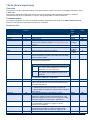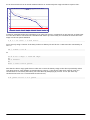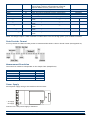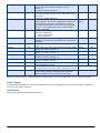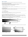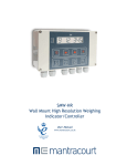
1
T24 Technical Manual
Programming guide & advanced
documentation
User Manual
www.mantracourt.co.uk
Introduction / Overview .......................................................................................................... 5
2.4GHz Radio General ............................................................................................................ 5
Communicating with T24 Devices .............................................................................................. 5
Packet Types ...................................................................................................................... 5
Packet Structure ................................................................................................................. 5
Handling Base Station Data .................................................................................................. 5
CRC .............................................................................................................................. 5
Packet Type Byte .............................................................................................................. 6
Data Packet Structures ....................................................................................................... 7
Data Provider ................................................................................................................. 7
Packet Type ............................................................................................................... 7
Data Tag .................................................................................................................... 7
Status ....................................................................................................................... 7
Data Type .................................................................................................................. 7
Data ......................................................................................................................... 8
RSSI .......................................................................................................................... 8
CV ........................................................................................................................... 8
Read ........................................................................................................................... 8
Packet Type ............................................................................................................... 8
To ID ........................................................................................................................ 8
Command .................................................................................................................. 8
Write ........................................................................................................................... 8
Packet Type ............................................................................................................... 8
To ID ........................................................................................................................ 8
Command .................................................................................................................. 8
Data Type .................................................................................................................. 8
Responses to Read and Write… ........................................................................................... 9
ACK ............................................................................................................................. 9
Packet Type ............................................................................................................... 9
From ID ..................................................................................................................... 9
RSSI .......................................................................................................................... 9
CV ........................................................................................................................... 9
Packet Type ............................................................................................................. 10
From ID ................................................................................................................... 10
Data Type ................................................................................................................ 10
RSSI ........................................................................................................................ 10
CV ......................................................................................................................... 10
NAK........................................................................................................................... 10
Packet Type ............................................................................................................. 10
From ID ................................................................................................................... 11
RSSI ........................................................................................................................ 11
CV ......................................................................................................................... 11
TIMEOUT .................................................................................................................... 11
Packet Type ............................................................................................................. 11
From ID ................................................................................................................... 11
RSSI ........................................................................................................................ 11
CV ......................................................................................................................... 11
DATA INVALID .............................................................................................................. 11
Packet Type ............................................................................................................. 11
From ID ................................................................................................................... 11
RSSI ........................................................................................................................ 11
CV ......................................................................................................................... 11
Pairing… ..................................................................................................................... 11
Pair Request ................................................................................................................ 12
Packet Type ............................................................................................................. 12
Data Tag .................................................................................................................. 12
Direction ................................................................................................................. 12
Config ..................................................................................................................... 12
Duration .................................................................................................................. 12
Pair Response .............................................................................................................. 13
Packet Type ............................................................................................................. 13
From ID ................................................................................................................... 13
Data Tag .................................................................................................................. 13
RSSI ........................................................................................................................ 13
CV ......................................................................................................................... 13
T24-BSi and T24-BSu [Base Station] ..........................................................................................14
1
Mantracourt Electronics Limited T24 Technical Manual
Overview.......................................................................................................................... 14
Addressing ..................................................................................................................... 14
Multipoint Base Stations .................................................................................................... 14
Connection ....................................................................................................................... 15
Interfaces ...................................................................................................................... 16
RS232 ........................................................................................................................ 16
RS485 ........................................................................................................................ 16
Serial Limitations .......................................................................................................... 16
USB ........................................................................................................................... 17
USB Communications ................................................................................................... 17
LED Indication ................................................................................................................... 18
Communications ................................................................................................................. 19
Parameter List ................................................................................................................ 19
Installation ....................................................................................................................... 20
Specification ..................................................................................................................... 20
T24-SA [Strain Acquisition] .....................................................................................................21
Overview.......................................................................................................................... 21
Communications ................................................................................................................. 21
Parameter List ................................................................................................................ 21
Data Provider Format .......................................................................................................... 23
Measurement Resolution ....................................................................................................... 23
Power Supply .................................................................................................................... 23
Battery Types ................................................................................................................. 24
In-line Battery Modules...................................................................................................... 24
Battery Life .................................................................................................................... 25
Rough Guide ................................................................................................................ 25
Accurate Guide ............................................................................................................ 27
Installation ....................................................................................................................... 27
Antennas ....................................................................................................................... 27
Internal Chip Antenna .................................................................................................... 27
External Antennas ......................................................................................................... 29
T24-VA [0-10V Voltage Acquisition] ..........................................................................................30
Overview.......................................................................................................................... 30
Communications ................................................................................................................. 30
Parameter List ................................................................................................................ 30
Data Provider Format .......................................................................................................... 32
Measurement Resolution ....................................................................................................... 32
Power Supply .................................................................................................................... 32
Battery Types ................................................................................................................. 33
In-line Battery Modules...................................................................................................... 33
Battery Life .................................................................................................................... 34
Rough Guide ................................................................................................................ 34
Accurate Guide ............................................................................................................ 36
Installation ....................................................................................................................... 37
Antennas ....................................................................................................................... 37
Internal Chip Antenna .................................................................................................... 37
External Antennas ......................................................................................................... 38
T24-IA [4-20mA Current Acquisition] ........................................................................................39
Overview.......................................................................................................................... 39
Communications ................................................................................................................. 39
Parameter List ................................................................................................................ 39
Data Provider Format .......................................................................................................... 41
Measurement Resolution ....................................................................................................... 41
Power Supply .................................................................................................................... 41
Battery Types ................................................................................................................. 42
In-line Battery Modules...................................................................................................... 42
Battery Life .................................................................................................................... 43
Rough Guide ................................................................................................................ 43
Accurate Guide ............................................................................................................ 45
Installation ....................................................................................................................... 46
Antennas ....................................................................................................................... 46
Internal Chip Antenna .................................................................................................... 46
External Antennas ......................................................................................................... 47
T24-SAf [Strain Acquisition Fast] .............................................................................................48
Overview.......................................................................................................................... 48
Communications ................................................................................................................. 48
Mantracourt Electronics Limited T24 Technical Manual
2
Parameter List ................................................................................................................ 48
Data Provider Format .......................................................................................................... 49
Measurement Resolution ....................................................................................................... 50
Power Supply .................................................................................................................... 50
Installation ....................................................................................................................... 50
Antennas ....................................................................................................................... 50
Internal Chip Antenna .................................................................................................... 50
External Antennas ......................................................................................................... 51
T24-HS [Handheld Reader Simple] ............................................................................................52
Overview.......................................................................................................................... 52
Communications ................................................................................................................. 52
Parameter List ................................................................................................................ 52
Power Supply .................................................................................................................... 53
Installation ....................................................................................................................... 53
T24-HA [Handheld Reader Advanced] .......................................................................................54
Overview.......................................................................................................................... 54
Automatic Pairing ............................................................................................................ 54
Manual Configuration ........................................................................................................ 54
Available Modes .............................................................................................................. 54
Item Mode................................................................................................................... 54
Result Mode................................................................................................................. 55
Communications ................................................................................................................. 55
Parameter List ................................................................................................................ 56
Power Supply .................................................................................................................... 59
Installation ....................................................................................................................... 59
T24-HR [Handheld Reader Roaming] .........................................................................................60
Overview.......................................................................................................................... 60
Communications ................................................................................................................. 60
Parameter List ................................................................................................................ 60
Power Supply .................................................................................................................... 61
Installation ....................................................................................................................... 61
T24-SO [Serial Output] ..........................................................................................................62
Overview.......................................................................................................................... 62
Configuration .................................................................................................................... 62
Communications ................................................................................................................. 62
Parameter List ................................................................................................................ 62
Tokens ............................................................................................................................ 67
Configuration Examples ..................................................................................................... 67
LED Display From a Single Source....................................................................................... 67
Summed LED Display From Dual Source ............................................................................... 68
Print Gross Sum of 2 Devices To Printer ............................................................................... 68
Customer Ticket From Handheld Device .............................................................................. 69
LED Mode Indication ......................................................................................................... 69
Power Supply .................................................................................................................... 69
Installation ....................................................................................................................... 69
Connections ...................................................................................................................... 70
Serial Settings ................................................................................................................... 70
T24-AO1 [Analog Output] .......................................................................................................71
Overview.......................................................................................................................... 71
Configuration .................................................................................................................... 71
Communications ................................................................................................................. 71
Parameter List ................................................................................................................ 71
Connections ...................................................................................................................... 73
Output Range Setting........................................................................................................... 74
Appendix A .........................................................................................................................75
Communications Software Overview ........................................................................................ 75
Operational Modes ........................................................................................................... 75
Deep sleep .................................................................................................................. 75
Default Running ............................................................................................................ 75
Paused ....................................................................................................................... 75
Operation ................................................................................................................... 75
Configuration ............................................................................................................... 75
Data Acquisition ........................................................................................................... 76
Data Type Formats .............................................................................................................. 78
UINT8 ........................................................................................................................... 78
UINT16 ......................................................................................................................... 78
3
Mantracourt Electronics Limited T24 Technical Manual
INT32 ........................................................................................................................... 78
Float ............................................................................................................................ 78
String ........................................................................................................................... 78
Binary........................................................................................................................... 78
RSSI, CV and LQI ................................................................................................................. 80
Unslotted CSMA/CA ............................................................................................................. 81
With CSMA Disabled .......................................................................................................... 81
With CSMA Enabled .......................................................................................................... 81
Data Tag Control Interface (Advanced) ..................................................................................... 81
Appendix B .........................................................................................................................83
Radio Range ...................................................................................................................... 83
Example 1...................................................................................................................... 83
Example 2...................................................................................................................... 83
Example 3...................................................................................................................... 84
Example 4...................................................................................................................... 85
Antenna Basics................................................................................................................... 86
Gain ............................................................................................................................. 86
Polarisation .................................................................................................................... 86
Mounting Requirements ..................................................................................................... 86
Receiver Input Power and RSSI Relationship ............................................................................ 86
Path Loss at 2.4GHz.......................................................................................................... 87
Power Density ................................................................................................................. 88
RF Exposure Limits ........................................................................................................... 88
Appendix C .........................................................................................................................89
Customising T24 Toolkit ....................................................................................................... 89
Appendix D .........................................................................................................................90
Approvals ......................................................................................................................... 90
CE ............................................................................................................................... 90
FCC.............................................................................................................................. 90
Industry Canada ................................................................................................................. 90
OEM / Reseller Marking and Documentation Requirements .......................................................... 91
FCC ........................................................................................................................... 91
IC ............................................................................................................................. 91
CE ............................................................................................................................ 91
Worldwide Regional Approvals ............................................................................................. 92
Important Note ............................................................................................................... 92
Mantracourt Electronics Limited T24 Technical Manual
4
Introduction / Overview
This manual contains advanced information on T24 telemetry range of devices. This includes more detailed
information than supplied in the device manuals and also programming information.
To communicate with T24 devices a base station is required. Base stations will offer RS232, RS485 and USB
interfaces.
Refer to the Base Station section T24-BSi and T24-BSU for details on connections and interfacing.
2.4GHz Radio General
Communicating with T24 Devices
To communicate with T24 devices a base station is required. Base stations offer RS232, RS485 and USB interfaces.
In this section we will describe the interfaces and how data shall be sent to and retrieved from other T24 devices
via the base station.
For details regarding device specific communications you will need to refer to the appropriate device section of
the manual.
Packet Types
There are several different packet types which are used depending on the type of data carried.
Read and Write packets are used to communicate with a device (When it is awake) and can read or write
parameter values.
Some devices transmit data at regular intervals and this data does not need requesting.
Woken packets are received when a device is successfully woken.
Packet Structure
All packets conform to the following structure. The Data Packet part changes depending on what packet is being
transported.
**Length
**Length
Base
Address
1 Byte
1 Byte
1 Byte
* CRC calculated on this part
Packet
Type
1 Byte
Data Packet Structure
*CRC1 LSB
*CRC2 MSB
Variable Bytes
1 Byte
1 Byte
** Length refers to this section
This Transport Packet is used to carry the Data Packets into and out of the target device via the base station.
Where:
Length bytes are identical and contain the length of just the Data Packet section.
The CRC bytes are CRC 16 values of all bytes from Length up to and including Data section.
Base Address is the address of the base station used where multiple base stations are deployed. Base station
addresses can range from 1 to 16 and is set by DIP switches on the base station. NOTE: The T24-BSU is fixed
at address 1.
The Packet Type byte defines the packet type thus defining the Data Packet Structure. In received packets
this byte also indicates Error, Low Battery and Broadcast status.
Handling Base Station Data
The packets arriving at the base station serial or USB port are not handshaken. Data may arrive as a partial
packet or many packets may arrive together. Therefore the recommended best practice to handle data is to place
arriving data into a circular buffer and to detect the packets from this buffer by looking for a length byte pair.
Then look forward in the buffer at the CRC position (if the buffer contains enough bytes) and check whether the
CRC is valid. If so you can extract and use the packet. If not then advance the start of the circular buffer until
you find a matching byte pair then check for a valid CRC again.
CRC
The CRC algorithm is identical to that used in Modbus communications and should be calculated for outgoing
packets and checked on incoming packets. The following BASIC example is of a function that will calculate the
CRC of a string and append the two CRC bytes to the end of the string
SUB GenerateCRC16(sTarget AS STRING)
5
Mantracourt Electronics Limited T24 Technical Manual
'reads from buffer
DIM CRC AS LONG
DIM LSB AS INTEGER
DIM C AS LONG
DIM D AS INTEGER
DIM Res(1) AS BYTE
CRC = 65535
FOR C = 1 TO LEN(sTarget)
'xor byte
CRC = CRC XOR ASC(MID$(sTarget, C, 1))
FOR D = 1 TO 8
'get lsb
LSB = (CRC AND 1) = 1
'move right
CRC = INT(CRC / 2)
'if LSB was 1 xor with polynomial
IF LSB THEN CRC = CRC XOR (&HA001&)
NEXT D
NEXT C
sTarget = sTarget & CHR$((CRC AND 255))
sTarget = sTarget & CHR$(INT(CRC / 256))
END SUB
Packet Type Byte
The Packet Type bytes indicates the type of packet and holds information regarding Error, Low Battery and
Broadcast status of received packets.
bit7
Error
0
Bit
Error
LoBatt
Broadcast
bit 6
LoBatt
0
bit 5
Broadcast
0
bit 4
bit 3
0
Function
Bit indicated an error is present.
This is set and reset by the
device which will include this
information in the packet sent to
the module.
Bit indicated a low battery. This
is set and reset by the device
which will include this
information in the packet sent to
the module.
Used to indicate that a routed
packet was broadcast so the
receiver knows not to respond.
Mantracourt Electronics Limited T24 Technical Manual
bit 2
0
bit 1
Packet Type
0
Value
3
Type
Data Provider
5
Read
6
Write/command
7
Response ACK
8
Response NAK
9
Response
Timeout
10
Response Data
Invalid
bit 0
0
0
Description
Used to provide
unrequested data.
Read data from a specific
device.
Write a value or execute a
command to a specific
device
Response - Acknowledged.
May also contain data.
Response - Not
Acknowledged. The
command was not
recognised.
Response Timed out. A
response was not received
by the device.
Response – Data invalid.
The device has reported
that the data in a Write was
invalid or out of range.
6
Data Packet Structures
The following structures show how the data is defined within the Data Packet Structure of the overall packet.
Data Provider
These packets are sent at intervals by some devices and contain data. There is no need to request these packets
as they arrive automatically. If you have multiple base stations and these are within the range of the transmitting
device the packets will arrive from each base station.
Packet Type
03
Data
Tag
00 00
Status
00
Data
Type
00
Data
RSSI
CV
[…]
00
00
Packet Type
This is 0x3 hex (3 decimal) and may have higher bits set which indicate Error, Low Battery and Broadcast.
Data Tag
Every device that transmits Data Provider packets has a configurable 2 byte Data Tag. Devices that consume Data
Provider Packets can be configured to look for specific Data Tags. The reason we use Data Tags and not just rely
on a devices ID for identification is that in a working system multiple devices may be relying on data from a single
device. If that device were ever replaced then its unique ID would change and therefore multiple devices would
have to be reconfigured. By using a Data Tag we only need to change this tag on the replacement device and the
rest of the system will work as required.
Status
The bit values in this byte are used to indicate certain things. Only two bits are allocated a global meaning. The
rest are device specific and you will need to refer to the device manual for clarification.
bit 7
X
bit 6
X
Status Byte
bit 4
bit 3
X
X
bit 5
X
bit 2
X
bit 1
Integrity
bit0
Shunt Cal
Data Type
This byte defines how the data is formatted in this packet and also indicates the best way to represent the data.
Function
Bit
Sample
Display As
7
0
6
1
5
1
4
1
3
1
2
0
Data Type
1
0
0
1
Display As
0
1
2
Type
Undefined
Numeric
Boolean
Description
3
4
5
6
7
Text
Binary (unprintable)
Hex
Bit Map (10110101)
Percent
Numeric representation based on Data Type
The data may be in any format but represents a boolean result
where non zero numeric is True and string length > 1 or > 0 is
True
Can display as ascii text
Unprintable characters
Best represented as hex
Each bit value should be shown
Numeric or string value has a value 0 - 100
Data Type
0
1
2
3
4
5
6
Description
No content/unknown
UINT8
UINT16
INT32
Float
String
Binary
Size In Bytes
0
1
2
4
4
0-64
0-64
NOTE: See Data Type Formats in Appendix A
The Display As bits should be used where possible as this can help in presenting the data for display purposes.
7
Mantracourt Electronics Limited T24 Technical Manual
Data
This will be of variable length and will depend on the data type.
RSSI
This indicates the signal strength that this packet was received at. See RSSI & CV in Appendix A.
CV
This indicates correlation value which equates to the quality of the signal when this packet was received. See
RSSI & CV in Appendix A.
See Advanced Data Provider Interface in
Read
The read packets are used to read parameters from a remote device or the base station itself. To talk to the base
station just use the base station ID.
Packet Type
05
00
To ID
00 00
Command
00
Packet Type
This is 0x5 hex (5 decimal).
To ID
This is the ID of the device to read from (MSB first).
Command
The command number of the parameter you want to read. You will need to refer to the device manual for this
information.
Write
The write packet is used to write parameter values to a device or execute commands.
You can write any supported data format to any other data format parameter but some formats are not very
suitable. i.e. You can write an INT32 formatted value to a parameter that is just a UINT8 but if the value exceeds
either the target data type limits or any other bounded limits imposed by the device you will receive an
INVALID_DATA response.
When executing a command you do not need any data so it is usual to specify the data type as No Content (zero)
and not include any data.
Packet Type
06
00
To ID
00 00
Command
00
Data Type
00
Data
[…]
Packet Type
This is 0x6 hex (6 decimal).
To ID
This is the ID of the device to write to from (MSB first). You can use the broadcast ID here of 0xFFFFFF (255
decimal for each of the To ID bytes) but be careful as this will write the value to all devices on the same channel
and encryption key. You may have mixed device types so command numbers between devices may be different.
Use broadcast with care.
Command
The command number of the parameter you want to write to. You will need to refer to the device manual for this
information.
Data Type
Specify the data type of the data you are sending.
Data types are as follows:
Data Type
0
1
2
3
4
Description
No content/unknown
UINT8
UINT16
INT32
Float
Size In Bytes
0
1
2
4
4
Mantracourt Electronics Limited T24 Technical Manual
8
5
6
String
Binary
0-64
0-64
NOTE: See Data Type Formats in Appendix A
Responses to Read and Write…
The response to either a read or write can be as follows:
Responses to Read: ACK, NAK, TIMEOUT
Responses to Write: ACK, NAK, TIMEOUT, DATAINVALID
ACK
If the ACK response is for a write then it will not contain data:
Packet Type
07
From ID
00 00 00
RSSI
00
CV
00
Packet Type
This is 0x7 hex (7 decimal) and may have higher bits set which indicate Error, Low Battery and Broadcast.
From ID
This contains the ID of the device that sent the packet.
RSSI
This indicates the signal strength that this packet was received at. See RSSI & CV in Appendix A.
CV
This indicates correlation value which equates to the quality of the signal when this packet was received. See
RSSI & CV in Appendix A
If the ACK is in response to a READ then it will contain data:
Packet Type
07
9
From ID
00 00 00
Data Type
00
Data
[…]
Mantracourt Electronics Limited T24 Technical Manual
RSSI
00
CV
00
Packet Type
This is 0x7 hex (7 decimal) and may have higher bits set which indicate Error, Low Battery and Broadcast.
From ID
This contains the ID of the device that sent the packet.
Data Type
This byte defines how the data is formatted in this packet and also indicates the best way to represent the data.
Function
Bit
Sample
Display As
7
0
6
1
5
1
4
1
3
1
2
0
Data Type
1
0
0
1
Display As
0
1
2
Type
Undefined
Numeric
Boolean
Description
3
4
5
6
7
Text
Binary (unprintable)
Hex
Bit Map (10110101)
Percent
Numeric representation based on Data Type
The data may be in any format but represents a boolean result
where non zero numeric is True and string length > 1 or > 0 is
True
Can display as ASCII text
Unprintable characters
Best represented as hex
Each bit value should be shown
Numeric or string value has a value 0 - 100
Data Type
0
1
2
3
4
5
6
Description
No content/unknown
UINT8
UINT16
INT32
Float
String
Binary
Size In Bytes
0
1
2
4
4
0-64
0-64
NOTE: See Data Type Formats in Appendix A
RSSI
This indicates the signal strength that this packet was received at. See RSSI & CV in Appendix A.
CV
This indicates correlation value which equates to the quality of the signal when this packet was received. See
RSSI & CV in Appendix A
NAK
This packet is returned if the device receiving the read or write does not recognize the command number.
Packet Type
08
00
From ID
00 00
RSSI
00
CV
00
Packet Type
This is 0x8 hex (8 decimal) and may have higher bits set which indicate Error, Low Battery and Broadcast.
Mantracourt Electronics Limited T24 Technical Manual
10
From ID
This contains the ID of the device that sent the packet.
RSSI
This indicates the signal strength that this packet was received at. See RSSI & CV in Appendix A.
CV
This indicates correlation value which equates to the quality of the signal when this packet was received. See
RSSI & CV in Appendix A
TIMEOUT
This packet is returned if the device does not respond.
Packet Type
09
00
From ID
00 00
RSSI
00
CV
00
Packet Type
This is 0x9 hex (9 decimal) and may have higher bits set which indicate Error, Low Battery and Broadcast.
From ID
This contains the ID of the device that sent the packet.
RSSI
This indicates the signal strength that this packet was received at. See RSSI & CV in Appendix A.
Note: Some versions of modules may not send the RSSI and CV bytes.
CV
This indicates correlation value which equates to the quality of the signal when this packet was received. See
RSSI & CV in Appendix A
Note: Some versions of modules may not send RSSI and CV bytes.
DATA INVALID
This packet is returned if the device has been written to and the data written is invalid.
Packet Type
0A
00
From ID
00 00
RSSI
00
CV
00
Packet Type
This is 0xA hex (10 decimal) and may have higher bits set which indicate Error, Low Battery and Broadcast.
From ID
This contains the ID of the device that sent the packet.
RSSI
This indicates the signal strength that this packet was received at. See RSSI & CV in Appendix A.
CV
This indicates correlation value which equates to the quality of the signal when this packet was received. See
RSSI & CV in Appendix A
Pairing…
Pairing is a method of communicating between two devices so that they configure themselves to one or another's
radio settings and enables them to identify each other by means of ID and default Data Tag.
Additionally the pairing mechanism can pause a device from performing its default behaviour as some devices
operate in a low power mode where they are mostly asleep. This makes communications impossible so the pairing
process stops the low power behaviour.
The pairing process is usually initiated by one device (a handheld for example or PC software using a base station)
and this enters pairing master mode and is ready to pair for a user defined time period.
11
Mantracourt Electronics Limited T24 Technical Manual
Next the other device is put into its pair mode at which time it negotiates with the other device and they will
decide on what to do based on their function. Devices are normally put into pair mode by power cycling them.
Please refer to the device documentation.
For the scope of this document we are concerned with manually controlling the pairing using a base station.
You would use pairing for the following reasons:
You have a device whose communications settings are unknown.
You want to connect to a device that operates in low power mode and is mostly asleep.
The device you want to talk to may have a normal operational function that you want pausing while you
configure it.
You just want to change the communications settings of a device to match it to a base station settings.
Pair Request
Packet Type
13
Data Tag
00 00
Direction
00
Config
00
Duration (optional)
00
Packet Type
This is 0x13 hex (19 decimal).
Data Tag
You need to supply a Data Tag which may be useable by the device to which you are pairing. Usually from a base
station this is not required and can be set to 0x00, 0x00.
This is present as the same mechanism is used when two devices pair together and in that case they will each
want to give the other their default Data Tag.
Direction
The value of this byte determines whether the remote device radio settings are configured to match the base
station or if the base station is changed to match the remote device. Both the Channel and the encryption key are
matched once pairing has completed.
Value
0
1
Meaning
The settings in the remote device are changed to match the base station settings.
The base station settings are changed to match the remote device.
Config
The value of this byte determines whether the remote device will enter configuration mode which will inhibit any
low power operation, transmission of data provider packets and the ability to enter deep sleep mode. This mode
is required otherwise communication whilst configuring could be very poor or impossible.
Value
0
1
Meaning
Do not change operation.
Cause the device to enter config mode to enable it to be configured.
NOTE: after pairing with a device and using the Config option it is recommended that the device be power cycled
after so that it resumes its normal operation.
.
Duration
The value of this byte determines whether the base station will be in pair mode for the default time of 5 seconds
or whether to use the user defined duration in seconds.
To use the default just omit this byte. If this byte is present its ASCII value will be used to determine how long it
will be in pairing mode.
NOTE: While in pairing mode the base station will not operate as normal.
If the remote device enters its own pair mode (non master) then the communications negotiations will take place
and the device may come out of any low power modes and a response will be sent to the base station.
Mantracourt Electronics Limited T24 Technical Manual
12
Pair Response
This packet will arrive at the base station if another device enters pair mode while the base station is waiting to
pair. Once this packet has arrived the base station will be free to talk to the device. It can also determine the
device ID and Default Data Tag if it needs this information.
Packet
Type
14
From ID
00
00
Data Tag
00
00
00
RSSI
00
CV
00
Packet Type
This is 0x14 hex (20 decimal) and may have higher bits set which indicate Error, Low Battery and Broadcast.
From ID
This contains the ID of the device that paired.
Data Tag
This contains the default Data Tag of the paired device.
RSSI
This indicates the signal strength that this packet was received at. See RSSI & CV in Appendix A.
CV
This indicates correlation value which equates to the quality of the signal when this packet was received. See
RSSI & CV in Appendix A
NOTE: After configuration or calibration you should power cycle the paired device to return it to normal
operation.
13
Mantracourt Electronics Limited T24 Technical Manual
T24-BSi and T24-BSu [Base Station]
Overview
These devices are base stations and interface between the radio and a physical interface for a connection to a
PC, PLC or other device.
Addressing
Usually only a single base station is required in a telemetry installation. If a telemetry device is outside the range
of the base station a repeater may be deployed.
Some complex topologies may only be realized by using multiple base stations which may require changes to the
Address switches. See Multipoint Base Station Section.
Multipoint Base Stations
Sometimes more than one base station is required in a system. This may simply be a central PC with two base
stations wired off in opposite directions.
Where one base station handles devices on the left and the other those on the right.
Multiple base stations allow flexibility in routing requests from a PC as each time a packet is sent to a base
station it is targeted to a particular base station Address. When a packet arrives back at a PC it contains the
Address of the base station that routed it.
If a base station is the only one connected to a particular serial port then every base station can have Address 1
as the PC will send packets to a particular port to select which base station handles a packet, likewise packets
arriving back at the PC will be identified by the port that they arrive on.
RS232 devices can only be connected one at time anyway but RS485 allows multiple devices on the same bus. This
is where the Addressing is vital as it is this that distinguishes between base stations.
When using USB base stations you may only ever have one T24-BSu connected to a PC at any time. Using T24-BSi
will allow multiple USB base stations to be connected to single PC. Unique Addresses are again required in this
instance.
Note that broadcast packets can be received by multiple base stations so packets may appear duplicated at the
PC end.
It is also possible for the PC to route a packet through all connected base stations by Addressing a packet to
Address 0.
NOTE: Although it is possible to connect multiple USB base stations to a PC the T24drv.dll driver supplied by
Mantracourt only supports one Base Station Addressed as 1.
So when using a T24-BSi which supports USB but also has a DIP switch to allow Address setting the Address must
be set to 1. The T24-BSu devices are manufactured with a fixed Address of 1.
Mantracourt Electronics Limited T24 Technical Manual
14
Connection
The interface can be selected from the DIP switches SW1 as can baudrates for serial interfaces and the Address of
the base station.
SW1 Settings (T24-BSi only)
Switch positions 1 to 4 select the base station Address. This should normally be 1.
Address
1
2
3
4
5
6
7
8
9
10
11
12
13
14
15
16
1
2
3
4
Off
On
Off
On
Off
On
Off
On
Off
On
Off
On
Off
On
Off
On
Off
Off
On
On
Off
Off
On
On
Off
Off
On
On
Off
Off
On
On
Off
Off
Off
Off
On
On
On
On
Off
Off
Off
Off
On
On
On
On
Off
Off
Off
Off
Off
Off
Off
Off
On
On
On
On
On
On
On
On
Switch positions 5 to 7 set whether serial or USB is used. If USB is not selected then the chosen switch settings
control the baudrate for the serial interface. Whether the serial interface is RS485 or RS232 is selected by switch
position 8.
5
Baudrate / USB
USB
Off
9600
On
19200
Off
38400
On
57600
Off
115200
On
230400
Off
460800
On
6
7
Off
Off
On
On
Off
Off
On
On
Off
Off
Off
Off
On
On
On
On
NOTE:
A baudrate of 9600 (and in some cases 19200) is not suitable for 2 way communication with remote devices as it is too slow and causes
timeouts. This baudrate has been included to enable the base station to be connected to a 9600 baud device to allow low rate Data
Provider packets to be received.
At any rate below 230400 is may be possible to lose packets at high data rates as the serial cannot keep pace with the radio
transmissions.
If USB is not selected as the interface (Switch positions 5 to 7) then this switch position selects whether the serial
interface is RS232 or RS485.
8
232/485
RS232
RS485
15
Off
On
Mantracourt Electronics Limited T24 Technical Manual
Interfaces
RS232
The RS232 interface uses TX, RX and GND to connect to a PC, PLC etc and uses standard RS232 voltage levels.
Handshaking
Data Size
Stop Bits
Parity
None
8 bits
1 bit
None
The baudrate can be selected by setting the DIP switches stated above. NOTE: the base station will require power
cycling to utilise a baudrate change.
Example connection to a PC 9 way D serial connector.
PC 9 Way D Plug Pin
3 (TX)
2 (RX)
5 (Gnd)
8 (CTS)
Signal
Direction
->
<<-
Base Station Connection
RX
TX
GND
CTS
J6
J6
J6
J6
Pin 2
Pin 3
Pin 4
Pin 1
or J7
or J7
or J7
or J7
Pin 3
Pin 2
Pin 5
Pin 8
RS485
The RS485 interface (This is a 2 wire 485 interface and will not work with 4 wire 485 buses) uses TX, RX and GND
to connect to a PC, PLC etc and uses standard RS485 voltage levels.
Handshaking
Data Size
Stop Bits
Parity
None
8 bits
1 bit
None
The baudrate can be selected by setting the DIP switches stated above. NOTE: the base station will require power
cycling to utilise a baudrate change.
Example connection
Depending on the RS485 interface or hardware the connections vary and are not standard therefore we can only
show the connections to the base station. You must refer to the user manual regarding your RS485 connection to
ascertain the correct connections.
PC / PLC Connection
Signal
Direction
Refer to RS485 Device User Manual
Refer to RS485 Device User Manual
Refer to RS485 Device User Manual
Base Station Connection
A
B
GND
J4 Pin 3 or J5 Pin 3
J4 Pin 4 or J5 Pin 4
J4 Pin 5 or J5 Pin 5
NOTE: There are two connectors for RS485, J4 and J5. This is to facilitate easy daisy chaining of devices if
required.
Serial Limitations
•
•
•
When using RS232 or RS485 you should use the fastest baudrate possible. At lower rates data can be lost
because it can arrive from the radio faster than the base station can send it serially.
At 9600 baud you will experience communications problems when configuring devices. This baudrate is
too slow for anything other than monitoring data provider packets from devices and even then these
should be at a low rate (around 20 per second ). The slow baudrates are provided to get low rate data
into older systems.
RS485 is a bus master system and is not ideally suited to full communications with devices when multiple
devices are providing data. This is fine for the normal operation of data acquisition but it is recommended
that only the device to be configured is active during configuration.
Mantracourt Electronics Limited T24 Technical Manual
16
USB
Connection to the base station will be either a captive USB cable (T24-BSu) or a USB socket B for connection using
a standard USB A-B cable (T24-BSi). There is an optional cable assembly for the T24-BSi to provide for a USB
connection while the device is still fitted to the ABS case.
To communicate with the base station the connected device must use the USB HID Device Class and support USB
2.0 full speed interface (12mbits).
The USB connection will also power the base station.
USB Communications
Using the Mantracourt T24drv.dll driver is the easiest way to communicate with the base station. However, if you
want to write your own communications software you will need the following information:
Vendor ID: 6017 (0x1781 hex)
Product ID: 2980 (0xBA4 hex)
Incoming packets are read from report 0 and contain 64 bytes of data. There will always be 64 bytes of even if
there is only a few bytes of valid data. These bytes will need placing into a buffer and your software will need to
detect and extract complete packets.
Outgoing data is written to report 0 and must always contain 64 bytes of data. Any unused bytes should be set to
zero.
Please note that 65 bytes of data are actually sent and received but the first byte indicates the report number so
this is always zero.
Parameter
Vendor ID
Product ID
Setup Class
Service Name
Value
0x1781 (6017 decimal)
0xBA4 (2980 decimal)
HIDClass
HidUsb
Parameter
Value
Connection Information
ConnectionIndex
0x1
CurrentConfigurationValue
0x1
LowSpeed
FALSE
DeviceIsHub
FALSE
DeviceAddress
0x1
NumberOfOpenPipes
0x2
Pipe #0
Endpoint Descriptor
bLength
0x7
bEndpointAddress
0x1 [OUT]
bmAttributes
0x3 (USB_ENDPOINT_TYPE_INTERRUPT)
wMaxPacketSize
0x40
bInterval
0x1
Pipe #1
Endpoint Descriptor
bLength
0x7
bEndpointAddress
0x82 [IN]
bmAttributes
0x3 (USB_ENDPOINT_TYPE_INTERRUPT)
wMaxPacketSize
0x40
bInterval
0x1
Device Descriptor
bLength
0x12
bcdUSB
0x110
bDeviceClass
0x0
bDeviceSubClass
0x0
bDeviceProtocol
0x0
bMaxPacketSize0
0x8
idVendor
0x1781
idProduct
0xBA4
bcdDevice
0x100
iManufacturer
0x1
iProduct
0x2
iSerialNumber
0x3
bNumConfigurations
0x1
17
Mantracourt Electronics Limited T24 Technical Manual
Parameter
bLength
bDescriptorType
wTotalLength
bNumInterfaces
iConfiguration
bmAttributes
MaxPower
bLength
bInterfaceNumber
bAlternateSetting
bNumEndpoints
bInterfaceClass
bInterfaceSubClass
bInterfaceProtocol
iInterface
bLength
bEndpointAddress
bmAttributes
wMaxPacketSize
bInterval
bLength
bEndpointAddress
bmAttributes
wMaxPacketSize
bInterval
Value
Configuration Descriptor
0x9
USB_CONFIGURATION_DESCRIPTOR_TYPE
0x29
0x1
0x0
0x80 ( Bus_Powered )
0x64
Interface Descriptor
0x9
0x0
0x0
0x2
0x3 (Human Interface Device)
0x0 (No Subclass)
0x0 (None)
0x0
Endpoint Descriptor
0x7
0x1 [OUT]
0x3 (USB_ENDPOINT_TYPE_INTERRUPT)
0x40
0x1
Endpoint Descriptor
0x7
0x82 [IN]
0x3 (USB_ENDPOINT_TYPE_INTERRUPT)
0x40
0x1
NOTE: If you do not want to use the Mantracourt supplied communications DLL (T24drv.dll) you may be interested
in the following:
We have successfully tested EasyHID which supplies the mcHID.dll which is a great generic way of connecting to
HID devices. This library is free and was written to ease both the programming of PIC devices and create sample
code for VB, Delphi and Visual C++.
The USB interface has also been successfully used with Windows CE but we do not supply any drivers for this
operating system.
LED Indication
Two LEDS indicate Power/Mode and Activity.
The red LED indicates mode and should flash at a 2Hz rate. If any errors are detected with the radio then the LED
will remain lit.
The green LED flashes once for each packet received or transmitted via radio, USB or serial.
Mantracourt Electronics Limited T24 Technical Manual
18
Communications
To configure the base station you will use the Read and Write mechanisms described in the Data Packet
Structures section to read and write parameters and execute commands.
The base station may also be receiving packets from other devices. These will be Data Provider Packets and these
may arrive at any time.
Parameter List
Parameter
ID
Command
Number
3
Channel
11
EncKey
15
UseCSMA
18
Description
Read the unique identifier ID for this device. (3 bytes)
The radio channel to operate on. (1-16) Requires
power cycle or Reset to enable.
The radio encryption key to operate on. Requires
power cycle or Reset to enable. (16 bytes) Not
supported in this release.
Select whether to use Carrier Sense Multiple Access
techniques on transmission.
Value
0
1
Power
Name
12
10
WakerDuration
17
Save
24
Reset
25
Native Data
Type
BINARY 3
byte
UINT8
Read /
Write
R
BINARY 16
bytes
RW
UINT8
RW
RW
Description
Disabled
The Carrier Sense Multiple Access will be
disabled. NOT RECOMMENDED
Enabled
The Carrier Sense Multiple Access will be
enabled.
See Unslotted CSMA/CA in Appendix A
Set or read the output power level. (0-100%)
Set or read a user defined name. (11 characters)
Set or read the duration in milliseconds to wait for a
device to wake. Although WAKE commands are sent to
the target device the base station actually intercepts
this and handles the wake itself. Default = 12000
milliseconds.
Save any changes made to parameters. Required
before power cycling or issuing a Reset command.
Requires 200mS recovery time after executing.
Restarts the device and utilises new channel and
encryption keys if those have been changed and saved.
Note after a Reset the device will be asleep.
UINT8
STRING 11
bytes
UINT16
RW
RW
RW
Command
Command
NOTE: All changes require a SAVE command to enable them to survive through power cycle or RESET command.
19
Mantracourt Electronics Limited T24 Technical Manual
Installation
The base T24-BSi should be mounted horizontally on a wall or ceiling so that the side face containing the PCB
antenna faces the general direction of the target devices.
The T24-BSu should also be positioned to present itself to the other radios in
a 'landscape' aspect.
Specification
Parameter
T24-BSi External Supply
voltage Range
T24-BSi, T24-BSu USB
Supply Range
Average Operational
Current (T24-BSi)
USB Bus Powered
Operational Current
Operating Temperature
Range
Storage Temperature
Range
Reverse polarity
Protection
Minimum
9
Typical
12
Maximum
32
Units
Volts
4.875
5
5.125
Volts
-
TBD
500
mA
100
Notes
As defined by USB 2.0
Specification
200
-40
-
65
Deg C
-40
-
65
Deg C
-
-32
Volts
Mantracourt Electronics Limited T24 Technical Manual
Maximum Supply level
20
T24-SA [Strain Acquisition]
Overview
The T24-SA is a strain acquisition module. This allows wireless remote viewing of strain gauge information using
2.4GHz radio.
The T24-SA acquires the weight information from the strain gauge and periodically transmits it. Between
transmissions the device is optionally in a power saving sleep mode to conserve batteries.
Communications
To configure the device you will use the Read and Write mechanisms described in the Data Packet Structures
section to read and write parameters and execute commands.
Parameter List
Parameter
Command
Number
Description
ID
3
Read the unique identifier ID for this device. (3 bytes)
Version
Channel
EncKey
53
11
15
Power
Name
12
10
Read the firmware version.
Radio Channel
The radio encryption key to operate on. Requires
power cycle or Reset to enable. Not supported in this
release.
Set or read the output power level. (0-100%)
Set or read a user defined name. (11 characters)
Model
51
Read the model number of the device.
WakeChkInt
16
UseCSMA
18
Set or read the interval in milliseconds that a sleeping
device will wake to request a full wake from the base
station. (default 3000)
Select whether to use Carrier Sense Multiple Access
techniques on transmission.
Value
0
1
BattLevel
BattLowLevel
69
110
LowPowerMode
75
TxInterval
SampleTime
76
78
SleepDelay
77
DataTag
119
NumCalPoints
79
21
Native
Data
Type
BINARY 3
bytes
FLOAT
UINT8
BINARY
16 Bytes
Read /
Write
UINT8
STRING
11 Bytes
STRING
11 Bytes
UINT16
RW
RW
UINT8
RW
FLOAT
FLOAT
R
RW
UINT8
RW
INT32
UINT16
RW
RW
UINT16
RW
UINT16
RW
UINT8
RW
R
R
RW
RW
R
RW
Description
Disabled
The Carrier Sense Multiple Access will be
disabled. NOT RECOMMENDED
Enabled
The Carrier Sense Multiple Access will be
enabled.
See Unslotted CSMA/CA in Appendix A
The voltage measured on the battery.
Set or read the battery voltage at which the low
battery flag will be set in all received packets and in
the Status parameter).
Defines power save mode.
0 = Awake all the time and transmit at TxInterval.
1 = Sleep. Wake at TXInterval, acquire value, transmit
value, sleep.
Time Interval between Transmissions. Set mS
Set or read the SampleTime in milliseconds for
acquiring a reading at each TxInterval interval. The
larger the SampleTime the more accurate the reading
but at the expense of battery life. (Default 5)
Time period before switching to low power sleep mode
if no StayAwake command or trigger received.
Setting to zero disables.
Set or read the 2 byte Data Tag that is used when
transmitting the weight in a Data Provider Packet.
Note that default value is set to last 2 bytes of ID.
Number of calibration points required. Range 2 to 9
Mantracourt Electronics Limited T24 Technical Manual
CalPointMVV1
CalPointMVV2
CalPointMVV3
CalPointMVV4
CalPointMVV5
CalPointMVV6
CalPointMVV7
CalPointMVV8
CalPointMVV9
CalPointGain1
CalPointGain
CalPointGain
CalPointGain
CalPointGain
CalPointGain
CalPointGain
CalPointGain
CalPointGain
CalPointOffset1
80
81
82
83
84
85
86
87
88
89
90
91
92
93
94
95
96
97
98
CalPointOffset2
99
CalPointOffset3
100
CalPointOffset4
101
CalPointOffset5
102
CalPointOffset6
103
CalPointOffset7
104
CalPointOffset8
105
CalPointOffset9
106
Value
Counts
mVV
DigitalOut
72
70
71
108
ShuntCal
109
The MV/V value of this calibration point.
The MV/V value of this calibration point.
The MV/V value of this calibration point.
The MV/V value of this calibration point.
The MV/V value of this calibration point.
The MV/V value of this calibration point.
The MV/V value of this calibration point.
The MV/V value of this calibration point.
The MV/V value of this calibration point.
The gain to apply to the input at this calibration point.
The gain to apply to the input at this calibration point.
The gain to apply to the input at this calibration point.
The gain to apply to the input at this calibration point.
The gain to apply to the input at this calibration point.
The gain to apply to the input at this calibration point.
The gain to apply to the input at this calibration point.
The gain to apply to the input at this calibration point.
The gain to apply to the input at this calibration point.
The offset to apply to the input at this calibration
point.
The offset to apply to the input at this calibration
point.
The offset to apply to the input at this calibration
point.
The offset to apply to the input at this calibration
point.
The offset to apply to the input at this calibration
point.
The offset to apply to the input at this calibration
point.
The offset to apply to the input at this calibration
point.
The offset to apply to the input at this calibration
point.
The offset to apply to the input at this calibration
point.
Reads the calibrated weight.
Raw A/D counts
Factory calibrated mV/V
Read or set the digital output state.
Value
Definition
0
Turn digital output off
1
Turn digital output on
2
Make digital output mirror
the LED state (V1.05 and
later)
FLOAT
FLOAT
FLOAT
FLOAT
FLOAT
FLOAT
FLOAT
FLOAT
FLOAT
FLOAT
FLOAT
FLOAT
FLOAT
FLOAT
FLOAT
FLOAT
FLOAT
FLOAT
FLOAT
RW
RW
RW
RW
RW
RW
RW
RW
RW
RW
RW
RW
RW
RW
RW
RW
RW
RW
RW
FLOAT
RW
FLOAT
RW
FLOAT
RW
FLOAT
RW
FLOAT
RW
FLOAT
RW
FLOAT
RW
FLOAT
RW
FLOAT
INT32
FLOAT
UINT8
R
R
R
RW
Read or set the shuntcal state.
UINT8
RW
Value
0
1
Status
74
Definition
Turn shuntcal off
Turn shuntcal on
Live status where the bit values indicate status. The
following table shows the decimal bit values and their
meaning.
Bit Value
1
2
4
8
Mantracourt Electronics Limited T24 Technical Manual
Definition
STATUS_SHUNT_CAL
STATUS_INPUT_INTEGRITY
Reserved
Reserved
22
16
32
64
128
Reset
54
Save
55
Wake
Sleep
Pause
Resume
StayAwake
SleepTrigger
50
56
57
59
58
120
PauseTrigger
121
ResumeTrigger
123
StayAwakeTrigger
122
DoSystemZeroTrigger
125
STATUS_POWER_UP
STATUS_BATT_LOW
STATUS_DIGITAL_INPUT
STATUS_DIGITAL_OUTPUT
Restarts the device and utilises new channel and
encryption keys if those have been changed and saved.
Save any changes made to parameters. Required
before power cycling or issuing a Reset command.
Requires 500mS recovery time after executing.
Wake the module from sleep
Sends the module to Sleep
Stops the output streaming to allow configuration
Streaming continues.
No function other than to reset SleepDelay timer
Enter Data Tag to watch for that will trigger sleep
mode
Enter Data Tag to watch for that will trigger pause
mode
Enter Data Tag to watch for that will trigger resume
mode
Enter Data Tag to watch for that will reset SleepDelay
timer.
Enter Data Tag to watch for that will reset SleepDelay
timer.
Command
Command
Command
Command
Command
Command
Command
UINT16
RW
UINT16
RW
UINT16
RW
UINT16
RW
UINT16
RW
NOTE: All changes require a SAVE command to enable them to survive through power cycle or RESET command.
Data Provider Format
At every TXInterval a Data Provider packet is transmitted that holds 1 value in FLOAT format (See Appendix A).
Measurement Resolution
The noise free resolution is dependant on the Sample Time (SampleTime)
SampleTime (mS)
>0
>9
> 49
> 99
> 999
Noise Free Resolution
15.5 bits
16 bits
17.25 bits
18 bits
18.75 bits
Ratio
1:50,000
1:65,000
1:150,000
1:250,000
1:400,000
Power Supply
Attach power supply wiring to the module as shown below:
23
Mantracourt Electronics Limited T24 Technical Manual
+ 3V Supply
0V Supply
Connect to a 3 Volt power supply or batteries.
WARNING: This module is not reverse polarity protected!
WARNING: The maximum voltage is 3.6V!
Battery Types
Battery Type
Notes
Alkaline
Zn-MnO2
Pairs of alkaline 1.5V cells are the most common. Use D cells for maximum life
and AA cells where space is restricted.
Example: Varta 4014 (D), Varta 4006 (AA)
Recommend T24-PSSA module to maximise usable capacity.
Nickel Metal Hydride
NiMh
Most cells are 1.2V so two in series gives 2.4 Volts. These can match alkaline
batteries in capacity but as the charged voltage is lower they do not match the
usable capacity. These batteries self discharge at a faster rate than alkalines. If
charging these cells in circuit precautions must be taken to ensure that the
maximum voltage on the T24-SA is not exceeded.
Example: GP 270AAHC (AA)
Recommend T24-PSSA module to maximise usable capacity.
Nickel Cadmium
NiCad
Most cells are 1.2V so two in series gives 2.4 Volts. Three in series can be used to
give 3.6 Volts. These do not have the usable capacity of an alkaline battery.
These are generally only useful if they are to be charged on a regular basis. If
charging these cells in circuit precautions must be taken to ensure that the
maximum voltage on the T24-SA is not exceeded.
Example:
Recommend T24-PSSA module to maximise usable capacity.
Lithium Primary 3.6V
Li-SOCl2
Lithium cells can be used but note that the maximum voltage is 3.6 Volts.
Select a cell with low internal resistance.
Example: Saft LS17500 (A), Saft LSH20 (D)
Recommend T24-PSSA module as these cells usually have a high internal
resistance.
Lithium Iron Disulphide
Li-FeS2
These can be found at 1.5 Volts and can therefore be a direct replacement for
Alkaline cells. The low internal resistance and high capacity make these
batteries an ideal choice.
Example: Energizer L91
Lithium Ion and Lithium
Polymer
LiON, LiPo
These generally start at 3.7V and exceed the maximum allowable voltage. These
are usable if a regulator and charging circuit can be installed between the T24SA and the battery. Care must be taken here that the regulator does not draw
too much current when idle so that the low power modes are not compromised.
Recommend T24-PSSB module.
In-line Battery Modules
Capacitor Module T24-PSSA
This is used for batteries which have an internal resistance of greater than 150mOhms overcoming voltage drops
during high current phases of the low power mode cycle.
Mantracourt Electronics Limited T24 Technical Manual
24
This problem becomes apparent when attempting to communicate with a T24-SA using the T24 Toolkit or power
cycling when the battery is near the end of its life. In normal operation (Low power mode) with a handheld T24HS where the T24-SA is connected to an uninterrupted battery this module is generally not required.
Using lower impedance strain gauges (or multiple parallel strain gauges) exacerbates this problem.
Consult Sales for details. Alternatively fit an electrolytic capacitor across battery of 2000uF or greater. This
capacitor should be of low ESR (< 70mOhms).
Lithium Ion /Polymer Module T24-PSSB
Provides a means of charging the Lithium Ion or Polymer battery from a nominal 5V DC supply and also providing a
low quiescent current 3.3V regulator to supply the T24-SA. This overcomes the max voltage limitation of the T24SA and the higher cell voltage and charging requirements of the Lithium Ion cell.
Battery Life
Rough Guide
As a rough guide battery life of a T24-SA connected to a 1K load cell with a 5 millisecond sample time is as
follows:
Years = Usable Battery Capacity
(10 / TX per second)
Example of 2 X AA GP 15A with a usable capacity of 1.9Ah. The loadcell is 1K and the transmission rate is 3Hz
with a 5 millisecond sample time.
Years =
1.9
'
(10 / 0.33)
Years = 0.063 = 23.1 days
25
Mantracourt Electronics Limited T24 Technical Manual
As can be seen below from an actual measured device on continuously this rough calculation is quite close.
2 X AA Alkaline Battery Discharge @ 3Hz Power Save
Mode
2.
99
6
3.
09
5
3.2
2.
69
2.
58
2.
54
5
2.
67
2.
51
2.6
2.
40
5
2.
49
2.
45
8
Voltage
2.
65
2.
63
9
2.
62
6
2.
60
6
2.
76
2.8
2.
73
2.
71
7
2.
83
2.
80
7
2.
78
7
2.
86
2.
91
5
3
2.
12
2.2
2.
09
2.
17
2.
25
3
2.
33
2.4
Min Level
Min Level
2
0
1
2
3
4
5
6
7
8
9
10
11 12
13
14
15
16
17
18
19 20
21
22
23
24
25
26
27 28
29
30
31
Days
It must be remembered that this calculation is for when the device is continuously on and not sent to deep sleep.
So if the above device was used with a handheld and woken up 5 times a day for 5 minutes each time the total
usage in a 24 hour period would be
5 X 5 = 25 mins = 0.416 hours
So we are only using a fraction of the daily 24 hours so battery life will be 24 / 0.416 times the continuously on
life. i.e.
24 / 0.416 = 57.6
So
57.6 X 23.1 days = 1330.56 days
Or
44.3 months
Or
Over 3 and a half years.
Note that the above rough guide does not take into account the battery usage as the device periodically wakes
from deep sleep to check whether it should wake up properly. If the device wake check interval is set to 5
seconds then we can modify the battery life from above by multiplying by a factor of 0.6 (We have only
calculated the factor for a 5 second wake check interval.)
3.6 years X 0.6 = 2.1 years
Mantracourt Electronics Limited T24 Technical Manual
26
Accurate Guide
The following shows how to more accurately calculate battery life. This does rely on an estimate of usable
battery capacity which is not as high as manufacturers state their battery capacity to be except for batteries
where the cuttoff voltage above the minimum voltage for the device.
To estimate usable capacity you will need to refer to manufacturers discharge graphs and find a curve closest to
around 30mA and estimate the capacity as Amps X Time where time is the point where the battery falls below
where the device would be supplied with 2.1V. This will be 1.05 in the case of 1.5V cells as we use two in series.
TXInterval = TXInterval Parameter / 1000
SampleTime = SampleTime Parameter/ 1000
LoadImp = Impedance of strain gauge in Ohms
HoursUsage = How many hours the device is NOT asleep in a 24 hour period
BattAH = Usable battery capacity in Amp Hours (Ah)
WakeInt = WakeChkInt parameter
FixedMeasurementCurrent = 45
Internally the device will adjust SampleTime if it is too long for the TXInterval so we need to take this into
account for our calculations:
If SampleTime + 0.025 > TXInterval then we need to make SampleTime =
TXInterval - 0.025
Also note that we cannot use a TXInterval of less than 0.041 if we are in low power mode as this will cause
unpredictable results.
Calculate measurement current
LoadCellCurrent = ((5000 / LoadImp) * 2)
If in Low Power Mode
'fixed block
U1 = 0.5 / TXInterval * 1
'Measurement block
U2 = (FixedMeasurementCurrent + LoadCellCurrent) / TXInterval * 0.006
'fixed block
U3 = (FixedMeasurementCurrent + LoadCellCurrent) / TXInterval *
SampleTime
AwakeCurrent = (U1 + U2 + U3) * HoursUsage / 24
If not in Low Power Mode
AwakeCurrent = (FixedMeasurementCurrent + LoadCellCurrent) * HoursUsage /
24
Calculate currents
Now calculate sleep current
SleepCurrent = 30 / WakeInt * 0.008
SleepCurrent = SleepCurrent * (24 - HoursUsage) / 24
Calculate total current
TotalCurrent = AwakeCurrent + SleepCurrent
Calculate battery life in hours
BattHours = (BattAH / TotalCurrent) * 1000
Allow a safety margin
BattHours = BattHours * 0.9
The calculated battery life in hours is BattHours
Installation
Antennas
Internal Chip Antenna
There must be no metal objects within 7mm of the antennas long edge and 20mm from the short edges. See
diagram below
27
Mantracourt Electronics Limited T24 Technical Manual
20 mm
20 mm
7 mm
Mantracourt Electronics Limited T24 Technical Manual
28
External Antennas
The external antennas come in two styles.
The flat PCB antenna can be mounted inside a plastic housing or to the outside of a metal housing. The PCB
requires 3mm Clearance on all edges, this also applies to the RF window.
26 mm
20 mm
64 mm
58 mm
The bulkhead mounting antenna can be used with metal or plastic housings. Care must be taken when mounting
the Antenna to ensure the installation does not become directional.
29
Mantracourt Electronics Limited T24 Technical Manual
T24-VA [0-10V Voltage Acquisition]
Overview
The T24-VA is a voltage acquisition module. This allows wireless remote viewing of voltage information using
2.4GHz radio.
The T24-VA acquires the voltage value (scales and linearises it to user defined specification) and periodically
transmits it. Between transmissions the device is optionally in a power saving sleep mode to conserve batteries.
Communications
To configure the device you will use the Read and Write mechanisms described in the Data Packet Structures
section to read and write parameters and execute commands.
Parameter List
Parameter
Command
Number
Description
ID
3
Read the unique identifier ID for this device. (3 bytes)
Version
Channel
EncKey
53
11
15
Power
Name
12
10
Read the firmware version.
Radio Channel
The radio encryption key to operate on. Requires
power cycle or Reset to enable. Not supported in this
release.
Set or read the output power level. (0-100%)
Set or read a user defined name. (11 characters)
Model
51
Read the model number of the device.
WakeChkInt
16
UseCSMA
18
Set or read the interval in milliseconds that a sleeping
device will wake to request a full wake from the base
station. (default 3000)
Select whether to use Carrier Sense Multiple Access
techniques on transmission.
Value
0
1
BattLevel
BattLowLevel
69
110
LowPowerMode
75
TxInterval
SampleTime
76
78
SleepDelay
77
DataTag
119
NumCalPoints
79
Native
Data
Type
BINARY 3
bytes
FLOAT
UINT8
BINARY
16 Bytes
Read /
Write
UINT8
STRING
11 Bytes
STRING
11 Bytes
UINT16
RW
RW
UINT8
RW
FLOAT
FLOAT
R
RW
UINT8
RW
INT32
UINT16
RW
RW
UINT16
RW
UINT16
RW
UINT8
RW
R
R
RW
RW
R
RW
Description
Disabled
The Carrier Sense Multiple Access will be
disabled. NOT RECOMMENDED
Enabled
The Carrier Sense Multiple Access will be
enabled.
See Unslotted CSMA/CA in Appendix A
The voltage measured on the battery.
Set or read the battery voltage at which the low
battery flag will be set in all received packets and in
the Status parameter).
Defines power save mode.
0 = Awake all the time and transmit at TxInterval.
1 = Sleep. Wake at TXInterval, acquire value, transmit
value, sleep.
Time Interval between Transmissions. Set mS
Set or read the SampleTime in milliseconds for
acquiring a reading at each TxInterval interval. The
larger the SampleTime the more accurate the reading
but at the expense of battery life. (Default 5)
Time period before switching to low power sleep mode
if no StayAwake command or trigger received.
Setting to zero disables.
Set or read the 2 byte Data Tag that is used when
transmitting the weight in a Data Provider Packet.
Note that default value is set to last 2 bytes of ID.
Number of calibration points required. Range 2 to 9
Mantracourt Electronics Limited T24 Technical Manual
30
CalPoint1
CalPoint2
CalPoint3
CalPoint4
CalPoint5
CalPoint6
CalPoint7
CalPoint8
CalPoint9
CalPointGain1
CalPointGain
CalPointGain
CalPointGain
CalPointGain
CalPointGain
CalPointGain
CalPointGain
CalPointGain
CalPointOffset1
80
81
82
83
84
85
86
87
88
89
90
91
92
93
94
95
96
97
98
CalPointOffset2
99
CalPointOffset3
100
CalPointOffset4
101
CalPointOffset5
102
CalPointOffset6
103
CalPointOffset7
104
CalPointOffset8
105
CalPointOffset9
106
Value
Counts
PFS
DigitalOut
72
70
71
108
Status
74
The % full scale value of this calibration point.
The % full scale value of this calibration point.
The % full scale value of this calibration point.
The % full scale value of this calibration point.
The % full scale value of this calibration point.
The % full scale value of this calibration point.
The % full scale value of this calibration point.
The % full scale value of this calibration point.
The % full scale value of this calibration point.
The gain to apply to the input at this calibration point.
The gain to apply to the input at this calibration point.
The gain to apply to the input at this calibration point.
The gain to apply to the input at this calibration point.
The gain to apply to the input at this calibration point.
The gain to apply to the input at this calibration point.
The gain to apply to the input at this calibration point.
The gain to apply to the input at this calibration point.
The gain to apply to the input at this calibration point.
The offset to apply to the input at this calibration
point.
The offset to apply to the input at this calibration
point.
The offset to apply to the input at this calibration
point.
The offset to apply to the input at this calibration
point.
The offset to apply to the input at this calibration
point.
The offset to apply to the input at this calibration
point.
The offset to apply to the input at this calibration
point.
The offset to apply to the input at this calibration
point.
The offset to apply to the input at this calibration
point.
Reads the user calibrated output.
Raw A/D counts
Factory calibrated percent full scale (0=0V, 100=10V)
Read or set the digital output state.
Value
Definition
0
Turn digital output off
1
Turn digital output on
2
Make digital output mirror the LED
state (V1.05 and later)
31
54
RW
RW
RW
RW
RW
RW
RW
RW
RW
RW
RW
RW
RW
RW
RW
RW
RW
RW
RW
FLOAT
RW
FLOAT
RW
FLOAT
RW
FLOAT
RW
FLOAT
RW
FLOAT
RW
FLOAT
RW
FLOAT
RW
FLOAT
INT32
FLOAT
FLOAT
R
R
R
RW
Live status where the bit values indicate status. The
following table shows the decimal bit values and their
meaning.
Bit Value
1
2
4
8
16
32
64
128
Reset
FLOAT
FLOAT
FLOAT
FLOAT
FLOAT
FLOAT
FLOAT
FLOAT
FLOAT
FLOAT
FLOAT
FLOAT
FLOAT
FLOAT
FLOAT
FLOAT
FLOAT
FLOAT
FLOAT
Definition
STATUS_SHUNT_CAL
STATUS_INPUT_INTEGRITY
Reserved
Reserved
STATUS_POWER_UP
STATUS_BATT_LOW
STATUS_DIGITAL_INPUT
STATUS_DIGITAL_OUTPUT
Restarts the device and utilises new channel and
encryption keys if those have been changed and saved.
Mantracourt Electronics Limited T24 Technical Manual
Command
Save
55
Wake
Sleep
Pause
Resume
StayAwake
SleepTrigger
50
56
57
59
58
120
PauseTrigger
121
ResumeTrigger
123
StayAwakeTrigger
122
DoSystemZeroTrigger
125
Save any changes made to parameters. Required
before power cycling or issuing a Reset command.
Requires 500mS recovery time after executing.
Wake the module from sleep
Sends the module to Sleep
Stops the output streaming to allow configuration
Streaming continues.
No function other than to reset SleepDelay timer
Enter Data Tag to watch for that will trigger sleep
mode
Enter Data Tag to watch for that will trigger pause
mode
Enter Data Tag to watch for that will trigger resume
mode
Enter Data Tag to watch for that will reset SleepDelay
timer.
Enter Data Tag to watch for that will reset SleepDelay
timer.
Command
Command
Command
Command
Command
Command
UINT16
RW
UINT16
RW
UINT16
RW
UINT16
RW
UINT16
RW
NOTE: All changes require a SAVE command to enable them to survive through power cycle or RESET command.
Data Provider Format
At every TXInterval a Data Provider packet is transmitted that holds 1 value in FLOAT format (See Appendix A).
Measurement Resolution
The noise free resolution is dependant on the Sample Time (SampleTime)
SampleTime (mS)
>0
>9
> 49
> 99
> 999
Noise Free Resolution
15.5 bits
16 bits
17.25 bits
18 bits
18.75 bits
Ratio
1:50,000
1:65,000
1:150,000
1:250,000
1:400,000
Power Supply
Attach power supply wiring to the module as shown below:
+ 3V Supply
0V Supply
Connect to a 3 Volt power supply or batteries.
WARNING: This module is not reverse polarity protected!
Mantracourt Electronics Limited T24 Technical Manual
32
WARNING: The maximum voltage is 3.6V!
Battery Types
Battery Type
Notes
Alkaline
Zn-MnO2
Pairs of alkaline 1.5V cells are the most common. Use D cells for maximum life
and AA cells where space is restricted.
Example: Varta 4014 (D), Varta 4006 (AA)
Recommend T24-PSSA module to maximise usable capacity.
Nickel Metal Hydride
NiMh
Most cells are 1.2V so two in series gives 2.4 Volts. These can match alkaline
batteries in capacity but as the charged voltage is lower they do not match the
usable capacity. These batteries self discharge at a faster rate than alkalines. If
charging these cells in circuit precautions must be taken to ensure that the
maximum voltage on the T24-SA is not exceeded.
Example: GP 270AAHC (AA)
Recommend T24-PSSA module to maximise usable capacity.
Nickel Cadmium
NiCad
Most cells are 1.2V so two in series gives 2.4 Volts. Three in series can be used to
give 3.6 Volts. These do not have the usable capacity of an alkaline battery.
These are generally only useful if they are to be charged on a regular basis. If
charging these cells in circuit precautions must be taken to ensure that the
maximum voltage on the T24-SA is not exceeded.
Example:
Recommend T24-PSSA module to maximise usable capacity.
Lithium Primary 3.6V
Li-SOCl2
Lithium cells can be used but note that the maximum voltage is 3.6 Volts.
Select a cell with low internal resistance.
Example: Saft LS17500 (A), Saft LSH20 (D)
Recommend T24-PSSA module as these cells usually have a high internal
resistance.
Lithium Iron Disulphide
Li-FeS2
These can be found at 1.5 Volts and can therefore be a direct replacement for
Alkaline cells. The low internal resistance and high capacity make these
batteries an ideal choice.
Example: Energizer L91
Lithium Ion and Lithium
Polymer
LiON, LiPo
These generally start at 3.7V and exceed the maximum allowable voltage. These
are usable if a regulator and charging circuit can be installed between the T24SA and the battery. Care must be taken here that the regulator does not draw
too much current when idle so that the low power modes are not compromised.
Recommend T24-PSSB module.
In-line Battery Modules
Capacitor Module T24-PSSA
This is used for batteries which have an internal resistance of greater than 150mOhms overcoming voltage drops
during high current phases of the low power mode cycle.
This problem becomes apparent when attempting to communicate with a T24-SA using the T24 Toolkit or power
cycling when the battery is near the end of its life. In normal operation (Low power mode) with a handheld T24HS where the T24-SA is connected to an uninterrupted battery this module is generally not required.
Using lower impedance strain gauges (or multiple parallel strain gauges) exacerbates this problem.
Consult Sales for details. Alternatively fit an electrolytic capacitor across battery of 2000uF or greater. This
capacitor should be of low ESR (< 70mOhms).
Lithium Ion /Polymer Module T24-PSSB
Provides a means of charging the Lithium Ion or Polymer battery from a nominal 5V DC supply and also providing a
low quiescent current 3.3V regulator to supply the T24-SA. This overcomes the max voltage limitation of the T24SA and the higher cell voltage and charging requirements of the Lithium Ion cell.
33
Mantracourt Electronics Limited T24 Technical Manual
Battery Life
Rough Guide
As a rough guide battery life of a T24-SA connected to a 1K load cell with a 5 millisecond sample time is as
follows:
Years = Usable Battery Capacity
(10 / TX per second)
Example of 2 X AA GP 15A with a usable capacity of 1.9Ah. The loadcell is 1K and the transmission rate is 3Hz
with a 5 millisecond sample time.
Years =
1.9
'
(10 / 0.33)
Years = 0.063 = 23.1 days
Mantracourt Electronics Limited T24 Technical Manual
34
As can be seen below from an actual measured device on continuously this rough calculation is quite close.
2 X AA Alkaline Battery Discharge @ 3Hz Power Save
Mode
2.
99
6
3.
09
5
3.2
2.
69
2.
58
2.
54
5
2.
67
2.
51
2.6
2.
40
5
2.
49
2.
45
8
Voltage
2.
65
2.
63
9
2.
62
6
2.
60
6
2.
76
2.8
2.
73
2.
71
7
2.
83
2.
80
7
2.
78
7
2.
86
2.
91
5
3
2.
12
2.2
2.
09
2.
17
2.
25
3
2.
33
2.4
Min Level
Min Level
2
0
1
2
3
4
5
6
7
8
9
10
11 12
13
14
15
16
17
18
19 20
21
22
23
24
25
26
27 28
29
30
31
Days
It must be remembered that this calculation is for when the device is continuously on and not sent to deep sleep.
So if the above device was used with a handheld and woken up 5 times a day for 5 minutes each time the total
usage in a 24 hour period would be
5 X 5 = 25 mins = 0.416 hours
So we are only using a fraction of the daily 24 hours so battery life will be 24 / 0.416 times the continuously on
life. i.e.
24 / 0.416 = 57.6
So
57.6 X 23.1 days = 1330.56 days
Or
44.3 months
Or
Over 3 and a half years.
Note that the above rough guide does not take into account the battery usage as the device periodically wakes
from deep sleep to check whether it should wake up properly. If the device wake check interval is set to 5
seconds then we can modify the battery life from above by multiplying by a factor of 0.6 (We have only
calculated the factor for a 5 second wake check interval.)
3.6 years X 0.6 = 2.1 years
35
Mantracourt Electronics Limited T24 Technical Manual
Accurate Guide
The following shows how to more accurately calculate battery life. This does rely on an estimate of usable
battery capacity which is not as high as manufacturers state their battery capacity to be except for batteries
where the cuttoff voltage above the minimum voltage for the device.
To estimate usable capacity you will need to refer to manufacturers discharge graphs and find a curve closest to
around 30mA and estimate the capacity as Amps X Time where time is the point where the battery falls below
where the device would be supplied with 2.1V. This will be 1.05 in the case of 1.5V cells as we use two in series.
TXInterval = TXInterval Parameter / 1000
SampleTime = SampleTime Parameter/ 1000
HoursUsage = How many hours the device is NOT asleep in a 24 hour period
BattAH = Usable battery capacity in Amp Hours (Ah)
WakeInt = WakeChkInt parameter
FixedMeasurementCurrent = 45
Internally the device will adjust SampleTime if it is too long for the TXInterval so we need to take this into
account for our calculations:
If SampleTime + 0.025 > TXInterval then we need to make SampleTime =
TXInterval - 0.025
Also note that we cannot use a TXInterval of less than 0.041 if we are in low power mode as this will cause
unpredictable results.
If in Low Power Mode
'fixed block
U1 = 0.5 / TXInterval * 1
'Measurement block
U2 = (FixedMeasurementCurrent) / TXInterval * 0.006
'fixed block
U3 = (FixedMeasurementCurrent) / TXInterval * SampleTime
AwakeCurrent = (U1 + U2 + U3) * HoursUsage / 24
If not in Low Power Mode
AwakeCurrent = (FixedMeasurementCurrent ) * HoursUsage / 24
Calculate currents
Now calculate sleep current
SleepCurrent = 30 / WakeInt * 0.008
SleepCurrent = SleepCurrent * (24 - HoursUsage) / 24
Calculate total current
TotalCurrent = AwakeCurrent + SleepCurrent
Calculate battery life in hours
BattHours = (BattAH / TotalCurrent) * 1000
Allow a safety margin
BattHours = BattHours * 0.9
The calculated battery life in hours is BattHours
Mantracourt Electronics Limited T24 Technical Manual
36
Installation
Antennas
Internal Chip Antenna
20 mm
There must be no metal objects within 7mm of the antennas long edge and 20mm from the short edges. See
diagram below
20 mm
7 mm
37
Mantracourt Electronics Limited T24 Technical Manual
External Antennas
The external antennas come in two styles.
The flat PCB antenna can be mounted inside a plastic housing or to the outside of a metal housing. The PCB
requires 3mm Clearance on all edges, this also applies to the RF window.
26 mm
20 mm
64 mm
58 mm
The bulkhead mounting antenna can be used with metal or plastic housings. Care must be taken when mounting
the Antenna to ensure the installation does not become directional.
Mantracourt Electronics Limited T24 Technical Manual
38
T24-IA [4-20mA Current Acquisition]
Overview
The T24-IA is a current acquisition module. This allows wireless remote viewing of current information using
2.4GHz radio.
The T24-IA acquires the current value (scales and linearises it to user defined specification) and periodically
transmits it. Between transmissions the device is optionally in a power saving sleep mode to conserve batteries.
Communications
To configure the device you will use the Read and Write mechanisms described in the Data Packet Structures
section to read and write parameters and execute commands.
Parameter List
Parameter
Command
Number
Description
ID
3
Read the unique identifier ID for this device. (3 bytes)
Version
Channel
EncKey
53
11
15
Power
Name
12
10
Read the firmware version.
Radio Channel
The radio encryption key to operate on. Requires
power cycle or Reset to enable. Not supported in this
release.
Set or read the output power level. (0-100%)
Set or read a user defined name. (11 characters)
Model
51
Read the model number of the device.
WakeChkInt
16
UseCSMA
18
Set or read the interval in milliseconds that a sleeping
device will wake to request a full wake from the base
station. (default 3000)
Select whether to use Carrier Sense Multiple Access
techniques on transmission.
Value
0
1
BattLevel
BattLowLevel
69
110
LowPowerMode
75
TxInterval
SampleTime
76
78
SleepDelay
77
DataTag
119
NumCalPoints
79
39
Native
Data
Type
BINARY 3
bytes
FLOAT
UINT8
BINARY
16 Bytes
Read /
Write
UINT8
STRING
11 Bytes
STRING
11 Bytes
UINT16
RW
RW
UINT8
RW
FLOAT
FLOAT
R
RW
UINT8
RW
INT32
UINT16
RW
RW
UINT16
RW
UINT16
RW
UINT8
RW
R
R
RW
RW
R
RW
Description
Disabled
The Carrier Sense Multiple Access will be
disabled. NOT RECOMMENDED
Enabled
The Carrier Sense Multiple Access will be
enabled.
See Unslotted CSMA/CA in Appendix A
The voltage measured on the battery.
Set or read the battery voltage at which the low
battery flag will be set in all received packets and in
the Status parameter).
Defines power save mode.
0 = Awake all the time and transmit at TxInterval.
1 = Sleep. Wake at TXInterval, acquire value, transmit
value, sleep.
Time Interval between Transmissions. Set mS
Set or read the SampleTime in milliseconds for
acquiring a reading at each TxInterval interval. The
larger the SampleTime the more accurate the reading
but at the expense of battery life. (Default 5)
Time period before switching to low power sleep mode
if no StayAwake command or trigger received.
Setting to zero disables.
Set or read the 2 byte Data Tag that is used when
transmitting the weight in a Data Provider Packet.
Note that default value is set to last 2 bytes of ID.
Number of calibration points required. Range 2 to 9
Mantracourt Electronics Limited T24 Technical Manual
CalPoint1
CalPoint2
CalPoint3
CalPoint4
CalPoint5
CalPoint6
CalPoint7
CalPoint8
CalPoint9
CalPointGain1
CalPointGain
CalPointGain
CalPointGain
CalPointGain
CalPointGain
CalPointGain
CalPointGain
CalPointGain
CalPointOffset1
80
81
82
83
84
85
86
87
88
89
90
91
92
93
94
95
96
97
98
CalPointOffset2
99
CalPointOffset3
100
CalPointOffset4
101
CalPointOffset5
102
CalPointOffset6
103
CalPointOffset7
104
CalPointOffset8
105
CalPointOffset9
106
Value
Counts
PFS
DigitalOut
72
70
71
108
Status
74
The % full scale value of this calibration point.
The % full scale value of this calibration point.
The % full scale value of this calibration point.
The % full scale value of this calibration point.
The % full scale value of this calibration point.
The % full scale value of this calibration point.
The % full scale value of this calibration point.
The % full scale value of this calibration point.
The % full scale value of this calibration point.
The gain to apply to the input at this calibration point.
The gain to apply to the input at this calibration point.
The gain to apply to the input at this calibration point.
The gain to apply to the input at this calibration point.
The gain to apply to the input at this calibration point.
The gain to apply to the input at this calibration point.
The gain to apply to the input at this calibration point.
The gain to apply to the input at this calibration point.
The gain to apply to the input at this calibration point.
The offset to apply to the input at this calibration
point.
The offset to apply to the input at this calibration
point.
The offset to apply to the input at this calibration
point.
The offset to apply to the input at this calibration
point.
The offset to apply to the input at this calibration
point.
The offset to apply to the input at this calibration
point.
The offset to apply to the input at this calibration
point.
The offset to apply to the input at this calibration
point.
The offset to apply to the input at this calibration
point.
Reads the user calibrated output.
Raw A/D counts
Factory calibrated percent full scale (0=0V, 100=10V)
Read or set the digital output state.
Value
Definition
0
Turn digital output off
1
Turn digital output on
2
Make digital output mirror the LED
state (V1.05 and later)
54
RW
RW
RW
RW
RW
RW
RW
RW
RW
RW
RW
RW
RW
RW
RW
RW
RW
RW
RW
FLOAT
RW
FLOAT
RW
FLOAT
RW
FLOAT
RW
FLOAT
RW
FLOAT
RW
FLOAT
RW
FLOAT
RW
FLOAT
INT32
FLOAT
FLOAT
R
R
R
RW
Live status where the bit values indicate status. The
following table shows the decimal bit values and their
meaning.
Bit Value
1
2
4
8
16
32
64
128
Reset
FLOAT
FLOAT
FLOAT
FLOAT
FLOAT
FLOAT
FLOAT
FLOAT
FLOAT
FLOAT
FLOAT
FLOAT
FLOAT
FLOAT
FLOAT
FLOAT
FLOAT
FLOAT
FLOAT
Definition
STATUS_SHUNT_CAL
STATUS_INPUT_INTEGRITY
Reserved
Reserved
STATUS_POWER_UP
STATUS_BATT_LOW
STATUS_DIGITAL_INPUT
STATUS_DIGITAL_OUTPUT
Restarts the device and utilises new channel and
encryption keys if those have been changed and saved.
Mantracourt Electronics Limited T24 Technical Manual
Command
40
Save
55
Wake
Sleep
Pause
Resume
StayAwake
SleepTrigger
50
56
57
59
58
120
PauseTrigger
121
ResumeTrigger
123
StayAwakeTrigger
122
DoSystemZeroTrigger
125
Save any changes made to parameters. Required
before power cycling or issuing a Reset command.
Requires 500mS recovery time after executing.
Wake the module from sleep
Sends the module to Sleep
Stops the output streaming to allow configuration
Streaming continues.
No function other than to reset SleepDelay timer
Enter Data Tag to watch for that will trigger sleep
mode
Enter Data Tag to watch for that will trigger pause
mode
Enter Data Tag to watch for that will trigger resume
mode
Enter Data Tag to watch for that will reset SleepDelay
timer.
Enter Data Tag to watch for that will reset SleepDelay
timer.
Command
Command
Command
Command
Command
Command
UINT16
RW
UINT16
RW
UINT16
RW
UINT16
RW
UINT16
RW
NOTE: All changes require a SAVE command to enable them to survive through power cycle or RESET command.
Data Provider Format
At every TXInterval a Data Provider packet is transmitted that holds 1 value in FLOAT format (See Appendix A).
Measurement Resolution
The noise free resolution is dependant on the Sample Time (SampleTime)
SampleTime (mS)
>0
>9
> 49
> 99
> 999
Noise Free Resolution
15.5 bits
16 bits
17.25 bits
18 bits
18.75 bits
Ratio
1:50,000
1:65,000
1:150,000
1:250,000
1:400,000
Power Supply
Attach power supply wiring to the module as shown below:
+ 3V Supply
0V Supply
Connect to a 3 Volt power supply or batteries.
WARNING: This module is not reverse polarity protected!
41
Mantracourt Electronics Limited T24 Technical Manual
WARNING: The maximum voltage is 3.6V!
Battery Types
Battery Type
Notes
Alkaline
Zn-MnO2
Pairs of alkaline 1.5V cells are the most common. Use D cells for maximum life
and AA cells where space is restricted.
Example: Varta 4014 (D), Varta 4006 (AA)
Recommend T24-PSSA module to maximise usable capacity.
Nickel Metal Hydride
NiMh
Most cells are 1.2V so two in series gives 2.4 Volts. These can match alkaline
batteries in capacity but as the charged voltage is lower they do not match the
usable capacity. These batteries self discharge at a faster rate than alkalines. If
charging these cells in circuit precautions must be taken to ensure that the
maximum voltage on the T24-SA is not exceeded.
Example: GP 270AAHC (AA)
Recommend T24-PSSA module to maximise usable capacity.
Nickel Cadmium
NiCad
Most cells are 1.2V so two in series gives 2.4 Volts. Three in series can be used to
give 3.6 Volts. These do not have the usable capacity of an alkaline battery.
These are generally only useful if they are to be charged on a regular basis. If
charging these cells in circuit precautions must be taken to ensure that the
maximum voltage on the T24-SA is not exceeded.
Example:
Recommend T24-PSSA module to maximise usable capacity.
Lithium Primary 3.6V
Li-SOCl2
Lithium cells can be used but note that the maximum voltage is 3.6 Volts.
Select a cell with low internal resistance.
Example: Saft LS17500 (A), Saft LSH20 (D)
Recommend T24-PSSA module as these cells usually have a high internal
resistance.
Lithium Iron Disulphide
Li-FeS2
These can be found at 1.5 Volts and can therefore be a direct replacement for
Alkaline cells. The low internal resistance and high capacity make these
batteries an ideal choice.
Example: Energizer L91
Lithium Ion and Lithium
Polymer
LiON, LiPo
These generally start at 3.7V and exceed the maximum allowable voltage. These
are usable if a regulator and charging circuit can be installed between the T24SA and the battery. Care must be taken here that the regulator does not draw
too much current when idle so that the low power modes are not compromised.
Recommend T24-PSSB module.
In-line Battery Modules
Capacitor Module T24-PSSA
This is used for batteries which have an internal resistance of greater than 150mOhms overcoming voltage drops
during high current phases of the low power mode cycle.
This problem becomes apparent when attempting to communicate with a T24-SA using the T24 Toolkit or power
cycling when the battery is near the end of its life. In normal operation (Low power mode) with a handheld T24HS where the T24-SA is connected to an uninterrupted battery this module is generally not required.
Using lower impedance strain gauges (or multiple parallel strain gauges) exacerbates this problem.
Consult Sales for details. Alternatively fit an electrolytic capacitor across battery of 2000uF or greater. This
capacitor should be of low ESR (< 70mOhms).
Lithium Ion /Polymer Module T24-PSSB
Provides a means of charging the Lithium Ion or Polymer battery from a nominal 5V DC supply and also providing a
low quiescent current 3.3V regulator to supply the T24-SA. This overcomes the max voltage limitation of the T24SA and the higher cell voltage and charging requirements of the Lithium Ion cell.
Mantracourt Electronics Limited T24 Technical Manual
42
Battery Life
Rough Guide
As a rough guide battery life of a T24-SA connected to a 1K load cell with a 5 millisecond sample time is as
follows:
Years = Usable Battery Capacity
(10 / TX per second)
Example of 2 X AA GP 15A with a usable capacity of 1.9Ah. The loadcell is 1K and the transmission rate is 3Hz
with a 5 millisecond sample time.
Years =
1.9
'
(10 / 0.33)
Years = 0.063 = 23.1 days
43
Mantracourt Electronics Limited T24 Technical Manual
As can be seen below from an actual measured device on continuously this rough calculation is quite close.
2 X AA Alkaline Battery Discharge @ 3Hz Power Save
Mode
2.
99
6
3.
09
5
3.2
2.
69
2.
58
2.
54
5
2.
67
2.
51
2.6
2.
40
5
2.
49
2.
45
8
Voltage
2.
65
2.
63
9
2.
62
6
2.
60
6
2.
76
2.8
2.
73
2.
71
7
2.
83
2.
80
7
2.
78
7
2.
86
2.
91
5
3
2.
12
2.2
2.
09
2.
17
2.
25
3
2.
33
2.4
Min Level
Min Level
2
0
1
2
3
4
5
6
7
8
9
10
11 12
13
14
15
16
17
18
19 20
21
22
23
24
25
26
27 28
29
30
31
Days
It must be remembered that this calculation is for when the device is continuously on and not sent to deep sleep.
So if the above device was used with a handheld and woken up 5 times a day for 5 minutes each time the total
usage in a 24 hour period would be
5 X 5 = 25 mins = 0.416 hours
So we are only using a fraction of the daily 24 hours so battery life will be 24 / 0.416 times the continuously on
life. i.e.
24 / 0.416 = 57.6
So
57.6 X 23.1 days = 1330.56 days
Or
44.3 months
Or
Over 3 and a half years.
Note that the above rough guide does not take into account the battery usage as the device periodically wakes
from deep sleep to check whether it should wake up properly. If the device wake check interval is set to 5
seconds then we can modify the battery life from above by multiplying by a factor of 0.6 (We have only
calculated the factor for a 5 second wake check interval.)
3.6 years X 0.6 = 2.1 years
Mantracourt Electronics Limited T24 Technical Manual
44
Accurate Guide
The following shows how to more accurately calculate battery life. This does rely on an estimate of usable
battery capacity which is not as high as manufacturers state their battery capacity to be except for batteries
where the cuttoff voltage above the minimum voltage for the device.
To estimate usable capacity you will need to refer to manufacturers discharge graphs and find a curve closest to
around 30mA and estimate the capacity as Amps X Time where time is the point where the battery falls below
where the device would be supplied with 2.1V. This will be 1.05 in the case of 1.5V cells as we use two in series.
TXInterval = TXInterval Parameter / 1000
SampleTime = SampleTime Parameter/ 1000
HoursUsage = How many hours the device is NOT asleep in a 24 hour period
BattAH = Usable battery capacity in Amp Hours (Ah)
WakeInt = WakeChkInt parameter
FixedMeasurementCurrent = 45
Internally the device will adjust SampleTime if it is too long for the TXInterval so we need to take this into
account for our calculations:
If SampleTime + 0.025 > TXInterval then we need to make SampleTime =
TXInterval - 0.025
Also note that we cannot use a TXInterval of less than 0.041 if we are in low power mode as this will cause
unpredictable results.
If in Low Power Mode
'fixed block
U1 = 0.5 / TXInterval * 1
'Measurement block
U2 = (FixedMeasurementCurrent) / TXInterval * 0.006
'fixed block
U3 = (FixedMeasurementCurrent) / TXInterval * SampleTime
AwakeCurrent = (U1 + U2 + U3) * HoursUsage / 24
If not in Low Power Mode
AwakeCurrent = (FixedMeasurementCurrent ) * HoursUsage / 24
Calculate currents
Now calculate sleep current
SleepCurrent = 30 / WakeInt * 0.008
SleepCurrent = SleepCurrent * (24 - HoursUsage) / 24
Calculate total current
TotalCurrent = AwakeCurrent + SleepCurrent
Calculate battery life in hours
BattHours = (BattAH / TotalCurrent) * 1000
Allow a safety margin
BattHours = BattHours * 0.9
The calculated battery life in hours is BattHours
45
Mantracourt Electronics Limited T24 Technical Manual
Installation
Antennas
Internal Chip Antenna
20 mm
There must be no metal objects within 7mm of the antennas long edge and 20mm from the short edges. See
diagram below
20 mm
7 mm
Mantracourt Electronics Limited T24 Technical Manual
46
External Antennas
The external antennas come in two styles.
The flat PCB antenna can be mounted inside a plastic housing or to the outside of a metal housing. The PCB
requires 3mm Clearance on all edges, this also applies to the RF window.
26 mm
20 mm
64 mm
58 mm
The bulkhead mounting antenna can be used with metal or plastic housings. Care must be taken when mounting
the Antenna to ensure the installation does not become directional.
47
Mantracourt Electronics Limited T24 Technical Manual
T24-SAf [Strain Acquisition Fast]
Overview
The T24-SAf is a strain acquisition module offering high speed wireless acquisition. This allows wireless remote
viewing of strain gauge information using 2.4GHz radio.
The T24-SAf acquires the weight information from the strain gauge and transmits 10 readings per packet at a rate
of 200 packets per second giving a measurement rate of 2KHz. There are fewer functions than the T24-SA and no
operational low power mode although the device can be sent to sleep.
The values are delivered via a binary Data Provider packet and the data format is 32 bit integer factory calibrated
to nV/V (nanovolts per volt).
Communications
To configure the device you will use the Read and Write mechanisms described in the Data Packet Structures
section to read and write parameters and execute commands.
Parameter List
Parameter
Command
Number
Description
ID
3
Read the unique identifier ID for this device. (3 bytes)
Version
Channel
EncKey
53
11
15
Power
Name
12
10
Read the firmware version.
Radio Channel
The radio encryption key to operate on. Requires
power cycle or Reset to enable. Not supported in this
release.
Set or read the output power level. (0-100%)
Set or read a user defined name. (11 characters)
Model
51
Read the model number of the device.
WakeChkInt
16
UseCSMA
18
Set or read the interval in milliseconds that a sleeping
device will wake to request a full wake from the base
station. (default 3000)
Select whether to use Carrier Sense Multiple Access
techniques on transmission.
Value
0
1
BattLevel
BattLowLevel
69
110
SleepDelay
77
DataTag
119
Value
Counts
DigitalOut
ShuntCal
Status
72
70
108
109
74
Native
Data
Type
BINARY 3
bytes
FLOAT
UINT8
BINARY
16 Bytes
Read /
Write
UINT8
STRING
11 Bytes
STRING
11 Bytes
UINT16
RW
RW
UINT8
RW
FLOAT
FLOAT
R
RW
UINT16
RW
UINT16
RW
FLOAT
INT32
FLOAT
UINT8
RW
R
R
R
R
R
RW
RW
R
RW
Description
Disabled
The Carrier Sense Multiple Access will be
disabled. NOT RECOMMENDED
Enabled
The Carrier Sense Multiple Access will be
enabled.
See Unslotted CSMA/CA in Appendix A
The voltage measured on the battery.
Set or read the battery voltage at which the low
battery flag will be set in all received packets and in
the Status parameter).
Time period before switching to low power sleep mode
if no StayAwake command or trigger received.
Setting to zero disables.
Set or read the 2 byte Data Tag that is used when
transmitting the weight in a Data Provider Packet.
Note that default value is set to last 2 bytes of ID.
Reads the calibrated weight.
Raw A/D counts
Read or set the digital output state.
Read or set the shuntcal state.
Live status where the bit values indicate status. The
following table shows the decimal bit values and their
meaning.
Mantracourt Electronics Limited T24 Technical Manual
48
Bit Value
1
2
4
8
16
32
64
128
Reset
54
Save
55
Wake
Sleep
Pause
Resume
StayAwake
SleepTrigger
50
56
57
59
58
120
PauseTrigger
121
ResumeTrigger
123
StayAwakeTrigger
122
DoSystemZeroTrigger
125
Definition
STATUS_SHUNT_CAL
STATUS_INPUT_INTEGRITY
Reserved
Reserved
STATUS_POWER_UP
STATUS_BATT_LOW
STATUS_DIGITAL_INPUT
STATUS_DIGITAL_OUTPUT
Restarts the device and utilises new channel and
encryption keys if those have been changed and saved.
Save any changes made to parameters. Required
before power cycling or issuing a Reset command.
Requires 500mS recovery time after executing.
Wake the module from sleep
Sends the module to Sleep
Stops the output streaming to allow configuration
Streaming continues.
No function other than to reset SleepDelay timer
Enter Data Tag to watch for that will trigger sleep
mode
Enter Data Tag to watch for that will trigger pause
mode
Enter Data Tag to watch for that will trigger resume
mode
Enter Data Tag to watch for that will reset SleepDelay
timer.
Enter Data Tag to watch for that will reset SleepDelay
timer.
Command
Command
Command
Command
Command
Command
Command
UINT16
RW
UINT16
RW
UINT16
RW
UINT16
RW
UINT16
RW
NOTE: All changes require a SAVE command to enable them to survive through power cycle or RESET command.
Data Provider Format
Ten readings are contained in each Data Provider packet and these are transmitted every 5mS (200 packets per
second). Also in each packet there is a 16bit timestamp which indicates when the first data value was added to
the packet where each unit equates to 500uS. Using this timestamp it is possible to reconstruct data even with
missing packets. Note that the timestamp will restart from zero every 32.768 seconds.
The Data Provider packet is typed as Binary. The 10 readings are next, each formatted as an INT32 (See Appendix
A) and these are followed by the timestamp formatted as a UINT16.
49
Mantracourt Electronics Limited T24 Technical Manual
Measurement Resolution
The noise free resolution is 15.5 bits ( 1:50,000)
Power Supply
Attach power supply wiring to the module as shown below:
+ 3V Supply
0V Supply
Connect to a 3 Volt power supply or batteries.
WARNING: This module is not reverse polarity protected!
WARNING: The maximum voltage is 3.6V!
Installation
Antennas
Internal Chip Antenna
20 mm
There must be no metal objects within 7mm of the antennas long edge and 20mm from the short edges. See
diagram below
20 mm
7 mm
Mantracourt Electronics Limited T24 Technical Manual
50
External Antennas
The external antennas come in two styles.
The flat PCB antenna can be mounted inside a plastic housing or to the outside of a metal housing. The PCB
requires 3mm Clearance on all edges, this also applies to the RF window.
26 mm
20 mm
64 mm
58 mm
The bulkhead mounting antenna can be used with metal or plastic housings. Care must be taken when mounting
the Antenna to ensure the installation does not become directional.
51
Mantracourt Electronics Limited T24 Technical Manual
T24-HS [Handheld Reader Simple]
Overview
The T24-HS captures Data Provider data and displays it. The T24-HS also performs the function of waking the
remote device when it is turned on and sending it to deep sleep mode when it is turned off. If no buttons are
pressed on the T24-HS it will turn off after 5 minutes.
Communications
To configure the device you will use the Read and Write mechanisms described in the Data Packet Structures
section to read and write parameters and execute commands.
Parameter List
Parameter
Command
Number
Description
ID
3
Read the unique identifier ID for this device. (3 bytes)
Version
Channel
EncKey
53
11
15
Power
12
Name
10
Read the firmware version.
Radio Channel
The radio encryption key to operate on. Requires
power cycle or Reset to enable. Not supported in this
release.
Set or read the output power level.
( range:0 to 100 default:100 )
Set or read a user defined name. (11 characters)
Model
51
Read the model number of the device.
InputValue
DisplayValue
UseCSMA
60
61
18
The value that is being read by the device.
The value being displayed by the device.
Select whether to use Carrier Sense Multiple Access
techniques on transmission.
Value
0
1
BattLevel
OffDelay
69
62
BoundDataTag
68
BoundID
69
AutoZero
63
DoSleepWake
64
Timeout
65
Native
Data
Type
BINARY 3
bytes
FLOAT
UINT8
BINARY
16 Bytes
Read /
Write
R
R
RW
RW
UINT8
RW
STRING
11 Bytes
STRING
11 Bytes
FLOAT
FLOAT
UINT8
RW
FLOAT
UINT16
R
RW
UINT16
RW
BINARY 3
Bytes
FLOAT
RW
UINT8
RW
UINT16
RW
R
R
R
RW
Description
Disabled
The Carrier Sense Multiple Access will be
disabled. NOT RECOMMENDED
Enabled
The Carrier Sense Multiple Access will be
enabled.
See Unslotted CSMA/CA in Appendix A
The voltage measured on the battery.
Time period in minutes before switching off if no
button is pressed. Setting to zero disables.
( range:0 to 1440 default:5 )
Set or read the 2 byte Data Tag that is used to match a
Data Provider packet to use as the display value.
Set or read the ID of the bound device. Used to wake
the remote device.
Set or read the value limit which may be automatically
zeroed on startup.
When the handheld powers up and the input value is
within ±AutoZero then the display will be zeroed. The
value of the input will be placed in AutoZero. i.e. from
this time onwards until powered off the display will
show
input value - AutoZero
Set or read whether to perform wake and sleep on the
paired device when the handheld is powered up and
down.
( range:0 to 1 default:1 )
Set or read the time in seconds that if exceeded
Mantracourt Electronics Limited T24 Technical Manual
RW
52
KeepAwakeInt
66
DisplayUpdate
74
PairWait
67
Format
70
ZeroSupp
71
ZeroBand
72
Overload
73
ScaleInLo
75
ScaleInHi
77
ScaleDisplayLo
76
ScaleDisplayHi
78
Reset
54
Save
55
between receiving Data Provider packets from the
paired device will cause the display to show ------.
Default = 3
( range:0 to 65535 default:3 )
Set or read the interval in seconds between the
handheld transmitting StayAwake signals to the paired
device.
( range:0 to 65535 default:5 )
Set or read the interval between LCD updates. Default
= 300
Set or read the period in seconds that the handheld
will wait for another device to pair when placed into
pair mode.
( range:0 to 65535 default:5 )
Set or read the format for the display. Here you can
define how the value will be displayed and where the
decimal point will appear. By including a non zero
value this will define the resolution of the displayed
value. i.e. the smallest step size of value changes.
Default = 0000.001
Set or read whether to show the value on the display
with zero suppression.
0 = No zero suppression
1 = Zero suppression
Set or read the band within which zero will be
displayed. As soon as the value exceeds ±ZeroBand the
actual value will be displayed. This will effectively
mask small changes after taring the device.
Set or read the value of the display above which
instead of the value being displayed 'Overload' will be
displayed.
Set or read a low input value at which you know what
display you require. Default = 0
Set or read a high input value at which you know what
display you require. Default = 1
Set or read a low display value for the input value
stated in ScaleInLo. Default = 0
Set or read a high display value for the input value
stated in ScaleInHi. Default = 1
Restarts the device and utilises new channel and
encryption keys if those have been changed and saved.
Save any changes made to parameters. Required
before power cycling or issuing a Reset command.
Requires 500mS recovery time after executing.
UINT16
RW
UINT16
RW
UINT8
RW
STRING 8
bytes
RW
UINT8
RW
FLOAT
RW
FLOAT
RW
FLOAT
RW
FLOAT
RW
FLOAT
RW
FLOAT
RW
Command
Command
NOTE: All changes require a SAVE command to enable them to survive through power cycle or RESET command.
Power Supply
Recommend using alkaline AA cells as rechargeable are too low voltage and lithium may not be able to supply the
current for the radio to start up.
Installation
There are no specific installation instructions.
53
Mantracourt Electronics Limited T24 Technical Manual
T24-HA [Handheld Reader Advanced]
Overview
The T24-HS captures Data Provider data from multiple devices and displays it. The T24-HS also performs the
function of optionally waking the remote device when it is turned on and sending it to deep sleep mode when it is
turned off. If no buttons are pressed on the T24-HS it will turn off after 5 minutes.
The handheld can operate in two modes. The operation of the buttons and the automatic sleep/wake functions
are dependant on these modes.
To attach devices to the handheld we must first ensure that the appropriate devices are transmitting their values
at a suitable rate such as the default of 3 per second. Then we can tell the handheld which devices we want to
communicate with by either automatic pairing or manual setting of the parameters.
Automatic Pairing
The handheld supports pairing replace an existing device. i.e. initially the handheld would be configured using
manual configuration.
If then a T24-SA device required replacing and this was item 3 in the handheld we would follow the following
procedure:
First select this device even though the display may show ------ because of no communications. (In Result
mode you would have to hold the Next key to enable selection of individual devices.)
Next turn off the handheld then press and hold the Power key then press and hold the Tare key. Now both
keys are held down until PAIRING is seen on the display. The keys can now be released.
Now apply power to the T24-SA within 10 seconds.
If unsuccessful the display will show failed. If successful the Data Tag and ID of the new device will have
been configured within the handheld.
Depending on how the replacement device was configured it may be necessary to reapply the system zero.
Manual Configuration
Use the parameters ValueDataTag1 through to ValueDataTag12 and ValueID1 through to ValueID12 and enter
the Data Tags and IDs of the devices to connect to.
For example, to sum two T24-SA devices whose Ids are FFF123 and FFFABC.
The default data tags for these devices would be F123 and FABC so we would set the following:
ValueDataTag1=F123
ValueID1=FFF123
ValueDataTag2=FABC
ValueID2=FFFABC
We would ensure that the other unused ValueDataTagx and ValueIDx parameters were set to zero.
Available Modes
Item Mode
Opmode = 0.
Up to 12 individual devices can be connected to and the user can step through each one in sequence.
If DoSleepWake is set then the handheld will wake all configured devices when turned on and send them all to
sleep again when turned off. NOTE: When the handheld wakes devices this achieved through the transmission of a
broadcast wake. i.e. all devices on the same channel and with the same encryption key will wake.
Key Operation
Key
Sleep
Wake
Tare
Next
F1
Power
Operation
Send the currently selected device to sleep.
Will attempt to wake the currently selected device.
Toggle between
Step to the next device.
If motion detection is activated then the reading must be steady to enable this key. Pressing this
key with an unstable reading will do nothing.
This transmits a Data Provider packet marked with a Data Tag held in F1DataTag and can also
contain data as defined by F1Data.
Toggles between on and off. Hold for 2 seconds to activate.
Mantracourt Electronics Limited T24 Technical Manual
54
Result Mode
OpMode = 1.
Up to 12 individual devices can be summed and the result displayed.
If DoSleepWake is set then the handheld will wake all configured devices when turned on and send them to sleep
again when turned off. NOTE: When the handheld wakes devices this achieved through the transmission of a
broadcast wake. i.e. all devices on the same channel and with the same encryption key will wake.
In this mode there is an option of retrieving a system zero value from an external source. This is activated by
supplying the Data Tag to the ExtZeroDataTag parameter. When activated the value supplied by the Data
Provider packet marked with this tag will be used as the system zero and will be subtracted from the sum of all
contributing inputs.
Usually in this mode only the result is displayed (In the initial devices the result will just be the sum) but by
holding the Next key for 65 seconds will activate the ability to step through each contributing input using the
Next key. See AllowNext
Key Operation when viewing the sum
Key
Sleep
Wake
Tare
Next
F1
Power
Operation
No effect
Will attempt to wake any sleeping devices.
Toggle between displaying gross sum or tared sum.
No effect unless held for 5 seconds to activate individual item view. This can be disabled by
setting NoNext parameter.
If motion detection is activated then the reading must be steady to enable this key. Pressing this
key with an unstable reading will do nothing.
This transmits a Data Provider packet marked with a Data Tag held in F1DataTag and can also
contain data as defined by F1Data.
Toggles between on and off. Hold for 2 seconds to activate.
Key Operation when viewing an individual item
Key
Sleep
Wake
Tare
Next
F1
Power
Operation
No effect
Will attempt to wake any sleeping devices.
If sum was currently tared then this key will toggle between displaying gross or tared value of
current device. If sum view was displaying gross then this key has no effect.
If an external system zero is used then only gross values actually supplied to the handheld can be
displayed.
Selects next device to view.
If motion detection is activated then the reading must be steady to enable this key. Pressing this
key with an unstable reading will do nothing.
This transmits a Data Provider packet marked with a Data Tag held in F1DataTag and can also
contain data as defined by F1Data.
Toggles between on and off. Hold for 2 seconds to activate.
Communications
To configure the device you will use the Read and Write mechanisms described in the Data Packet Structures
section to read and write parameters and execute commands.
55
Mantracourt Electronics Limited T24 Technical Manual
Parameter List
Parameter
Command
Number
Description
ID
3
Read the unique identifier ID for this device. (3 bytes)
Version
Channel
EncKey
53
11
15
Power
Name
12
10
Read the firmware version.
Radio Channel
The radio encryption key to operate on. Requires
power cycle or Reset to enable. Not supported in this
release.
Set or read the output power level. (0-100%)
Set or read a user defined name. (11 characters)
Model
51
Read the model number of the device.
UseCSMA
18
Select whether to use Carrier Sense Multiple Access
techniques on transmission.
Value
0
1
OffDelay
62
AutoZero
63
DoSleepWake
64
Timeout
65
KeepAwakeInt
66
DisplayUpdate
74
PairWait
67
Format
70
ZeroSupp
71
Native
Data
Type
BINARY 3
bytes
FLOAT
UINT8
BINARY
16 Bytes
Read /
Write
UINT8
STRING
11 Bytes
STRING
11 Bytes
UINT8
RW
RW
UINT16
RW
FLOAT
RW
UINT8
RW
UINT16
RW
UINT16
RW
UINT16
RW
UINT8
RW
STRING 8
bytes
RW
UINT8
RW
R
R
RW
RW
R
RW
Description
Disabled
The Carrier Sense Multiple Access will be
disabled. NOT RECOMMENDED
Enabled
The Carrier Sense Multiple Access will be
enabled.
See Unslotted CSMA/CA in Appendix A
Time period in seconds before switching off if no
button is pressed. Setting to zero disables. Default = 5
Set or read the value limit which may be automatically
zeroed on startup.
When the handheld powers up and the input value is
within ±ZeroBand then the display will be zeroed. The
value of the input will be placed in AutoZero. i.e. from
this time onwards until powered off the display will
show
input value - AutoZero
Set or read whether to perform wake and sleep on the
paired device when the handheld is powered up and
down. Default = 1
Set or read the time in seconds that if exceeded
between receiving Data Provider packets from the
paired device will cause the display to show ------.
Default = 3
Set or read the interval in seconds between the
handheld transmitting StayAwake signals to the paired
device. Default = 5
Set or read the interval between LCD updates. Default
= 300
Set or read the period in seconds that the handheld
will wait for another device to pair when placed into
pair mode. Default = 5
Set or read the format for the display. Here you can
define how the value will be displayed and where the
decimal point will appear. By including a non zero
value this will define the resolution of the displayed
value. i.e. the smallest step size of value changes.
Default = 0000.001
Set or read whether to show the value on the display
with zero suppression.
0 = No zero suppression
1 = Zero suppression
Mantracourt Electronics Limited T24 Technical Manual
56
ZeroBand
72
Overload
73
ScaleInLo
75
ScaleInHi
77
ScaleDisplayLo
76
ScaleDisplayHi
78
OpMode
122
F1Data
128
F1DataTag
127
ExtZeroDataTag
80
ExtZeroID
100
MotionBand
123
MotionTime
124
MsgDuration
125
ItemDuration
126
57
Set or read the band within which zero will be
displayed. As soon as the value exceeds ±ZeroBand the
actual value will be displayed. This will effectively
mask small changes after taring the device.
Set or read the value of the display above which
instead of the value being displayed 'Overload' will be
displayed.
Set or read a low input value at which you know what
display you require. Default = 0
Set or read a high input value at which you know what
display you require. Default = 1
Set or read a low display value for the input value
stated in b. Default = 0
Set or read a high display value for the input value
stated in ScaleInHi. Default = 1
Selects the operational mode.
Value
0
Description
Items Mode
Each of the configured input values
are displayed one at a time and the
Next button can be used to step
through them.
1
Result Mode
The input values are summed and
displayed.
Set or read what data to transmit when the F1 key is
pressed.
Value
0
Description
Always Gross
The gross value will be transmitted
even if the display shows a zeroed net
reading.
1
As Displayed
The gross or net value will be
transmitted depending on what is
selected at the time.
Set or read the 2 byte Data Tag to use in the Data
Provider packet that is transmitted when the F1 key is
pressed.
Set or read the 2 byte Data Tag of the Data Provider
Packet that will supply a system zero value. This value
will be subtracted from the gross or net summed
values. This allows the same handheld to be used with
different sets of data providers each supplying its own
system zero value.
Set or read the ID of the device acting as external
system zero.
Specify an engineering units band that the readings
must stay within for the duration of the MotionTime
for the reading to be considered steady.
Specify the duration in seconds for the motion
detection to operate.
Specifies the duration in milliseconds that messages
are displayed. i.e. the message that shows Input 1 or
Input 2 as items are selected.
Specifies the duration in seconds that individual item
Mantracourt Electronics Limited T24 Technical Manual
FLOAT
RW
FLOAT
RW
FLOAT
RW
FLOAT
RW
FLOAT
RW
FLOAT
RW
UINT8
RW
UINT8
RW
UINT16
RW
UINT16
RW
BINARY 3
Bytes
FLOAT
RW
UINT8
RW
UINT16
RW
UINT8
RW
RW
ValueDataTag1
81
ValueID1
101
ValueDataTag2
82
ValueID2
102
ValueDataTag3
83
ValueID3
103
ValueDataTag4
84
ValueID4
104
ValueDataTag5
85
ValueID5
105
ValueDataTag6
86
ValueID6
106
ValueDataTag7
87
ValueID7
107
ValueDataTag8
88
ValueID8
108
ValueDataTag9
89
ValueID9
109
ValueDataTag10
90
ValueID10
110
ValueDataTag11
91
ValueID11
111
ValueDataTag12
92
ValueID12
112
AllowNext
129
values are displayed (in Result mode) before
automatically switching back to display the sum.
Set or read the 2 byte Data Tag that is used to match a
Data Provider packet to use as the input value 1.
Set or read the ID of the device acting as input 1. Used
to wake the remote device when Wake key pressed in
Items Mode.
Set or read the 2 byte Data Tag that is used to match a
Data Provider packet to use as the input value 1.
Set or read the ID of the device acting as input 1. Used
to wake the remote device when Wake key pressed in
Items Mode.
Set or read the 2 byte Data Tag that is used to match a
Data Provider packet to use as the input value 1.
Set or read the ID of the device acting as input 1. Used
to wake the remote device when Wake key pressed in
Items Mode.
Set or read the 2 byte Data Tag that is used to match a
Data Provider packet to use as the input value 1.
Set or read the ID of the device acting as input 1. Used
to wake the remote device when Wake key pressed in
Items Mode.
Set or read the 2 byte Data Tag that is used to match a
Data Provider packet to use as the input value 1.
Set or read the ID of the device acting as input 1. Used
to wake the remote device when Wake key pressed in
Items Mode.
Set or read the 2 byte Data Tag that is used to match a
Data Provider packet to use as the input value 1.
Set or read the ID of the device acting as input 1. Used
to wake the remote device when Wake key pressed in
Items Mode.
Set or read the 2 byte Data Tag that is used to match a
Data Provider packet to use as the input value 1.
Set or read the ID of the device acting as input 1. Used
to wake the remote device when Wake key pressed in
Items Mode.
Set or read the 2 byte Data Tag that is used to match a
Data Provider packet to use as the input value 1.
Set or read the ID of the device acting as input 1. Used
to wake the remote device when Wake key pressed in
Items Mode.
Set or read the 2 byte Data Tag that is used to match a
Data Provider packet to use as the input value 1.
Set or read the ID of the device acting as input 1. Used
to wake the remote device when Wake key pressed in
Items Mode.
Set or read the 2 byte Data Tag that is used to match a
Data Provider packet to use as the input value 1.
Set or read the ID of the device acting as input 1. Used
to wake the remote device when Wake key pressed in
Items Mode.
Set or read the 2 byte Data Tag that is used to match a
Data Provider packet to use as the input value 1.
Set or read the ID of the device acting as input 1. Used
to wake the remote device when Wake key pressed in
Items Mode.
Set or read the 2 byte Data Tag that is used to match a
Data Provider packet to use as the input value 1.
Set or read the ID of the device acting as input 1. Used
to wake the remote device when Wake key pressed in
Items Mode.
Determines whether to allow the ability to view
individual items when in Result mode.
Set to zero to disable or set to a number representing
Mantracourt Electronics Limited T24 Technical Manual
UINT16
RW
BINARY 3
Bytes
RW
UINT16
RW
BINARY 3
Bytes
RW
UINT16
RW
BINARY 3
Bytes
RW
UINT16
RW
BINARY 3
Bytes
RW
UINT16
RW
BINARY 3
Bytes
RW
UINT16
RW
BINARY 3
Bytes
RW
UINT16
RW
BINARY 3
Bytes
RW
UINT16
RW
BINARY 3
Bytes
RW
UINT16
RW
BINARY 3
Bytes
RW
UINT16
RW
BINARY 3
Bytes
RW
UINT16
RW
BINARY 3
Bytes
RW
UINT16
RW
BINARY 3
Bytes
RW
UINT8
RW
58
AllowSysZero
130
Reset
54
Save
55
DoSysZero
120
RmSysZero
121
the number of seconds to hold down the Next key to
activate this feature. Once activated the Next key
steps through all input values.
Once the device is powered off this feature would
have to be activated again.
( range:0 to 30 default:6 )
Determines whether to allow the ability to perform
system zero by pressing and holding the Tare key.
Set to zero to disable or set to a number representing
the number of seconds to hold down the Tare key to
perform the system zero.
( range:0 to 30 default:12 )
Restarts the device and utilises new channel and
encryption keys if those have been changed and saved.
Save any changes made to parameters. Required
before power cycling or issuing a Reset command.
Requires 500mS recovery time after executing.
Perform a system zero on all devices. This will remove
the current input values so from this point on the
current input will give a value of zero. This can be
removed by issuing the RmSysZero command.
Reset the system zero settings so values will represent
the actual inputs.
UINT8
RW
Command
Command
Command
Command
NOTE: All changes require a SAVE command to enable them to survive through power cycle or RESET command.
Power Supply
Recommend using alkaline AA cells as rechargeable are too low voltage and lithium may not be able to supply the
current for the radio to start up.
Installation
There are no specific installation instructions.
59
Mantracourt Electronics Limited T24 Technical Manual
T24-HR [Handheld Reader Roaming]
Overview
The T24-HR is a roaming handheld that can be used to view the reading supplied by an unlimited number of
acquisition modules. The acquisition Data Tags or IDs do not need to be known beforehand.
The handheld will automatically wake any device on the same channel and encryption key.
An internal list is maintained of the top n number of acquisition modules ordered by signal level and a Next key
on the handheld allows cycling through this list.
The list size (n) is variable between 2 and 20 and this enables the viewing experience to be tailored to particular
applications.
The acquisition modules are identified by their 4 character hexadecimal Data Tags and these may be set using the
T24 Toolkit.
When in communication with a particular acquisition module the LED on that module is activated. This provides
visual feedback of the selected and currently viewed module. The LED output can also appear optionally on the
digital output.
Communications
To configure the device you will use the Read and Write mechanisms described in the Data Packet Structures
section to read and write parameters and execute commands.
Parameter List
Parameter
Command
Number
Description
ID
3
Read the unique identifier ID for this device. (3 bytes)
Version
Channel
EncKey
53
11
15
Power
12
Name
10
Read the firmware version.
Radio Channel
The radio encryption key to operate on. Requires
power cycle or Reset to enable. Not supported in this
release.
Set or read the output power level.
( range:0 to 100 default:100 )
Set or read a user defined name. (11 characters)
Model
51
Read the model number of the device.
InputValue
DisplayValue
UseCSMA
60
61
18
The value that is being read by the device.
The value being displayed by the device.
Select whether to use Carrier Sense Multiple Access
techniques on transmission.
Value
0
1
BattLevel
OffDelay
69
62
KeyTest
64
Timeout
65
Native
Data
Type
BINARY 3
bytes
FLOAT
UINT8
BINARY
16 Bytes
Read /
Write
R
R
RW
RW
UINT8
RW
STRING
11 Bytes
STRING
11 Bytes
FLOAT
FLOAT
UINT8
RW
FLOAT
UINT16
R
RW
UINT8
RW
UINT16
RW
R
R
R
RW
Description
Disabled
The Carrier Sense Multiple Access will be
disabled. NOT RECOMMENDED
Enabled
The Carrier Sense Multiple Access will be
enabled.
See Unslotted CSMA/CA in Appendix A
The voltage measured on the battery.
Time period in minutes before switching off if no
button is pressed. Setting to zero disables.
( range:0 to 1440 default:5 )
Set or read the state of the keys. Each time the keys
are pressed the equivalent bit will be set.
Set to zero to reset. This property is used in ATE to
test the keypad.
Set or read the time in seconds that if exceeded
Mantracourt Electronics Limited T24 Technical Manual
60
PairWait
67
Format
70
ZeroSupp
71
Overload
73
DisplayUpdate
74
ScaleInLo
75
ScaleInHi
77
ScaleDisplayLo
76
ScaleDisplayHi
78
ListSize
79
Reset
54
Save
55
between receiving Data Provider packets from the
paired device will cause the display to show ------.
Default = 3
( range:0 to 65535 default:3 )
Set or read the period in seconds that the handheld
will wait for another device to pair when placed into
pair mode.
( range:0 to 65535 default:5 )
Set or read the format for the display. Here you can
define how the value will be displayed and where the
decimal point will appear. By including a non zero
value this will define the resolution of the displayed
value. i.e. the smallest step size of value changes.
Default = 0000.001
Set or read whether to show the value on the display
with zero suppression.
0 = No zero suppression
1 = Zero suppression
Set or read the value of the display above which
instead of the value being displayed 'Overload' will be
displayed.
Set or read the interval between LCD updates. Default
= 300
Set or read a low input value at which you know what
display you require. Default = 0
Set or read a high input value at which you know what
display you require. Default = 1
Set or read a low display value for the input value
stated in ScaleInLo. Default = 0
Set or read a high display value for the input value
stated in ScaleInHi. Default = 1
Set or read the size of the internal list of Data Tags.
Can be between 1 and 20.
Restarts the device and utilises new channel and
encryption keys if those have been changed and saved.
Save any changes made to parameters. Required
before power cycling or issuing a Reset command.
Requires 500mS recovery time after executing.
UINT8
RW
STRING 8
bytes
RW
UINT8
RW
FLOAT
RW
UINT16
RW
FLOAT
RW
FLOAT
RW
FLOAT
RW
FLOAT
RW
UINT8
RW
Command
Command
NOTE: All changes require a SAVE command to enable them to survive through power cycle or RESET command.
Power Supply
Recommend using alkaline AA cells as rechargeable are too low voltage and lithium may not be able to supply the
current for the radio to start up.
Installation
There are no specific installation instructions.
61
Mantracourt Electronics Limited T24 Technical Manual
T24-SO [Serial Output]
Overview
This device creates a serial output which can include data from up to 8 devices and optionally sum them. The
output is suitable for connecting to a printer, serial display or for feeding directly into a PC or PLC.
The actual serial output can be designed by the user using 25 line data parameters which can include free text or
tokens which can represent real data. i.e. <V1> would be decoded as the value from input 1 when the output is
triggered. (Note each parameter can contain multiple lines so an actual printed output can exceed 25 lines)
The serial output can consist of a single line of data suitable for feeding into an LED display module or a more
complex multi-line result that can contain a mixture of fixed and variable data suitable for tickets, receipts etc
for printed output.
Configuration
Once it has been determined how many devices are feeding data to this device you need to know the Data Tag
that each of these devices are attaching to their Data Provider packets.
These Data Tags are then entered into the ValueDataTagx parameters. Once the rate at which this data arrives is
known you can also enter the Timeoutx values.
Leave unused ValueDataTagx parameters with a value of zero to ensure that they are not checked for timeouts
and do not contribute to gross or net sums.
When a data provider packet arrives whose Data Tag matches one of those in the ValueDataTagx parameters the
value it contains will be placed in the Valuex parameter.
If data does not arrive from a device within the Timeoutx period then any reference to either the individual Vx
tokens or one of the summing tokens will result in ------ rather than a numeric value.
The actual serial output can now be constructed using Line1 to Line20. These parameters take text into which
you can insert tokens. When a 'Print' is generated these lines are parsed and tokens replaced with the values they
represent and the resulting data sent to the serial port.
A 'Print' is generated by either issuing a DoPrint command, activating switch input when SwitchMode is set to
zero or by receiving a Data Provider packet whose Data Tag matches the PrintDataTag parameter.
When a 'Print' is executed each of the parameters Line1 to Line 20 will be parsed. Every token will be evaluated
and replaced with the live value. The data from all 20 lines will be sent to the serial port with a delay of
LineDelay milliseconds after each occurrence of the user line delay character.
Communications
To configure the device you will use the Read and Write mechanisms described in the Data Packet Structures
section to read and write parameters and execute commands.
Parameter List
Parameter
Command
ID
Version
Channel
3
53
11
EncKey
15
Power
Name
Model
12
10
51
Description
Read the unique identifier ID for this device. (3 bytes)
Read the firmware version.
The radio channel to operate on. (1-16) Requires power
cycle or Reset to enable.
The radio encryption key to operate on. Requires power
cycle or Reset to enable. (16 bytes) Not supported in this
release.
Set or read the output power level. (0-100%)
Set or read a user defined name. (11 characters)
Read the model number of the device.
Mantracourt Electronics Limited T24 Technical Manual
Native Data
Type
BINARY 3 byte
FLOAT
UINT8
R/W
BINARY 16 byte
RW
UINT8
STRING 11 byte
STRING 9 bytes
RW
RW
R
R
R
RW
62
UseCSMA
18
Select whether to use Carrier Sense Multiple Access
techniques on transmission.
Value
0
1
Reset
54
Save
55
DoPrint
129
DoSySZero
98
RmSySZero
99
Value1
60
Value2
61
Value3
62
Value4
63
Value5
64
Value6
65
Value7
66
Value8
67
Timeout1
100
Timeout2
101
Timeout3
102
63
UINT8
RW
Description
Disabled
The Carrier Sense Multiple Access will be
disabled. NOT RECOMMENDED
Enabled
The Carrier Sense Multiple Access will be
enabled.
See Unslotted CSMA/CA in Appendix A
Restarts the device and utilises new channel and
encryption keys if those have been changed and saved.
Note after a Reset the device will be asleep.
Save any changes made to parameters. Required before
power cycling or issuing a Reset command.
Requires 500mS recovery time after executing.
Trigger an output (Print). Note that the outputs will not
trigger at a rate faster than the interval set by MinInterval.
Perform a system zero on all devices. This will remove the
current input values so from this point on the current input
will give a value of zero. This can be removed by issuing
the RmSysZero command.
Reset the system zero settings so values will represent the
actual inputs.
Read or write the value used as input 1 which can be
represented with the <V1> token and is used in generating
the result (sum).
Read or write the value used as input 2 which can be
represented with the <V2> token and is used in generating
the result (sum).
Read or write the value used as input 3 which can be
represented with the <V3> token and is used in generating
the result (sum).
Read or write the value used as input 4 which can be
represented with the <V4> token and is used in generating
the result (sum).
Read or write the value used as input 5 which can be
represented with the <V5> token and is used in generating
the result (sum).
Read or write the value used as input 6 which can be
represented with the <V6> token and is used in generating
the result (sum).
Read or write the value used as input 7 which can be
represented with the <V7> token and is used in generating
the result (sum).
Read or write the value used as input 8 which can be
represented with the <V8> token and is used in generating
the result (sum).
Read or write the timeout in milliseconds. If the time
between receiving data from the device defined as input 1
(Set in ValueDataTag1) exceeds this value then the <V1>
token and any tokens using this value will result in '------'
instead of a real value.
Read or write the timeout in milliseconds. If the time
between receiving data from the device defined as input 2
(Set in ValueDataTag2) exceeds this value then the <V2>
token and any tokens using this value will result in '------'
instead of a real value.
Read or write the timeout in milliseconds. If the time
between receiving data from the device defined as input 3
(Set in ValueDataTag3) exceeds this value then the <V3>
token and any tokens using this value will result in '------'
instead of a real value.
Mantracourt Electronics Limited T24 Technical Manual
Command
Command
Command
Command
Command
FLOAT
RW
FLOAT
RW
FLOAT
RW
FLOAT
RW
FLOAT
RW
FLOAT
RW
FLOAT
RW
FLOAT
RW
UINT16
RW
UINT16
RW
UINT16
RW
Timeout4
103
Timeout5
104
Timeout6
105
Timeout7
106
Timeout8
107
Format1
110
Format2
111
Format3
112
Format4
113
Format5
114
Format6
115
Format7
116
Format8
117
FormatSum
118
ValueDataTag1
120
ValueDataTag2
121
ValueDataTag3
122
Read or write the timeout in milliseconds. If the time
between receiving data from the device defined as input 4
(Set in ValueDataTag4) exceeds this value then the <V4>
token and any tokens using this value will result in '------'
instead of a real value.
Read or write the timeout in milliseconds. If the time
between receiving data from the device defined as input 5
(Set in ValueDataTag5) exceeds this value then the <V5>
token and any tokens using this value will result in '------'
instead of a real value.
Read or write the timeout in milliseconds. If the time
between receiving data from the device defined as input 6
(Set in ValueDataTag6) exceeds this value then the <V6>
token and any tokens using this value will result in '------'
instead of a real value.
Read or write the timeout in milliseconds. If the time
between receiving data from the device defined as input 7
(Set in ValueDataTag7) exceeds this value then the <V7>
token and any tokens using this value will result in '------'
instead of a real value.
Read or write the timeout in milliseconds. If the time
between receiving data from the device defined as input 8
(Set in ValueDataTag8) exceeds this value then the <V8>
token and any tokens using this value will result in '------'
instead of a real value.
Read or set the format of the output value of <V1>
This is specified using zeros and a decimal point.
i.e. 000.0000
Read or set the format of the output value of <V2>
This is specified using zeros and a decimal point.
i.e. 000.0000
Read or set the format of the output value of <V3>
This is specified using zeros and a decimal point.
i.e. 000.0000
Read or set the format of the output value of <V4>
This is specified using zeros and a decimal point.
i.e. 000.0000
Read or set the format of the output value of <V5>
This is specified using zeros and a decimal point.
i.e. 000.0000
Read or set the format of the output value of <V6>
This is specified using zeros and a decimal point.
i.e. 000.0000
Read or set the format of the output value of <V7>
This is specified using zeros and a decimal point.
i.e. 000.0000
Read or set the format of the output value of <V8>
This is specified using zeros and a decimal point.
i.e. 000.0000
Read or set the format of the output value of the <GRO>
and <NET> tokens.
This is specified using zeros and a decimal point.
i.e. 000.0000
Read or set the 2 byte Data Tag of the Data Provider
Packet that the device uses as input 1. This will be stored
in Value 1 and is available to the token <V1> and the
summing tokens <GRO> and <NET>.
Leave as 0x00 to disable.
Read or set the 2 byte Data Tag of the Data Provider
Packet that the device uses as input 1. This will be stored
in Value 1 and is available to the token <V1> and the
summing tokens <GRO> and <NET>.
Leave as 0x00 to disable.
Read or set the 2 byte Data Tag of the Data Provider
Packet that the device uses as input 1. This will be stored
Mantracourt Electronics Limited T24 Technical Manual
UINT16
RW
UINT16
RW
UINT16
RW
UINT16
RW
UINT16
RW
STRING 9 bytes
RW
STRING 9 bytes
RW
STRING 9 bytes
RW
STRING 9 bytes
RW
STRING 9 bytes
RW
STRING 9 bytes
RW
STRING 9 bytes
RW
STRING 9 bytes
RW
STRING 9 bytes
RW
UINT16
RW
UINT16
RW
UINT16
RW
64
ValueDataTag4
123
ValueDataTag5
124
ValueDataTag6
125
ValueDataTag7
126
ValueDataTag8
127
Line1
69
Line2
70
Line3
71
Line4
72
Line5
73
Line6
74
Line7
75
Line8
76
Line9
77
Line10
78
Line11
79
Line12
80
Line13
81
Line14
82
Line15
83
Line16
84
Line17
85
Line18
86
Line19
87
65
in Value 1 and is available to the token <V1> and the
summing tokens <GRO> and <NET>.
Leave as 0x00 to disable.
Read or set the 2 byte Data Tag of the Data Provider
Packet that the device uses as input 1. This will be stored
in Value 1 and is available to the token <V1> and the
summing tokens <GRO> and <NET>.
Leave as 0x00 to disable.
Read or set the 2 byte Data Tag of the Data Provider
Packet that the device uses as input 1. This will be stored
in Value 1 and is available to the token <V1> and the
summing tokens <GRO> and <NET>.
Leave as 0x00 to disable.
Read or set the 2 byte Data Tag of the Data Provider
Packet that the device uses as input 1. This will be stored
in Value 1 and is available to the token <V1> and the
summing tokens <GRO> and <NET>.
Leave as 0x00 to disable.
Read or set the 2 byte Data Tag of the Data Provider
Packet that the device uses as input 1. This will be stored
in Value 1 and is available to the token <V1> and the
summing tokens <GRO> and <NET>.
Leave as 0x00 to disable.
Read or set the 2 byte Data Tag of the Data Provider
Packet that the device uses as input 1. This will be stored
in Value 1 and is available to the token <V1> and the
summing tokens <GRO> and <NET>.
Leave as 0x00 to disable.
Read or set the data for line 1 of the serial output. You can
include text or tokens.
Read or set the data for line 2 of the serial output. You can
include text or tokens.
Read or set the data for line 3 of the serial output. You can
include text or tokens.
Read or set the data for line 4 of the serial output. You can
include text or tokens.
Read or set the data for line 5 of the serial output. You can
include text or tokens.
Read or set the data for line 6 of the serial output. You can
include text or tokens.
Read or set the data for line 7 of the serial output. You can
include text or tokens.
Read or set the data for line 8 of the serial output. You can
include text or tokens.
Read or set the data for line 9 of the serial output. You can
include text or tokens.
Read or set the data for line 10 of the serial output. You
can include text or tokens.
Read or set the data for line 11 of the serial output. You
can include text or tokens.
Read or set the data for line 12 of the serial output. You
can include text or tokens.
Read or set the data for line 13 of the serial output. You
can include text or tokens.
Read or set the data for line 14 of the serial output. You
can include text or tokens.
Read or set the data for line 15 of the serial output. You
can include text or tokens.
Read or set the data for line 16 of the serial output. You
can include text or tokens.
Read or set the data for line 17 of the serial output. You
can include text or tokens.
Read or set the data for line 18 of the serial output. You
can include text or tokens.
Read or set the data for line 19 of the serial output. You
Mantracourt Electronics Limited T24 Technical Manual
UINT16
RW
UINT16
RW
UINT16
RW
UINT16
RW
UINT16
RW
STRING 32
bytes
STRING 32
bytes
STRING 32
bytes
STRING 32
bytes
STRING 32
bytes
STRING 32
bytes
STRING 32
bytes
STRING 32
bytes
STRING 32
bytes
STRING 32
bytes
STRING 32
bytes
STRING 32
bytes
STRING 32
bytes
STRING 32
bytes
STRING 32
bytes
STRING 32
bytes
STRING 32
bytes
STRING 32
bytes
STRING 32
RW
RW
RW
RW
RW
RW
RW
RW
RW
RW
RW
RW
RW
RW
RW
RW
RW
RW
RW
Line20
88
ExtZero
68
ExtZeroDataTag
119
PrintDataTag
128
LineDelay
130
MinInterval
LogNumber
131
132
LogDigits
133
NVLog
149
Duplicate
134
SwitchMode
135
can include text or tokens.
Read or set the data for line 20 of the serial output. You
can include text or tokens.
Read the value derived from another device when
ExtZeroDataTag is set. (The system zero is a value
contained in the data from an external device)
Set or read the 2 byte Data Tag of the Data Provider
Packet that will supply a system zero value. This value will
be subtracted from the gross or net summed values. This
allows the same T24-SO assembly to be used with different
sets of data providers each supplying its own system zero
value.
Set or read the 2 byte Data Tag of the Data Provider
Packet that will trigger a 'print'.
The value contained in this packet can be referenced using
the <F1> token.
Reads or sets the number of milliseconds between each
line being sent out. This is useful to control the rate that a
page is sent to a printer for example.
Set or read the sets the minimum interval between 'Prints'.
Set or read the log number that will be used next time a
'Print' output is generated.
Set or read the number of digits to display the log number
as.
Set or read whether to store the log number between
power cycles. As this writes to flash each time the <LOG>
token is referenced it is recommended that this is set to
zero (Off) if the log number is referenced at a rate greater
then every 30 seconds.
Set or read whether to generate two 'Print' outputs for
every trigger. This can be used with printers that do not
have carbon copy capability.
Set or read the action to take when the switch input is
activated.
Value
0
1
NetMode
136
RW
R
UINT16
RW
UINT16
RW
UINT16
RW
UINT16
FLOAT
RW
RW
UINT8
RW
UINT8
RW
UINT8
RW
UINT8
RW
UINT8
RW
Description
Perform 'Print'.
Toggle between gross mode and net
mode. When entering net mode all inputs
will be tared.
Set or read the mode of operation. Set to true to tare the
inputs and enter net mode. Set to zero to remove tares
and enter gross mode.
Value
0
1
bytes
STRING 32
bytes
FLOAT
Description
Remove tares and enter gross mode.
Tare the inputs and enter net mode
Gross
145
Read the gross sum of all active inputs. Equivalent of value
generated for <GRO> token.
FLOAT
R
Net
146
Read the net sum of all active inputs. Equivalent of value
generated for <NET> token.
FLOAT
R
GrossText
137
Read the set the text used to replace the <GN> token when
in gross mode.
STRING 10
bytes
RW
NetText
138
Read the set the text used to replace the <GN> token when
in net mode.
STRING 10
bytes
RW
PrintOnError
139
Read the set whether to trigger a 'Print' output when an
error first occurs on any of the inputs.
UINT8
RW
Mantracourt Electronics Limited T24 Technical Manual
66
This is useful when there is only one input and that input is
used to trigger the 'Print' output. Without this parameter
being set a loss of the data would not trigger the 'Print'.
With this set, once the data is lost the output will be
triggered and any reference to the input value would
appear as ------.
Value
0
1
Description
Do not trigger a 'Print' when loss of
data/communications occur.
Trigger a 'Print' when loss of
data/communications occur.
NOTE: All changes require a SAVE command to enable them to survive through power cycle or RESET command.
Tokens
The following tokens can be inserted into the Line1 to Line20 parameters and are decoded when a 'Print' output
is triggered. Tokens are enclosed in triangular brackets.
Token
<V1> … <V8>
<GV1> … <GV8>
<RV1> … <RV8>
<TV>
<LOG>
<G>
<N>
<EZ>
<GN>
<xx>
Function
Substitutes token with the last value received from the input. This
will already have system zero subtracted (If a DoSysZero command
has been issued.) and tare subtracted. (If a DoTare command has
been issued or the switch input has executed a tare.)
Substitutes token with the last value received from the input. This
will already have system zero subtracted (If a DoSysZero command
has been issued.) but no tare subtracted. i.e. it will always contain
the Gross value of the specified input.
Substitutes token with the last value received from the input. This
will NOT have system zero or tare values subtracted.
Substitutes token with the value carried in the Data Provider packet
that has triggered the 'Print'.
Substitutes token with the log value. Each time a 'Print' occurs the
log number will be incremented.
Substitutes token with the Gross sum of all active inputs. System
zero values will have been extracted.
Substitutes token with the Net sum of all active inputs. System
zeros will have been subtracted and also if a Tare has been issued
then the tare value will be extracted.
Substitutes token with the External System Zero.
Substitutes token with the GrossText or NetText parameter contents
depending on the NetMode.
Substitutes token with the ASCII character whose ASCII value is xx
where xx is a two digit hexadecimal value. i.e. <0D>
Example
1.2345
1.2345
1.2345
1.2345
0003
1.2345
1.2345
1.2345
Gross
ÆӪ-ü▀
Below are listed some useful hex codes.
Hex Value
Token
<0D>
<0A>
<09>
<1B>
Description
Carriage Return
Line Feed
Tab
Escape
Configuration Examples
LED Display From a Single Source
We want to put data from a T24-SA onto a large LED display.
We will use the out of the box rate of 3 per second. The display only needs the ASCII data followed by a carriage
return.
67
Mantracourt Electronics Limited T24 Technical Manual
Assuming the T24-SA sends its data on Data Tag C675
Line1=<V1><0D>
V1Format=00.000
Timeout1=2000
ValueDataTag1=C675
PrintDataTag=C675
MinInterval=100
LineDelay=0
PrintOnError=1
SwitchMode=1
Summed LED Display From Dual Source
We want to put the summed Net data from a pair of T24-SAs onto a large LED display. We want the switch input
of the T24-SO to toggle between Gross and zeroed net mode. (The printed output will reflect whether the device
is in gross or zeroed net mode).
We will use the out of the box rate of 3 per second. The display only needs the ASCII data followed by a carriage
return.
Assuming the T24-SAs send data on Data Tag C675 and FF34
Parameter settings:
Line1=<NET><0D>
FormatSUM=00.000
ValueDataTag1=C675
ValueDataTag2=FF34
PrintTrigger=C675
MinInterval=100
LineDelay=0
PrintOnError=1
SwitchMode=1
Print Gross Sum of 2 Devices To Printer
We need to print the gross sum of 2 devices to a printer with each time the switch input is activated on the T24SO.
We need to display the value of each input as well as the gross sum.
The printer is not very fast so we can only send a line every 50mS. Also we do not want to print more often than
once every 30 seconds even if the switch is pressed.
We want the printed output to look like:
Mantracourt Electronics Ltd
Weigh Station #1
Input 1: xx.xxxx Kg
Input 2: xx.xxxx Kg
-------------------Sum: xx.xxxx Kg
For assistance call
0871 345672
Parameter settings:
Line1=Mantracourt Electronics Ltd<0D><0A>
Line2=Weigh Station #1<0D><0A>
Line3=<0D><0A>
Line4=Input 1:<V1> Kg<0D><0A>
Line5=Input 2:<V2> Kg<0D><0A>
Line6=---------------------<0D><0A>
Line7=Sum:
<GRO>Kg<0D><0A>
Mantracourt Electronics Limited T24 Technical Manual
68
Line8=<0D><0A>
Line9=For assistance call<0D><0A>
Line10=0871 345672<0D><0A>
V1Format=00.0000
V1Format=00.0000
SumFormat=00.0000
V1Trigger=C675
V1Trigger=FF34
PrintTrigger=0000
LineDelay=50
MinInterval=10000
SwitchMode=0
Customer Ticket From Handheld Device
We have a handheld device T24-HA already configured to sum data from 4 devices. We want the F1 button on the
handheld to trigger a printout to a serial printer connected to the T24-SO.
We only want to print the gross sum that the handheld passes us. The handheld is configured to send the Gross
value as Data Tag ABCD when the F1 button is pressed.
The printer is not very fast so we can only send a line every 50mS. Also we do not want to print more often than
once every 5 seconds even if the handheld tries to do so.
We also want two tickets printed each time it is triggered.
We want the printed output to look like:
Mantracourt Electronics Ltd
Weighment: xx.xxxx Kg
Parameter settings:
Line1=Mantracourt Electronics Ltd<0D><0A>
Line2=Weighment: <F1> Kg<0D><0A>
SumFormat=00.0000
PrintTrigger=ABCD
LineDelay=50
MinInterval=5000
Duplicate=1
LED Mode Indication
The red LED indicates certain states and modes:
LED Operation
Red Blinking
Mode / State
Device is operational
Power Supply
6 to 28 Volts dc.
Installation
The case can be mounted on a ceiling or wall.
The module can be removed from the case and fitted to a DIN rail using an option kit.
69
Mantracourt Electronics Limited T24 Technical Manual
CTS
RX
TX
GND
Connections
1
5
9
6
2
3
5
8
TX
RX
GND
CTS
RS232
120R TERMINATING
RESISTOR
RS485
1 2 3 4 5 6 7 8
ON
SHIELD
-B
+A
+V
-V
SHIELD
POWER
6 - 28Vdc
-B
+A
+V
-V
OFF
Serial Settings
The serial output is set at 8 data bits, 1 stop bit and no parity. The baudrate can be selected as can RS232 or
RS485 operation.
SW1 Settings
Switch positions 1 to 4 are not used.
Switch positions 5 to 7 control the baudrate for the serial interface. Whether the serial interface is RS485 or
RS232 is selected by switch position 8.
Baudrate
NA
9600
19200
38400
57600
115200
230400
460800
5
/ USB
Off
On
Off
On
Off
On
Off
On
6
7
Off
Off
On
On
Off
Off
On
On
Off
Off
Off
Off
On
On
On
On
This switch position selects whether the serial interface is RS232 or RS485.
8
232/485
RS232
RS485
Off
On
Mantracourt Electronics Limited T24 Technical Manual
70
T24-AO1 [Analog Output]
Overview
The T24-AO1 and T24-AO1i provides an analogue output for the acquisition modules such as T24-SAx and T24SAFx. The T24-AO1i is housed in an IP67 housing for industrial installation whilst the T24-AO1 is designed for
desktop mounting.
The output can be selected from the following pre-calibrated Voltage and Current ranges. 0-10Volts, +/-10Volts,
0-5Volts, +/-5Volts, 0-20mA, 4-20mA both of which can be used in a ‘sink’ or source mode.
The T24-AO1 is configured by entering engineering values against the Output Minimum and Maximum Values. The
analogue output is updated at a rate configured by the acquisition module ‘TXInterval’.
LED’s and in the case of the T24-AO1i, open collector outputs, provides indication of the state of the radio link,
remote battery life and remote status.
A digital Input allows for zeroing of the incoming data value.
Configuration
The T24-AO1 is configured by setting the Data Tag of the device whose data you wish to reflect onto the analog
output.
Once you know the data tag you then need to work out which calibrated values from the acquisition module you
want represented by the selected analog output minimum and maximum levels.
For example: A T24-SA has been calibrated to give 0 to 10 tonnes output. You have selected a 4-20mA analog
output and want the output to give 4mA at 0 tonnes and 20mA at 8 tonnes. Simply set the In Minimum to 0 and In
Maximum to 8.
Next you set the desired actions when errors occur.
Communications
To configure the device you will use the Read and Write mechanisms described in the Data Packet Structures
section to read and write parameters and execute commands.
Parameter List
Parameter
ID
Version
Channel
Comma
nd
3
53
11
EncKey
15
Power
Name
WakerDuration
12
10
17
Model
UseCSMA
51
18
Description
Read the unique identifier ID for this device. (3 bytes)
Read the firmware version.
The radio channel to operate on. (1-16) Requires power
cycle or Reset to enable.
The radio encryption key to operate on. Requires power
cycle or Reset to enable. (16 bytes) Not supported in this
release.
Set or read the output power level. (0-100%)
Set or read a user defined name. (11 characters)
Set or read the duration in milliseconds to wait for a
device to wake.
Read the model number of the device.
Select whether to use Carrier Sense Multiple Access
techniques on transmission.
Value
0
1
Reset
54
Save
55
71
Native Data
Type
BINARY 3 byte
FLOAT
UINT8
R/W
BINARY 16 byte
RW
UINT8
STRING 11 byte
UINT16
RW
RW
RW
STRING 9 bytes
UINT8
R
RW
Description
Disabled
The Carrier Sense Multiple Access will be
disabled. NOT RECOMMENDED
Enabled
The Carrier Sense Multiple Access will be
enabled.
See Unslotted CSMA/CA in Appendix A
Restarts the device and utilises new channel and
encryption keys if those have been changed and saved.
Note after a Reset the device will be asleep.
Save any changes made to parameters. Required before
Mantracourt Electronics Limited T24 Technical Manual
Command
Command
R
R
RW
SelectedRange
60
power cycling or issuing a Reset command.
Requires 500mS recovery time after executing.
Returns the currently selected output range.
Value
0
1
2
3
4
5
6
7
ErrorState
61
Value
InMin
InMax
Timeout
62
100
101
102
TimeoutAction
103
RemoteErrAction
104
R
FLOAT
FLOAT
FLOAT
INT32
R
RW
RW
RW
UINT8
RW
UINT8
RW
Timeout
Remote Error
Remote Battery
Scaling Error
Description
None
Minimum Full Scale
Maximum Full Scale
Minimum Output
Maximum Output
Half Full Scale
Hold Last Output
Select the action to trigger when the remote device
reports an error.
Value
0
1
2
3
4
5
6
UINT8
Description
Read the current input value.
The input value at which the output will be at 0%.
The input value at which the output will be at 100%.
The time allowed between data arrivals greater than which
will trigger the TimeOutAction.
Select the action to trigger when data does not arrive for
the Timeout period.
Value
0
1
2
3
4
5
6
R
Description
0V to +5V
-5V to +5V
0V to +10V
-10V to +10V
0 to 20mA (sink)
4 to 20mA (sink)
0 to 20mA (source)
4 to 20mA (source)
Read the current error state. Each bit value represents a
different state.
Bit
Value
1
2
4
8
UINT8
Description
None
Minimum Full Scale
Maximum Full Scale
Minimum Output
Maximum Output
Half Full Scale
Hold Last Output
Mantracourt Electronics Limited T24 Technical Manual
72
RemoteBattAction
105
Select the action to trigger when the remote device
reports low battery.
Value
0
1
2
3
4
5
6
Smoothing
106
PairWait
107
BoundDataTag
ZeroValue
108
109
DoWake
BoundID
110
111
UINT8
RW
UINT8
RW
UINT8
RW
UINT16
FLOAT
RW
RW
UINT8
BINARY 3 Bytes
RW
RW
Description
None
Minimum Full Scale
Maximum Full Scale
Minimum Output
Maximum Output
Half Full Scale
Hold Last Output
Select whether to smooth the output. When activated this
will result in a latency of the interval between data
packets arriving.
The time to wait in seconds when pairing after pressing the
Pair switch.
The Data Tag of the data being used to set the output.
Set or read the system zero value which is subtracted from
the value of the data arriving before mapping to the analog
output.
Whether to wake paired module on power up. (1 or 0)
Set or read the ID of the bound device. Used to wake the
remote device.
NOTE: All changes require a SAVE command to enable them to survive through power cycle or RESET command.
Connections
Depending on the analog output device you have you will need to refer to one of the two following diagrams:
T24-AO1
ON
SW2
12345678
OFF
Vout +
Vout I Sink +
I Sink I Source +
I Source 9 to 36V dc
Supply
Mode
Activity
Timeout
Error
Batt Low
0V
+V
PAIR
T24-AO1i
ON
SW2
12345678
Vout +
Vout I Sink +
I Sink I Source +
I Source 9 to 36V dc
Supply
OFF
PAIR
Mode
Activity
Timeout
Error
Batt Low
0V
+V
Input Zero
73
Mantracourt Electronics Limited T24 Technical Manual
GND
Timeout
Error
Batt Low
+V
Output Range Setting
To configure the required output range the DIP switches (SW2) require setting as follows. To access the DIP
switches you will need to remove the cover from the case.
Range
0-10 V
+/-10 V
0-5 V
+/-5 V
0-20 mA Sink
0-20 mA
Source
4-20 mA Sink
4-20 mA
Source
1
ON
OFF
ON
ON
X
X
2
OFF
OFF
ON
OFF
X
X
X
X
X
X
SW2
3
OFF
ON
OFF
ON
X
X
X
X
Switch Settings
4
5
6
X
X
OFF
X
X
OFF
X
X
OFF
X
X
OFF
OFF ON
ON
ON OFF ON
7
ON
ON
OFF
OFF
OFF
ON
8
OFF
ON
OFF
ON
OFF
OFF
OFF
ON
OFF
ON
ON
ON
ON
OFF
ON
ON
Where X = Don’t care
Mantracourt Electronics Limited T24 Technical Manual
74
Appendix A
Communications Software Overview
Every T24 module has a unique 3 byte ID. This is represented by a 6 character hexadecimal number on its yellow
label.
Acquisition modules also have a Data Tag which is a 2 byte identifier and defaults to the last 2 bytes of the ID (or
the last 4 hexadecimal digits). This Data Tag is used to identify data that is transmitted by the modules in their
operational mode.
Operational Modes
Acquisition devices that supply data have 3 main modes of operation:
Deep sleep
The module is effectively off and draws negligible power from the battery but cannot be communicated with
(Except to wake it).
Default Running
This default mode is how the module operates when power is applied initially. The module transmits its
measured value at a specified interval and can optionally operate in Low Power Mode where the module enters
a temporary deep sleep between transmissions.
Paused
This mode is required when you want to configure or calibrate the module. In this mode the module will
neither return to deep sleep because of its internal SleepDelay nor will it transmit its Data Provider packets.
Operation
The T24 range of acquisition modules are designed so that once configured they would operate autonomously
supplying data to all other modules that require it. There would be minimal interaction with the modules and
would normally only include sending a module to deep sleep or waking a module from deep sleep.
Configuration
When initially setting up a module the T24 Toolkit is used to connect to a module and allows simple configuration
or calibration.
As can be seen from the 3 operational modes listed above this is not always easy as the module may be asleep or
operating in low power mode where communications cannot take place.
The T24 range of modules support PAIRING. This is supported by the T24 Toolkit software and is also available
through the documented radio protocol. It is initiated by power supply removal and replacement so is not suitable
for all occasions such as when the module batteries are not accessible. PAIRING has a distinct advantage in that
forehand information about the target module is not required. PAIRING ensures that the radio channels are
matched between the base station and the module and the ID of the module is not needed to be known
beforehand. Also pairing can be used to make the module enter the PAUSED mode so it can be communicated
with (As in the case of the T24 Toolkit) or just identified and then made to continue with its default run mode.
If pairing is not employed then a manual means of connecting to the module is required. NOTE: this is only
required for configuration as once configured you would just consume the Data Provider packets and possibly
wake/sleep so would not need to pair or otherwise connect to the module.
To configure a device that is in Deep Sleep it is first woken. This can be achieved by using a broadcast wake
where ALL modules on the current radio channel will wake, or wake by ID where just the specific module is
woken. This is preferred otherwise with multiple modules woken and in default running mode there may be lots
of traffic from Data Providers being transmitted which will interfere with the connection/configuration process.
Once the module has been woken it will enter its default running mode and will be transmitting data provider
packets. If the module is not running in low power mode then you could communicate directly using read/write
packets to perform the configuration. It is recommended though to issue a Pause command to stop the module
transmitting data providers and also stopping it going back to sleep after the SleepDelay time has elapsed if that
is enabled.
If the module was operating in low power mode you cannot communicate using the usual read/write commands as
75
Mantracourt Electronics Limited T24 Technical Manual
the module is mostly asleep so communications would be poor. In this case we use the Data Provider Control
Interface to pause the module. This is a packet sent out as soon as a data provider packet is seen arriving.
Once the module is paused you can continue with the configuration. After configuration and saving the module
can be set running again with a targeted Continue/Resume command or it can be reset. Some changes may
require a reset to activate.
NOTE: modules do not sleep when in Paused mode so will not sleep due to a direct command nor when the
SleepDelay period would normally trigger. Therefore if you wish to send a module to sleep after
configuration a sleep command should be sent followed by a continue/resume command.
Data Acquisition
If a module has been configured such that its battery life is acceptable for the given transmission rate it may be
that it never has to enter deep sleep mode. In this case the data provider packets are available to all devices at
all times and no interaction is ever required. i.e. transmission rate of 1 per second using a pair of AA batteries
may yield 2.5 months of continuous operation.
When this battery life is not enough it can be extended by sending the acquisition module to sleep when it is not
required. Thus the above example when used for 10 sessions lasting 6 minutes each per day utilising sleeping and
waking will yield a battery life of 4.5 years!
It is recommended that the acquisition modules take advantage of the SleepDelay parameter which sets a period
which once expired without the module receiving a KeepAwake command will cause the module to return to deep
sleep mode. This ensures that the modules return to sleep even if communications is lost with the controller.
So we will look at an example scenario where an acquisition module sits in deep sleep for most of the day. An
operator then uses a device to wake the module, take a few readings, then sends the module back to sleep again.
The module can be woken with either a broadcast WAKE or a WAKEBYID. If a broadcast wake is used then ALL
modules on the same radio channel will wake. If you target the wake to a specified ID then only that module will
wake.
Once woken the module will be operating in default running mode and will transmit its value at the configured
rate. Because we have activated the SleepDelay in the module we may need to issue STAYAWAKE commands to
stop the module returning to deep sleep mode. NOTE: this may not be required if, for example, a SleepDelay of
30 seconds is used and you just rely on this to send the module to sleep. This is OK if the duration of the session is
known to be less than the SleepDelay time. If not then use the STAYAWAKE commands to keep the modules awake
until finished with.
To issue STAYAWAKE packets it is best to use the Data Provider Control Interface to periodically respond to the
arrival of the data provider packets from the module.
Once the session has ended you can either stop issuing STAYAWAKE packets so the module sleeps due to its
SleepDelay or you can force the module to sleep by just issuing a normal SLEEP command.
Depending on what drivers you are using you may have different options to achieve the above.
The following explains how to receive data provider packets, wake, issue StayAwake packets and sleep and for
different drivers supplied by Mantracourt.
Mantracourt Electronics Limited T24 Technical Manual
76
Windows DLL
Function
How To
Data Provider Packets
Callback activated when data provider packets arrive.
Wake
Use WRITEREMOTE function specifying the command number 50 and use the specific
module ID or FFFFFF for broadcast wake
Pause
Via Data Provider Control Interface using WRITEPACKET
StayAwake
Via Data Provider Control Interface using WRITEPACKET
Sleep
Use WRITEREMOTE function to send appropriate sleep command to specific (or
broadcast) ID
COM Driver or Dot Net Assembly
Function
How To
Data Provider Packets
An event will be raised which lets you know the Data Tag and the Value of the
arriving data.
Wake
WakeByID(BaseStation,DeviceID) or WakeBroadcast(BaseStation)
Pause
Via Data Provider Control Interface using WritePacketNumeric
i.e. WritePacketNumeric(1, DataTag, 0, 2, 255)
StayAwake
BroadcastStayAwake()
Sleep
Use SleepByDataTag(DataTag) or SleepBroadcastByDataTag() or
RemoteWrite(BaseStation, ID, SleepCommand, “”)
Documentation for specific drivers supplied by Mantracourt will be included with the actual drivers which are
available on the T24 Resource CD. This includes Windows DLL, Windows COM driver, Windows CE DLL and
Windows CE Dot Net Assembly.
77
Mantracourt Electronics Limited T24 Technical Manual
Data Type Formats
The following data formats are used when communicating with the base station. These formats apply to the raw
data in the packets and also to the data parts of the Mantracourt supplied T24drv.dll driver.
Value
1
2
3
4
5
6
Data Type
UINT8
UINT16
INT32
Float
String
Binary
Number Of Bytes
1
2
4
4
0-64
0-64
Example
01
00 01
00 00 00 01
3F 80 00 00
Hello World
"£$%^&*(
Notes
MSB First
MSB First
See Floating Point IEEE
UINT8
Represents an unsigned numeric value from 0 to 255 and consists of a single byte.
Byte
7 6 5 4 3 2 1 0
UINT16
Represents an unsigned numeric value from 0 to 65535 and consists of 2 bytes. The bytes are in order of
significance MSB first.
MSByte
LSByte
15 14 13 12 11 10 9 8 7 6 5 4 3 2 1 0
INT32
Represents a signed numeric value from -2,147,483,648 to positive 2,147,483,647 and consists of 4 bytes and is
stored in 2's compliment form. The bytes are in order of significance MSB first.
MSByte
31
30
29
28
27
LSByte
26
25
24
23
22
21
20
19
18
16
16
15
14
13
12
11
10
9
8
7
6
5
9
8
7
6
5
4
3
2
1
0
2
1
0
Sign Bit
Float
Represents a numeric value from n to n and consists of a 4 byte in IEEE 754 format.
MSByte
31
30
29
28
27
LSByte
26
25
24
23
22
21
20
19
Exponent (7-bit excess-127)
18
16
16
15
14
13
12
11
10
4
3
Mantissa (-bit fraction with implicit 1)
Sign Bit
The byte containing the sign and exponent is sent first, with the LS byte of the mantissa being last.
The value of the number is thus
(-1)Sign * 2(Exponent-127) * 1.Mantissa
Note the ‘assumed 1’ before the mantissa. The exception to this is the special value 0.0, which is represented as
4 zeroes.
The precision of this format is to 7 digits.
eg. a floating-point number of -12345.678 is represented as – [hex] C640E6B6
String
Represents a textual string and is terminated by a NULL (ASCII 0).
Binary
The bytes have no set meaning and are just a string of bytes. These bytes can be any value and may contain non
ASCII characters.
Mantracourt Electronics Limited T24 Technical Manual
78
79
Mantracourt Electronics Limited T24 Technical Manual
RSSI, CV and LQI
Packets received from remote devices have RSSI and CV bytes present at the end of the packet.
RSSI is Received Signal Strength Indication
This indicates the strength of the received signal. This approximates to dB and can be calculated from the RSSI
byte which is stored in 2's compliment format. This value also has an offset of 45.
To convert the byte value to RSSI use the following algorithm.
RSSI = RSSIBYTE
If RSSI > 127 Then RSSI = ((RSSI – 1) Xor 0xFF) * -1
RSSI = RSSI – 45
CV is Correlation Value
This indicates the quality of the signal. The value of the CV byte (0-255) needs the most significant bit masking
off (AND with &H7F) where a poor CV is around 55 and a good CV is 110.
CV = CVBYTE
CV = CV AND &H7F
LQI is Link Quality Indication
Mantracourt may also refer to Link Quality which is derived from the RSSI and CV values:
LQI = (((94 + RSSI) + (CV - 55)) / 2) * 3.9
Which gives an operational range of approximately 0 to 255.
This operational range covers the extremes of very poor to very good connection quality so we usually take a
portion of this to represent the usable range which gives the user a better representation of usable, real-world
quality.
The LQI range from 50 to 128 can be thought of as to represent 0-100% usable quality.
This reduced portion of the range represents the usable range and may be represented, for example, by a signal
strength indicator as found on a mobile/cell phone.
0
50
128
255
Operational
Usable
0%
100%
The charts below indicate the operational and usable combinations of RSSI and CV where black is poor and white
is good.
Operational
0
-10
-20
-30
-40
-50
-60
-70
-80
50 55 60 65 70 75 80 85 90 95 100 105110 -90
Usable
RSSI
CV
Mantracourt Electronics Limited T24 Technical Manual
0
-10
-20
-30
100%
-40
-50
-60
-70
0%
-80
50 55 60 65 70 75 80 85 90 95 100105110 -90
RSSI
CV
80
Unslotted CSMA/CA
Most of the T24 range of devices will allow you to turn off the CSMA (Carrier Sense – Multiple Access).
This is recommended to be turned on but in some circumstances turning it off will increase data rate and reduce
latency. For example a single deice transmits at 200Hz. With no other device on this channel CSMA can be
disabled giving a more accurate 200Hz transmission.
CSMA is implemented to reduce the collisions between packets from different devices.
With CSMA Disabled
When a device wants to transmit it checks the channel to see if another device is transmitting. If not then the
transmission takes place immediately. If the channel is busy then the transmission will occur as soon as the
channel has been detected as clear.
With CSMA Enabled
When a device wants to transmit it checks the channel to see if another device is transmitting. If the channel is
busy then we wait until it is clear.
Now we back off for a random period.
The first time we back off one of the following periods is randomly selected:
320uS
640uS
960uS
If the channel is now clear then the transmission takes place.
If the channel is busy then a new random backoff period is selected from the following:
320uS
640uS
960uS
1.28mS
1.600mS
1.920mS
2.240mS
If the channel is now clear then the transmission takes place.
If the channel is busy then a new random backoff period is selected from the wider range and the procedure
repeated.
Certain packets are transmitted as if CSMA is disabled regardless of the device setting. These include the
sleep/wake packets and responses to requests.
Data Tag Control Interface (Advanced)
When acquisition devices are operating in low power mode it is not easy to communicate using the full read/write
packets as most of the time the device is asleep. Also in some cases the consumer of the data only knows the
Data Tag from the Data Provider packet and does not know the ID of the sender. Therefore we need to utilise a
control interface within the Data Provider packet scheme whereby devices such as a handheld can perform
rudimentary control on another device while knowing no more than that devices default Data Tag.
Each device supplying data to a consumer only has one defined default data tag. We reuse that tag to enable
communicating back to the data provider. This will not affect other consumers of the data as the data provider
packet will contain a data type of FF which indicates our internal control interface.
All other consumers will automatically reject the FF data type anyway.
So to control the provider we simply send a data provider packet using the same data tag but containing data of
type FF the data consists of a single Function Byte which has fixed functionality depending on its value. The
status byte is not used and may be left at zero.
Value
0
1
2
3
4
5
6
7
8
9
A
B
Fixed Universal Function
None
SLEEP
PAUSE
STAYAWAKE
CONTINUE
DOSYSTEMZERO
REMOVESYSTEMZERO
SHUNTCALON
SHUNTCALOFF
DOTARE
REMOVETARE
LEDONUNTILNEXTTX
Using a Data Tag of FFFF will act as a broadcast data provider control interface and all recipients of an FFFF data
tag will check the data type and if this is FF the device may perform the specified function.
To use this interface the sender must reply with the control interface packet within 8 milliseconds of receiving a
Data Provider packet.
81
Mantracourt Electronics Limited T24 Technical Manual
Packet
Type
03
Data
Tag
00 00
Status
00
Data
Type
FF
Function
Byte
00
Mantracourt Electronics Limited T24 Technical Manual
82
Appendix B
Radio Range
When planning the installation of a radio net it is useful to consider a number of different arrangements and
compare their relative merits before deciding on a final layout. One aspect to be considered is the useable signal
strength at the receiver input represented by the Received Signal Strength Indicator (RSSI) figure.
RSSI is a negative number related to signal strength in dBm; a smaller number represents a stronger signal so -70
is much better than -80. To obtain a reliable link using Rad24 radios RSSI must be no worse than -85 to -90,
beyond this figure packet loss rate increases and link quality drops off sharply. A table illustrating the relationship
between receiver input power and RSSI is reproduced at Table 1 below.
Radiated energy diminishes over distance with an inverse square law; signal power is also lost due to absorption
and scattering in the air between the transmit and receive antennas, these losses are referred to as Free Space
Path Loss and vary according to the wavelength of the signal. At 2.4GHz Free Space Path Loss is given by:
Path Loss = 32.4+20Log10 d
Where:
Path Loss is expressed in dB
d = Path length in metres
Example 1
Path Loss over 80metres = 32.4+20Log10 80
20Log10 80 = 38.06
Path Loss = 32.4+38.06 = 70.46 dB
For convenience, Table 2 below gives path losses at range intervals of 5 metres.
Example 2
An estimate of signal power at the receiver input can be made by considering two Rad24i radios in the open
separated by a distance of 80m. Rad24i output power is 0dBm and the peak gain of the integral antenna is 3dB as
shown at Figure 1 below.
80m
GT =
3dB
GR = 3dB
Path loss = 70.46dB
0dBm
Tx
GT = Gain of transmit antenna
GR = Gain of receive antenna
Rx
Figure 1
Calculation of signal power at the receiver input is achieved by summing all the gains and then subtracting the
sum of all the losses, in this case:
Signal power at the receiver input = (GT+GR) – Path Loss
or
6 – 70.46 = -64.46dBm
Signal power at the input of the receiver = -64.46dBm
Note that although the manufacturer’s data sheet for the chip antenna gives gain as 3dBi Peak, this figure is
rarely achieved in practice; between 1 and 1.5dBi is more usual.
83
Mantracourt Electronics Limited T24 Technical Manual
Example 3
In practice the radios would be fitted inside enclosures and the antenna may be either inside the enclosure or
mounted some distance from the radio and connected to it by an extended feeder. A practical example of this
type is illustrated at Figure 2 below.
GT =
4.5dB
0dB
Tx
Feeder
loss
1.5dB
G T = Gain of transmit antenna
G R = Gain of receive antenna
80m
GR =
6.0dB
Path loss = 70.46dB
Rx
Enclosure Loss =
6dB
Figure 2
Sum of the gains = GT+GR
or: 4.5 + 6.0 = 10.5
Sum of the losses = Feeder Loss + Path Loss + Enclosure Loss
or: 1.5 + 70.46 + 6.0 = 77.96
Signal strength at the receiver input is: 10.5 – 77.96 = -67.46dBm
Refer to Table 1 below that relates receiver input power to RSSI, an input level of -67.46dBm will give an RSSI of
around -74.
In this example the gain of the receive antenna and the receiver enclosure loss are identical and therefore cancel
out, this is what happens in the T24-HS. In the case of the T24-BS however, peak gain of the PCB antenna is 6dB
and the enclosure loss is between 3 and 5dB depending on composition of the ABS.
Mantracourt Electronics Limited T24 Technical Manual
84
Example 4
In this final example a T24-SA is fitted inside a Loadlink transmitting data to a T24-BS base station. The T24-SA
has an integral Rad24i radio and the Loadlink has been assembled with fibreglass RF windows for minimum signal
loss. The T24-BS contains a Rad24e radio that is connected to an antenna of 2.9dBi gain by a 3m length of RG174
cable; attenuation at 2.4GHz is 1.67dB/metre in this cable assembly. The arrangement is illustrated at Figure 3.
GT = 1dB
Rad24i
Tx
Slant range = 150metres
GR = 2.9dB
Loadlink enclosure loss
= 0.2dB
3m of RG17 4
Rad24e
Rx
GT = Transmit antenna gain
GR = Receive antenna gain
Feeder loss = 5.0dB
Figure 3
T24-BS
Sum of all the gains = GT + GR = 1 + 2.9 = 3.9
Sum of all the losses = Enclosure loss + Path loss + Feeder loss
From the Path loss table we see that the loss over 150m is 75.92dB so the sum of losses is:
0.2 + 75.92 + 5.0 = 81.12
Subtract that from the sum of the gains: 3.9 – 81.12 = -77.22
So the estimated power at the receiver input is -77.22dBm
Refer to Table 1 below that shows the relationship between receiver input power and RSSI, an input level of 77.22dBm will result in an RSSI between -80 and -85.
85
Mantracourt Electronics Limited T24 Technical Manual
Antenna Basics
Gain
For a particular antenna the stated gain figure applies only along the antenna bore-sight and often only in one
plane; if the remote point is off-axis relative to the antenna electrical centre-line or bore-sight then the gain will
depend on the degree of offset according to the polar diagram for that antenna.
For example, an antenna is advertised as having a gain of 12dBi and a beam-width of 60 degrees; this is normally
taken to refer to the half power or -3dB beam-width. In other words the antenna gain at ±30degrees off the boresight will be 3db down on the peak gain or 9dBi. Beyond ±30 degrees off-axis the gain will be very much less.
For short vertical antennas of the “rubber duck” type the gain is fairly constant in the horizontal plane but the
vertical beam-width may be as little as 12 degrees for a 9dB antenna making it necessary to mount the antenna
slightly off vertical for best signal strength in a specific area; this of course means that the pattern on the
opposite side might now be pointing into the ground or up in the air.
Polarisation
Antenna polar diagrams show coverage in terms of variations in gain over vertical and horizontal planes relative
to the antenna. Depending on its method of construction the antenna will radiate the electric component of the
Electro-Magnetic (EM) wave in one plane and the magnetic component in the other (Polar diagrams identify these
two components as E for electric and H for magnetic). If the electric component of the EM wave is vertical then
the antenna is said to be vertically polarised and vice-versa.
There are some exceptions to this (such as crossed and circular polarisation) but for the sake of simplicity they
are not considered here.
For maximum power transfer all antennas on the same radio net must be mounted so that their signals have the
same polarisation; it is sometimes possible to take advantage of this to allow operation of adjacent but otherwise
unconnected radio nets on the same channel by having the antennas on one net vertically polarised and the other
horizontally polarised.
Mounting Requirements
Objects or structures within the operating region of the antenna will distort the horizontal and vertical space
pattern so that the antenna polar diagram no longer represents the actual coverage. For this reason, antennas
should be mounted to maximise separation from buildings or structures and away from areas where large objects
may be temporarily placed. This is usually achieved by fixing the antenna to a mast or tower by means of a
bracket that allows adjustment of antenna orientation. The mounting method should also allow for adjustment of
height as, very often, a small change in antenna elevation will improve signal strength.
Receiver Input Power and RSSI Relationship
During development of the Rad24 radio it was necessary to understand the relationship between signal power at
the receiver input and the indicated RSSI figure. A calibrated signal source was used to set RSSI readings at
intervals of 10 and the corresponding input levels recorded at each step. Figures in italics were not measured but
extrapolated from the measured values.
Input signal power
(dBm)
-7
-17
-28.5
-36.5
-44.5
-54
-64
-74
-79
-84
Indicated RSSI
Value
-10
-20
-30
-40
-50
-60
-70
-80
-85
-90
Mantracourt Electronics Limited T24 Technical Manual
86
Path Loss at 2.4GHz
Free Space Path Loss in dB = 32.4+20Log10 d
Where d = Free space path length in metres
Path length
(metres)
5
10
15
20
25
30
35
40
45
50
55
60
65
Loss
(dB)
46.37
52.40
55.92
58.42
60.35
61.94
63.28
64.44
65.46
66.37
67.20
67.96
68.65
Path length
(metres)
70
75
80
85
90
95
100
105
110
115
120
125
130
Loss
(dB)
69.30
69.90
70.46
70.98
71.48
71.95
72.40
72.82
73.22
73.61
73.98
74.33
74.67
Path length
(metres)
135
140
145
150
155
160
165
170
175
180
185
190
195
Loss
(dB)
75.00
75.32
75.62
75.92
76.20
76.48
76.74
77.00
77.26
77.50
77.74
77.97
78.20
Path length
(metres)
200
205
210
215
220
225
230
235
240
245
250
255
260
Loss
(dB)
78.42
78.63
78.84
79.04
79.24
79.44
79.63
79.82
80.00
80.18
80.35
80.53
80.69
These figures are for free-space path loss only, when estimating signal power at the receiver input, take the sum
of all the gains and then subtract the sum of all the losses.
87
Mantracourt Electronics Limited T24 Technical Manual
Power Density
From the radar equation, power density at the target is given by:
Pd = PT GT
4π r2
Where:
Pd = Power density in W/m2
PT = Transmitter output power in Watts
GT = Antenna gain as a multiple of input power
r = Range to target in metres
From the Rad24 radio specifications:
Power output is 1mW Peak
Chip antenna peak gain is 3dBi or 2 times the input power
Measurement range is 20cm or 0.2m
Pd = 1x10-3 X 2
12.568 X 0.22
Pd = 3.978x10⁻³ W/m2
Pd at 20cm range is 3.978mW/m2
Dividing this by 10,000 to express power density in W/cm2 gives:
397.8nW/cm2
This is the peak power density assuming the RF output is 1mW Continuous Wave; multiply this figure by the duty
cycle and the average power density is reduced proportionately. Further, this calculation uses the peak gain of
the chip antenna stated as 3dBi in the manufacturers data sheet, in practice this gain is rarely achieved being
nearer to 1 to 1.5dBi.
RF Exposure Limits
Power density at the Rad24 Antenna is well below the Whole Body Average SAR (Specific Absorption Rate) of
80mW/Kg exposure limit given at ANSI/IEEE C95.1-2005 and OET Bulletin 65 Edition 97-01 dated August 1997.
Under the terms of FCC CFR Title 47 Volume 1 Part 2.1091 and Part 2.1093 this equipment is categorically
excluded from routine environmental evaluation for RF exposure.
Article 3(1) of Directive 2004/40/EC of the European Parliament and of the Council dated 29 April 2004 (The
Physical Agents Directive) gives an Exposure limit for Whole Body Average SAR as 400mW/Kg. Rad24 Peak ERP is
not more than 4mW assuming a 6dB antenna.
Mantracourt Electronics Limited T24 Technical Manual
88
Appendix C
Customising T24 Toolkit
Some customers re-badge the Mantracourt instrumentation and this section explains how to ship a custom version
of the T24 Toolkit with custom model names, images and descriptions.
To construct a customised setup the customer will need to create a sub-folder named Custom in the folder where
the setup.exe file is located.
In this Custom folder you will need to have a file named config.ini and optionally a set of images in JPG or GIF
format.
The config.ini file has the following structure:
[Alias]
OriginalModelName=NewModelName
[Description]
OriginalModelName=NewDescription
[Image]
OriginalModelName=ImageFilename
The OriginalModelName is the model that the T24 Toolkit displays without any customisation.
The following example shows how to customise a T24-SA to make it appear to be a SGD-990 and have a
description of SGD-990 Force Measurement Device. This will also display a custom image on the toolkit Info
page.
[Alias]
T24-SA=SGD-990
[Description]
T24-SA=SGD-990 Force Measurement Device
[Image]
T24-SA=SGDImage.jpg
The customised installation would normally be burned to a CD so the structure would look like this:
To customize multiple modules just add them to the appropriate sections in the config.ini file.
[Alias]
T24-SA=SGD-990
T24-SO=SOD-990
[Description]
T24-SA=SGD-990 Force Measurement Device
T24-SO=SOD-990 PLC Gateway
[Image]
T24-SA=SGDImage.jpg
T24-SO=SODImage.jpg
NOTE: The image files should have maximum dimensions of 220 pixels wide and 300 pixels high although if they
are larger than this the toolkit will rescale them to fit. A smaller file takes up less space, installs and displays
quicker.
89
Mantracourt Electronics Limited T24 Technical Manual
Appendix D
Approvals
CE
Complies with EMC directive. 2004/108/EC
The Radio Equipment and Telecommunications Terminal Equipment (R&TTE) Directive,
1999/5/EC,
European Community, Switzerland, Norway, Iceland, and Liechtenstein
English:
This equipment is in compliance with the essential requirements and other
relevant provisions of Directive 1999/5/EC.
Deutsch:
Dieses Gerät entspricht den grundlegenden Anforderungen und den weiteren
entsprecheneden Vorgaben der Richtlinie 1999/5/EU.
Dansk:
Dette udstyr er i overensstemmelse med de væsentlige krav og andre relevante
bestemmelser i Directiv 1999/5/EF.
Español:
Este equipo cumple con los requisitos esenciales asi como con otras disposiciones
de la Directive 1999/5/EC.
Français:
Cet appareil est conforme aux exigencies essentialles et aux autres dispositions
pertinantes de la Directive 1999/5/EC.
Íslenska:
Þessi búnaður samrýmist lögboðnum kröfum og öðrum ákvæðum tilskipunar
1999/5/ESB.
Italiano:
Questo apparato é conforme ai requisiti essenziali ed agli altri principi sanciti
dalla Direttiva 1999/5/EC.
Nederlands: Deze apparatuur voldoet aan de belangrijkste eisen en andere voorzieningen van
richtlijn 1999/5/EC.
Norsk:
Dette utstyret er i samsvar med de grunnleggende krav og andre relevante
bestemmelser i EU-directiv 1999/5/EC.
Português:
Este equipamento satisfaz os requisitos essenciais e outras provisões da Directiva
1999/5/EC.
Suomalainen: Tämä laite täyttää direktiivin 1999/5/EY oleelliset vaatimukset ja on siinä
asetettujen muidenkin ehtojen mukainen.
Svenska:
Denna utrustning är i överensstämmelse med de väsentliga kraven och andra
relevanta bestämmelser i Direktiv 1999/5/EC.
This equipment is in compliance with the essential requirements and other relevant provisions of Directive 1999/5/EC.
FCC
Family: RAD24
Models: i and e for internal and external antenna variants. For antenna T24-ANTA and T24-ANTB
FCC ID:VHARAD24
This device complies with Part 15c of the FCC Rules. Operation is subject to the following two conditions: (1) this
device may not cause harmful interference, and (2) this device must accept any interference received, including
interference that may cause undesired operation.
CAUTION: If the device is changed or modified without permission from Mantracourt Electronics Ltd, the user may
void his or her authority to operate the equipment.
Industry Canada
Models: i and e for internal and external antenna variants. For antenna T24-ANTA and T24-ANTB
IC:7224A-RAD24
This apparatus complies with RSS-210 - Low-power Licence-exempt Radiocommunication Devices (All Frequency
Bands): Category I Equipment RSS.
Mantracourt Electronics Limited T24 Technical Manual
90
OEM / Reseller Marking and Documentation Requirements
FCC
The Original Equipment Manufacturer (OEM) must ensure that FCC labelling requirements are met. This includes a
clearly visible label on the outside of the final product enclosure that displays the contents as shown:
Contains FCC ID:VHARAD24
This device complies with Part 15 of the FCC Rules. Operation is subject to the following two conditions:
(1) this device may not cause harmful interference and
(2) this device must accept any interference received, including interference that may cause undesired operation.
The T24-SAe device has been tested with T24-ANTA and T24-ANTB. When integrated in OEM products, fixed
antennas require installation preventing end-users from replacing them with non-approved antennas. Antennas
other than T24-ANTA and T24-ANTB must be tested to comply with FCC Section 15.203 (unique antenna
connectors) and Section 15.247 (emissions).
T24-SAi and T24-Sae modules have been certified by the FCC for use with other products without any further
certification (as per FCC section 2.1091). Changes or modifications not expressly approved by Mantracourt could
void the user’s authority to operate the equipment.
In order to fulfil the certification requirements, the OEM must comply with FCC regulations:
1. The system integrator must ensure that the text on the external label provided with this device is placed on
the outside of the final product.
2. The T24-Sae module may be used only with Approved Antennas that have been tested by Mantracourt.
IC
Labelling requirements for Industry Canada are similar to those of the FCC. A clearly visible label on the outside
of the final product enclosure must display the following text:
Contains Model RAD24 Radio (2.4 GHz), IC:7224A-RAD24
Integrator is responsible for its product to comply with RSS-210 - Low-power Licence-exempt Radio
communication Devices (All Frequency Bands): Category I Equipment RSS.
CE
The T24 series has been certified for several European countries.
If the T24-SA is incorporated into a product, the manufacturer must ensure compliance of the final product to the
European harmonized EMC and low-voltage/safety standards. A Declaration of Conformity must be issued for each
of these standards and kept on file as described in Annex II of the R&TTE Directive. Furthermore, the
manufacturer must maintain a copy of the T24 device user manual documentation and ensure the final product
does not exceed the specified power ratings, antenna specifications, and/or installation requirements as
specified in the user manual. If any of these specifications are exceeded in the final product, a submission must
be made to a notified body for compliance testing to all required standards.
OEM Labelling Requirements
The ‘CE’ marking must be affixed to a visible location on the OEM product.
The CE mark shall consist of the initials “CE” taking the following form:
If the CE marking is reduced or enlarged, the proportions given in the above graduated drawing must be
respected.
The CE marking must have a height of at least 5mm except where this is not possible on account of the
nature of the apparatus.
The CE marking must be affixed visibly, legibly, and indelibly.
91
Mantracourt Electronics Limited T24 Technical Manual
Worldwide Regional Approvals
Region
Europe
USA
Canada
Australia
China
Japan
Product Conforms To
CE
FCC
IC
To Be Determined
To Be Determined
To Be Determined
Important Note
Mantracourt does not list the entire set of standards that must be met for each country. Mantracourt customers
assume full responsibility for learning and meeting the required guidelines for each country in their distribution
market. For more information relating to European compliance of an OEM product incorporating the T24 range of
modules, contact Mantracourt, or refer to the following web site: www.ero.dk
ISO 9001
REGISTERED FIRM
C
In the interests of continued product development, Mantracourt Electronics Limited reserves the right to alter product specifications without prior notice.
DESIGNED & MANUFACTURED IN THE UK
Code No. 517-908
Mantracourt Electronics Limited T24 Technical Manual
Issue 2.4
09.09.10
92