1
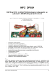
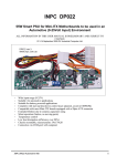
INPC DP022
55W Smart PSU for Mini-ITX Motherboards to be used in an
Automotive (9-25Volt Input) Environment
ALL INFORMATION IN THIS USER MANUAL IS PRELIMINARY AND SUBJECT TO CHANGE.
R 2.02 September 2008
DV Industrial Computer Ltd.
•
•
•
•
•
•
•
•
•
•
Wide input range (9-25V)
Suitable for automotive applications
Suitable for battery powered applications
Complete with start-up/shut-down control (user adjusted, saved in EEPROM)
Compatible with most Mini-ITX boards equipped with a 20pin ATX connector
Silent operation (fanless, no moving parts)
Temperature control
Low heat dissipation (efficiency over 90%)
Chassis mountable, measurements: 34x170x24
Connection via COM-port with computer
Notice
This device should be attached and tuned by specialized personnel only after familiarizing with
current manual! Please take a moment and read this manual before you install the DP022 in your
vehicle. Often rushing into installing the unit can result in serious damage to your DP022 converter,
computer and probably your car electrical system. The DP022 converter has several wires that need
to be installed in various places. When installing, always double check the polarity of your wires
with a voltmeter and by sight.
INPC DP022 Automotive PSU
1
Introduction
This manual is intended for firmware release 2.02. The firmware release number is written on the
label stick on the MCU inside the device and also this number can be obtained by a proper
command sent through the serial line.
All registered trademarks are the property of their respective owners.
Overview
The DP022 is a fully compliant ATX power supply designed to power a low power PCs from a
single 12V power source. The DP022 power supply has an MCU that controls and monitors various
functions of the power supply operation. Also, it realizes voltages monitoring, temperature
monitoring and communication via COM-port with computer. As well the MCU realizes a
WatchDog timer to supervise the computer. A LED
Battery
indicator in the power supply continually reports the
9..25V
power system status and health. It is also used for
troubleshooting. There are four main operating modes of
- + Ignition RS232 (COM)
the DP022 - Deep Sleep, Sleep, Standby, Power On. The
PowerOn
DP022 has user selectable MCU driven timing settings,
Button
allowing you to choose various ignition/shutdown vehicle
computer timing schemes (settings). These settings are GND
user adjusted and saved in EEPROM. These settings
Buck/Boost
allow to overcome the main problems of vehicle
converters
computer power supplying. One of most difficult tasks of
and AT X
MCU
power logic
operating a computer in a vehicle is power consumption
OUT P UT S:
while the computer is OFF. Even if your computer is
LED
+5Vsb, +5V,
totally OFF (standby mode), a computer will still
+3.3V, +12V, -12V
consume a few hundred milliwatts, needed to monitor
computer ON/OFF status. All power supplies provide
5Vsb (5V standby) so that the motherboard can issue at
least a PSON signal. When the computer is in the
ON/OFF
RESET
suspend/sleep mode, it will consume even more power,
20pin AT X connector switch
switch
because the RAM needs to be powered at all times. The
power consumption in the suspend mode is few Watts.
Motherboard
No matter how big your car battery is, it will eventually
drain your vehicle battery in a matter of days. The DP022
is addressing these issues by cutting off the 5VSB rail
after a pre-defined amount of time (timing settings). The
DP022 monitors battery voltage to protect against deep discharge. When battery level drops below
predefined value for more than predefined time, the DP022 will shut down and re-activate only
when the input voltage is > predefined value.
Of course, there is a traditional PC PSU mode setting with no ignition control (shutdown logic
bypassed) and it can be used in non-vehicle computer applications.
INPC DP022 Automotive PSU
2
Input Characteristics
Iutput Connector 2 pin ( PWL3)
Minimum Input Operating voltage 9V (8,5V for less than 0.01sec )
Maximum Input Operating voltage 25V (30V for less than 0.01sec)
Maximum Input Current (Sleep Mode) 20mA
Maximum Input Current (Deep Sleep Mode) 5mA
Range of Adjustable Lower Voltage Threshold 9~15V
Output Power Characteristics
Output Connector ATX Power 20 pin (Molex P/N 39-01-2200)
Maximum Power (at 13.5V Input – engine is running)
Current (Max)
Current Peak
Regulation
(<5 seconds)
Output Rail
5Vsb
6A*
8A*
3%
5V
6A*
8A*
3%
3.3V
6A
8A
3%
12V
2A
2.5A
3%
0.15A
10%
-12V
0.1A
*Total current on 5Vsb and 5V rails
Maximum Power (at 12.5V Input – engine is off)
Current (Max)
Current Peak
Regulation
(<5 seconds)
Output Rail
5Vsb
6A*
7A*
4%
5V
6A*
7A*
4%
3.3V
6A
7A
4%
12V
1.5A
2.0A
4%
-12V
0.1A
*Total current on 5Vsb and 5V rails
0.15A
10%
Output Rail
Maximum Power (at 10V Input – engine cranks or deep discharge)
Current (Max)
Current Peak
Regulation
(<5 seconds)
5Vsb
5A*
6A*
5%
5V
5A*
6A*
5%
3.3V
5A
6A
5%
12V
1.0A
1.5A
5%
-12V
0.1A
*Total current on 5Vsb and 5V rails
0.15A
10%
INPC DP022 Automotive PSU
3
Connection
NOTICE! Use the DP022 only with low power motherboards (all VIA C3/C7 CPUs and
Pentium-M / Atom) that use V(core) from the 5V rail. Do not use general purpose
motherboards or 5.25” CDDs as they tend to use a lot of current on the 12V rail. It's desirable to
use 2.5” drives, SlimCDDs or FlashDisks as they use only current from the 5V rail. Do not
connect a Car Battery Charger directly to the DP022.
The DP022 has several wires that need to be installed in various places. When installing, always
double check the polarity of your wires with a voltmeter. NEVER use the cigarette plug as a
power source; often the contacts are not capable of delivering high current to your PC.
AT FIRST!
Connect a 2-pin jumper cable between JP2 and the motherboards "Reset" header. This will allow
the DP022 to reset the motherboard by simulating a reset button press (POLARITY MATTERS
HERE).
Connect a 2-pin jumper cable between JP3 and the motherboards "Power On" header. This will
allow the DP022 to turn on and off the motherboard by simulating a power button press
(POLARITY MATTERS HERE).
JP6 is a 10-pin polarized connector that is used for connection via serial line (RS-232) to the COMport of the computer. The DP022 uses the RTS/CTS hardware handshaking of serial line flow
control. However, the DP022 ignores signal on RTS line assuming that control computer is always
ready to receive data. Therefore, really only four-wire link is required – SG (Signal Ground),
SIN(RD) (Serial Input/Read of data), SOUT(TR) (Serial Output/Transmit of data), CTS( Clear To
Send). Connect a 10-pin flat ribbon cable to COM port connector of your control computer.
RT1 (2-pin connector) is used to connect remote (0.4m) temperature sensor (thermistor). Place
remote thermistor at CPU heatsink of your computer.
Connect the ATX Power Connector JP8 to the motherboard and any peripherals to JP9 connector.
AT THE END!
Connect the “ground”, IGNITION+ and 12 Volt supply (JP1). One should to fully appreciate the
function of the IGNITION+ signal (pin 2). At the moment immediately after 12V supply voltage
was applied (a battery was connected) the DP022 analyses the value of this signal. If the
IGNITION+ signal is lower than 0.5V then the DP022 will switch to the “VEHICLE MODE”. Else,
if the IGNITION+ signal is higher than 3V at the moment when the supply voltage was applied
the DP022 will switch to the “DUMB MODE”. You should eliminate the situation when this
voltage is between 0.5~3V (as not defined) because the DP022 will define mode not stable. The
DP022 has build-in pull-up of the IGNITION+ signal therefore in order to switch to the “DUMB
MODE” you may leave the IGNITION+ signal free and do not connect it at the moment when the
supply voltage is being applied. And vice versa, in order to switch to the “VEHICLE MODE” you
must keep the IGNITION+ signal closed to the “ground” or GND (pin 3 of JP1) or provide the
IGNITION+ signal voltage level less than 0.5V by corresponding current load at the moment
when the supply voltage is being applied. One should to fully appreciate the fact that the DP022
can define its further mode of operation SOLELY AT THE MOMENT when the supply voltage
is being applied and can be switched from the mode to mode by taking off and second applying the
supply voltage with prior the IGNITION+ signal change. Later, while it is working, the DP022
analyses the “ignition” line of vehicle and controls switching on/off logic and powering of the
INPC DP022 Automotive PSU
4
motherboard only if is switched to the “VEHICLE MODE”. If the DP022 has been switched to the
“DUMB MODE” when the supply voltage is being applied then the “ignition” line has the same
action as the “POWER” button because this line is paralleled for analyse to the “POWER” button.
If the “Ignition Key” is opened then it is the same that the “POWER” button is pressed but if the
“Ignition Key” is closed then it is the same that the “POWER” button is released.
The DP022 can be tested in the lab before being installed into the vehicle. The picture shown below
explains how to do it and is in use for testing and reseach of the DP022. Certain details need to be
noted for proper bench testing. When connecting bench power use between 12 to 16 Volts DC to
POWER (+) and GND (BATTERY) (-) terminals for best results. The best way to do successful
bench testing is to use an adequately sized 12V battery. Bringing in the battery from the car or using
an extra one that has at least a 10-AmpHour capacity will be sufficient in most cases. To aid in
bench testing, it is enough do not connect IGNITION+ anywhere. The DP022 will operate as
“dumb PSU” with button “POWER” control. Ri resistor (10k) simulate load in the “ignition” line of
vehicle. Because of this resistor the voltage value will less than 0.5V if the “Ignition Key” is
released.
In order to connect to 12V vehicle circuit the first you should connect the GND line of the JP1
connector directly to the automotive batteries (–) terminal with heavy gauge wire. GND may also be
connected with vehicle chassis if desired. Then connect the IGNITION+ (pin 2 of JP12) to the
switched +12 Volt supply wire (“ignition” circuit or fuse box). This will bypass the
Startup/Shutdown sequence and battery protection. At the end connect POWER line of JP1
connector directly to the automotive batteries (+) terminal with heavy gauge wire.
Apply 12 Volts to IGNITION+ by turning on the ignition or by flipping a switch and you’re ready
to go!
Do not connect IGNITION+ anywhere if you use the DP022 as a non-vehicle PSU. In this case
the DP022 will operate as “dumb PSU”.
INPC DP022 Automotive PSU
5
INPC DP022 Automotive PSU
6
Operation
“VEHICLE MODE”
If ignition is OFF and the IGNITION+ signal is LOW (about 0 Volts), then nothing happens and the
DP022 stays in Sleep mode (LED Blinks as 0.03sec On / 1sec Off). The DP022 is waiting for
“ignition” signal. The user steps into the automobile and turns on the key. IGNITION+ goes HI (12
Volts) and as a result the DP022 wakes up from Sleep Mode. The DP022 waits for 4 seconds, then
turns on the 5Vsb rail. After another second the DP022 sends an “ON” signal to the motherboard
via the 2 wires connected to the JP3 and to the motherboard’s “Power On” header. The motherboard
will turn ON and your system should start booting. Ignition is ON during driving. Your computer
will remain ON playing MP3s, doing GPS Navigation, etc. The automobile goes to the gas station
and the driver turns off the key and IGNITION+ goes LOW. The DP022 now starts the Countdown
Timer T1. The driver gets back in the car, starts the car and the computer keeps playing the MP3s
without a hiccup. The user then drives home and turns off the car for the night. IGNITION+ goes
low and the Countdown Timer T1 starts. The DP022 waits for “STANDBYDELAY” - then
Countdown Timer T1 expires. The DP022 then sends a pulse again over JP3 pins to shutdown the
computer. The shutdown pulse was successful and the computer turned off (Standby). The
Countdown Timer T2 starts. The DP022 waits for “SLEEPDELAY” - then Countdown Timer T2
expires. The DP022 then goes to Sleep mode and preserves battery power. While in Deep Sleep or
Sleep mode, the DP022 constantly monitors your car battery voltage levels, preventing deep
discharge situations by automatically shutting down until battery levels reach safe levels again.
“DUMB MODE”
The DP022 behaves as a regular ATX PSU with button “Power On/Off”. Of course, the DP022
monitors battery voltage to protect against deep discharge and monitors temperature and outputs.
You can monitor these parameters via serial line in “DUMB MODE” as well as in “VEHICLE
MODE”. Also, the WatchDog timer can be used. So, it seems that the DP022 is not a regular ATX
PSU.
LED Status Codes
LED
Buzzer
Status
2 x 0.03sec Blink / 2sec Off
0.03sec Blink / 2sec Off
Deep Sleep
2 x 0.03sec Blink / 2sec Off
0.03sec Blink / 2sec Off
Sleep
2 x 0.03sec Blink / 1sec Off
0.03sec Blink / 1sec Off
StandBy
On
1sec Blink / 0.03sec Off
PowerOn
2 x 0.03sec Blink / 4sec Off
0.03sec Blink / 4sec Off
Sleep Over Temperature
2 x 0.03sec Blink / 4sec Off
0.03sec Blink / 4sec Off
Sleep PSU Overload or Fault*
Input Voltage must go low or 'r' command must be sent to clear a fault
INPC DP022 Automotive PSU
7
Serial Line (RS232)
Notice! The DP022 PSU operates completely independent of computer's software and serial line
connection.
The DP022 that is connected to control computer by serial line, operates as a terminal device with
fixed connection 9600, 8 bit, no parity, 1 stop bit. Usually, computer acts as initiator of data
communication – the host. The computer can send commands and data to the DP022. The DP022
responds by data block to the most commands sent from computer. The DP022 realizes a likeness
of ANSI/VT100 terminal by means of subset of commands with extensions for WatchDog timer,
temperature and voltage measurement channel and so on. Input from serial line is latched by
incoming buffer of 23 byte size. String with 24 bytes and more will be wrapped. The DP022 starts
parsing after receiving of CR(0x0d) or LF(0x0a) symbol or after overflowing of input buffer (23
bytes). Note that parameters, such as timeout for the WatchDog timer, are in ASCII digits, so 12 is
represented by the characters “1” and “2”, not by a single byte with the value of 12. Also, characters
are case sensitive, so /W and /w are two different commands.
WatchDog timer
The WatchDog timer is designed to overpass a computer hanging up. Usually computer almost
never hangs up. However, if it hangs up and gets stuck, usually there is nobody at the site to press
the reset or nobody knows where the stuck computer is because there were no problem with it for a
long time. The WatchDog timer is used just for such situations. It automatically restarts the
computer that is hung up. To restart computer, the WatchDog timer closes circuit between pins 1
and 2 of JP2 connector. The WatchDog timer is off after starting of the DP022. To switch it on, the
command “/WW” should be sent and timeout (number of ticks, one tick is 0.3 seconds) should be
set by indicating required W, which is a value between 0 and 255. The driver program needs to set
the timeout periodically to avoid the WatchDog hits and following “reset” contacts closing.
Detailed information about WatchDog is given in the further sections.
INPC DP022 Automotive PSU
8
Using the serial line of
the DP022
in
MS Windows
(MS Windows XP for example)
Assume that computer has available COM3 port that should be set as 9600, 8 bit, no parity, 1 stop
bit operation. As a dialog application let us use Hyper Terminal that is included in MS Windows.
To get it ready, open the folder Communications and run Hyper Terminal (click on “Start”
button and then Programs - Accessories – Communications. The dialog window appears on the
screen. Let us name our connection as PSU (arbitrary name) :
Then, select connection via serial port COM3 in Connect To dialog window:
INPC DP022 Automotive PSU
9
And set up COM3 properties:
Click on File button in main menu of Hyper Terminal program and click on item Properties in pop
up menu. In dialog window PSU Properties select bookmark Settings and select the following
properties:
INPC DP022 Automotive PSU
10
When Hyper Terminal configuration has been finished, everything is ready to dialog with the
controller. Commands that are entered on terminal keyboard are sent to the controller PSU via serial
port while input data flow is displayed on terminal window. In the clear terminal window enter the
first command h (help) – press keys h and then Enter. As a response the controller sends firmware
release number and list of commands that are supported in «Monitor» mode:
If you see this list, all settings have been made correct and you can continue with study of
commands. The commands have friendly interface to interact with terminal program. NOTICE! The
commands that start with symbol “/” (slash) are focused to be used with dedicated programs (of
course, you can use them with terminal program). Some of commands answer with asked value, but
some of commands do not. All answers that have started with symbol “/” are tailed with symbol
“/”, carriage return, line feed and prompt symbol “>”
- a (display all)
Press two keys a and Enter. As a response, the DP022 sends current value of temperature, output
voltages, input voltage, value of Lower Voltage Threshold, contents and initial values of Timers T1
and T2, current operating mode and status:
/b (get “STANDBYDELAY”)
Press three keys / b and Enter. As a response, the DP022 sends current value of
“STANDBYDELAY” – initial value for T1 timer (in seconds). This value should be loaded into
counter of T1 timer when IGNITION+ goes low. After that T1 timer starts time countdown. The
DP022 switches to StandBy state when T1 timer expires. The “STANDBYDELAY” value has
been saved in EEPROM.
INPC DP022 Automotive PSU
11
/B (set new value of “STANDBYDELAY”)
Press keys / B and then type value of seconds from 0 to 255 and finish with Enter. You can check
accuracy of setting by /b command (get “STANDBYDELAY”). If you set “STANDBYDELAY”
to 0, then the DP022 will switch to StandBy state immediately after circuit IGNITION+ has gone
low.
/cb (get counter value of T1 timer”)
Press four keys / c b and Enter. As a response, the DP022 sends current value of T1 timer counter
(in seconds). At the moment when IGNITION+ goes low while the DP022 is being in PowerOn
state - T1 timer starts decrementing (counter value count down). Therefore, second command that
can be sent with delay of some time will result in another value with difference that corresponds to
delay from first command point.
/cs (get counter value of T2 timer”)
Press four keys / c s and Enter. As a response, the DP022 sends current value of T2 timer counter
(in seconds). At the moment when the DP022 switches into StandBy state T2 timer starts
decrementing (counter value count down). Therefore, second command that can be sent with delay
of some time will result in another value with difference that corresponds to delay from first
command point.
/e (get “SLEEPDELAY”)
Press three keys / e and Enter. As a response, the DP022 sends current value of “SLEEPDELAY”,
initial value for T2 timer (in seconds). This value should be loaded into counter of T2 timer when
the DP022 switches into StandBy state. After that T2 timer starts time countdown. The DP022
switches to Sleep state when T2 timer expires. The “SLEEPDELAY” value is being stored in
EEPROM.
/E (set new value of “SLEEPDELAY”)
Press two keys / E and then type value of seconds from 0 to 255 at finish with Enter. You can check
accuracy of setting by /e command (get “SLEEPDELAY”). If you set “SLEEPDELAY” to 0 then the
DP022 will switch to StandBy state at no time.
/f (get “CONFIGURATION”)
Press three keys / f and Enter. As a response, the DP022 sends current value of
“CONFIGURATION” – either 0 or 1. If the value is 1, then the DP022 is configured for restart in
case of recovery after a special kind of errors – revised. The first of revised errors is - overheating –
the error that appears when even one of two thermistor will reach 65 ОC but disappears when both
thermistors will be below 55ОC. The second error is – input voltage is lower than Low Voltage
Threshold - the error that appears when input (battery) voltage will drop lower than Low Voltage
Threshold but disappears when input voltage will rise above Low Voltage Threshold value more
than value of Voltage Threshold Hysteresis. The “CONFIGURATION” value has been saved in
EEPROM.
/F (set new value of “CONFIGURATION”)
Press two keys / F and then type value of either 0 or 1 at finish with Enter. You can check accuracy
of setting by /f command (get “CONFIGURATION”). If you set “CONFIGURATION” to 0 then
the DP022 will not restart after recovery and will stay in mode Sleep Over Temperature/ PSU
Overload or Fault till the 'r' command has been sent or input voltage is off even over temperature or
low input voltage error has been recovered.
INPC DP022 Automotive PSU
12
/gl (get Low Voltage Threshold) Trip Threshold Low Voltage
Press four keys / g l and Enter. As a response the DP022 sends value of Low Voltage Threshold (in
millivolts). The DP022 switches into Sleep PSU Overload or Fault state if input voltage does not
exceed Low Voltage Threshold. The Low Voltage Threshold value is being stored in EEPROM.
/Gl (set new value of Low Voltage Threshold) Trip Threshold Low Voltage
Press keys / G l and then type value of millivolts from 9000 to 1500 and finish with Enter. You can
check accuracy of setting by /gl command (get Lower Voltage Threshold).
/gh (get Voltage Threshold Hysteresis) Hysteresis Low Voltage
Press four keys / g h and Enter. As a response the DP022 sends value of Voltage Threshold
Hysteresis (in millivolts). In case if the DP022 has been switched to Sleep PSU Overload or Fault
state (and this error was caused by dropping of input voltage below Low Voltage Threshold value)
and if the input voltage stays less than sum of Low Voltage Threshold and Voltage Threshold
Hysteresis, the DP022 will stay in Sleep PSU Overload or Fault state. If input voltage rises over
sum of Low Voltage Threshold and Voltage Threshold Hysteresis, the DP022 will switch into
StandBy state. The Low Voltage Threshold value is being stored in EEPROM.
/Gh (set new value of Voltage Threshold Hysteresis) Hysteresis Low Voltage
Press keys / G h and then type value of millivolts from 500 to 4000 and finish with Enter. You can
check accuracy of setting by /gh command (get Voltage Threshold Hysteresis).
h (get list of commands)
Press two keys h and Enter. As a response, the DP022 sends firmware release number and list of
commands.
l (get launching voltages table)
Press two keys l and Enter. As a response, the DP022 sends the 20-row table with values of
voltages that were measured at the moment of starting the DP022. Table contains 20 batches of
voltages measured with 1 ms time slots (each batch reflected in separate row). At the start there was
20ms period to control. This table helps to evaluate load that has been connected to the DP022.
/m (get current mode of operation)
Press three keys / m and Enter. As a response, the DP022 sends numeric value that corresponds to
current mode of operation – either 0 (if DUMB MODE has been set) or 1 (if VEHICLE MODE has
been set).
/n (get firmware release number)
Press three keys / n and Enter. As a response, the DP022 sends firmware release number.
INPC DP022 Automotive PSU
13
/s (get current state)
Press three keys / s and Enter. As a response the DP022 sends numeric value that corresponds to
current state. The correspondence table looks as following:
Value
Status
Explanation
0
PowerOn
Switched on, all rails have been activated.
2
StandBy
Switched off, only 5Vsb rail has been activated.
7
Sleep
Switched off, any rail has not been activated.
8
Deep Sleep
Switched off, any rail has not been activated.
9
Sleep Over Temperature
Switched off, any rail has not been activated.
10
Sleep PSU Overload or Fault Switched off, any rail has not been activated.
r (reset “error” state and switch to StandBy state)
Press two keys r and Enter. As a response, the DP022 resets the “error” state and switches into
StandBy state.
/t (get current value of temperature)
Press three keys / t and Enter. As a response, the DP022 sends two values of temperature that aree
separeted by “/” symbol (slash). First value is measured by remote thermistor, second is measured
by internal DP022 thermistor. You can control temperature on-the-fly by sending this comand
periodically.
/u (get “STARTUPDELAY”)
Press three keys / u and Enter. As a response, the DP022 sends current value of
“STARTUPDELAY”, value of delay for startup timer (in seconds) that the DP022 make as pause
after input voltage 12V has been applied. The “STARTUPDELAY” value is being stored in
EEPROM.
/U (set new value of “STARTUPDELAY”)
Press two keys / F and then type value of seconds from 0 to 255 at finish with Enter. You can check
accuracy of setting by /u command (get “STARTUPDELAY”).
/v (get current values of input and output voltages)
Press three keys / v and Enter. As a response, the DP022 sends five values of voltages that are
separated by “/” symbol (slash). First value is input voltage (nominal value is 13.5V), second value
is 5Vsb, third - 12V, fourth - 5V and fifth - 3,3V. Values have sent in millivolts. You can control
voltages on-the-fly by sending this comand periodically.
/w (get current value of counter of WatchDog timer)
Press two keys w and Enter. As a response, the DP022 sends current value of counter of WatchDog
timer (in ticks, each tick is 0.3s long).
/W (set current value of counter of WatchDog timer)
Press two keys / W and then type the value of ticks from 0 to 255 (each tick is 0.3s long) and finish
with Enter. As a response, the DP022 sends “/” symbol (slash) and just entered value which allows
to check accuracy of setting.
INPC DP022 Automotive PSU
14
Configuring your operating system to be able for safe
shutdown/standby with control from the DP022
(MS Windows XP for example)
NOTE: In order to realize such control ACPI (Advanced Configuration and Power Interface)
should be used that is not a plug and play function. If ACPI is not enabled at the time your MiniITX motherboard is configured, you should enable it before your operating system configuring as
shown below:
Go into ‘BIOS SETUP UTILITY’ (usually you have to power-up the computer and press
the 'DEL' key on keyboard). Go to the ‘Power’ tab, then into 'APM' (Advanced Power
Management) option and select 'Enabled'. Also, select 'Enabled' for HDD. Go back into
'Power' tab and select 'S3 State' for 'ACPI' Suspend State. If an application you have used
or motherboard does not support standby mode then select ‘S1 state’. Save all changes
you have made and exit from BIOS setup utility.
If ACPI is not enabled at the time OS Windows is installed, you should install as shown below:
Click “Start” then <Settings> and <Control Panel>, then double click <Add/Remove
Hardware> icon as result let Windows automatically detect ACPI (if it is enabled at the
time your Mini-ITX motherboard BIOS is configured). Then install the proper drivers
(you may need the original Windows CD). Reboot the computer to detect the newly
installd ACPI component.
Then you have to configure Shutdown or Standby mode of operation for OS Windows as shown
below:
Click “Start” then <Settings> and <Control Panel>, then double click <Display> icon
as result access <Display Properties> window. Click <Screen Saver> tab and click
<Power> button to access <Power Option Properties> window. Click <Hibernate>
tab, check box [x] <Enable Hibernate support>, click <Apply>. Click <Advanced>
tab and click down arrow to open choices <Under Power buttons> (of <When I press
the power button on my computer>), select one of three choices Standby, Hibernate
or Power-off options. Come back to <Power Option Properties> window and select
<Portable/Laptop> under <Power schemes> and click <Apply>. Then shutdown the
computer: click “Start” and <Shut Down> under <ShutDown> window.
INPC DP022 Automotive PSU
15
Support and warranty
Standard Hardware Warranty 1 Year.
Installation support: 30 days via email.
INPC DP022 Automotive PSU
16