1
US006914534B2
(12)
United States Patent
(10) Patent N0.:
US 6,914,534 B2
(45) Date of Patent:
Jul. 5, 2005
Tanguay
(54)
ENHANCED VISUAL SIGNALING FOR AN
6,329,924 B1 * 12/2001 McNulty .................. .. 340/660
ADVERSE CONDITION DETECTOR
6,426,703 B1 *
(75) Inventor:
.
William P. Tanguay, Downers Grove,
IL (Us)
OTHER PUBLICATIONS
First Alert, Model SC01N—User’s Manual, 10/99.
_
“AC Powered Smoke And Carbon Monoxide Alarm With
(73) Asslgnee- 212g]: ?hzllsjesfompany’ Downers
Battery Back—Up And Silence Feature”, Model SC 6120B
’
( * ) Notice:
7/2002 Johnston et a1. .......... .. 340/628
User’s Manual, BRK Electronics, pp. 1—30, Jan., 2002.
Subject' to any disclaimer, the term of this
* Cited by examiner
patent is extended or adJusted under 35
U-S-C- 154(k)) by 140 days-
Primary Examiner—Jeffery Hofsass
Assistant Examiner—Jennifer Stone
(21) Appl. N0.: 10/300,386
_
(74) Attorney, Agent, or Firm—Andrus, Sceales, Starke &
SaWall, LLP
(22) Filed:
Nov. 20, 2002
(65)
Prior Publication Data
_
_
_
(57)
ABSTRACT
An adverse condition detector that alloWs the user to visu
US 2004/0095253 A1 May 20’ 2004
ally determine the type of adverse condition being detected.
(51)
Int. Cl.7 .............................................. .. G08B 17/10
The adverse condition detector includes a sensor and a
(52)
US. Cl. ................ .. 340/628; 340/286.05; 340/577;
340/815_45
Field of Search .......................... .. 340/628, 286.05,
Control unit Coupled to the Sensor- When the Sensor detects
an adverse condition above a selected level, the control unit
generates an audible alarm Signal and a Visual alarm Signal
340/532, 531, 42624, 5542, 53926, 577,
The visual alarm signal simulates the type of adverse
632, 517, 81545, 81565, 81573
condition being detected. In one embodiment of the
invention, the visual alarm signal includes a plurality of
visual indicators operated in a random fashion to simulate
(58)
(56)
References Cited
the appearance of a ?ame.
U.S. PATENT DOCUMENTS
5,526,280 A
*
6/1996 Consadori et a1. .......... .. 702/24
23 Claims, 4 Drawing Sheets
20
18
e
1 0 f’
Q
.._\r
‘I
‘r
‘1
1;!
a,°°=vq
°
°-
u°v.'o'
qvaaw'~o.oh
Q
‘0'0" :1’, 'v":?.<:-° f',n°a'md-.f’_ a4.
1.1..’ °__a 0.0-- a. ‘.0 A‘--' o°_16uD'°.°
0
0.
00d.
_qvnob'.a~
{{JJG’.
'°°-'u‘u°.~5.°n~<lo°di
_-
v.
ob“..
U.S. Patent
Jul. 5,2005
Sheet 3 0f 4
90
|f92 [94 [96
+0.5 sec.
US 6,914,534 B2
‘299
+1.5 590+
4.0 sec.-————>»
FIG. 3
FIG. 6
U.S. Patent
Jul. 5,2005
Sheet 4 0f 4
120
122
118
L,\
I
116/“ I
4r/114
112
,
J
112
‘
r-1
110
US 6,914,534 B2
QT
\\ ll
\\
(
112
I
,
j
64
US 6,914,534 B2
1
2
ENHANCED VISUAL SIGNALING FOR AN
ADVERSE CONDITION DETECTOR
Various other manufacturers have used different color
LEDs to indicate the tWo types of alarm conditions being
sensed. Although the tWo types of LEDs for the tWo types of
BACKGROUND OF THE INVENTION
to differentiate the tWo types of alarm signals, the LEDs are
adverse conditions being sensed provide a reliable technique
typically positioned Within a cutout that must be visually
examined by the user to determine What type of signal is
The present invention generally relates to an adverse
condition detector that includes a sensor for detecting an
being generated. Therefore, if the alarm signals are being
adverse condition in a building. More speci?cally, the
present invention is directed to a method and apparatus for
providing an enhanced visual alarm signal such that the user
can more quickly and easily determine What type of adverse
generated in a dark building, it is dif?cult for the user to
immediately associate the visual signal being generated With
one of the types of adverse conditions being sensed.
Yet another manufacturer has developed a combination
alarm that includes a single red LED that ?ashes When either
the CO audible temporal signal or the audible smoke tem
condition is being sensed by the adverse condition detector.
Alarm systems that detect dangerous conditions in a home
or business, such as the presence of smoke, carbon dioxide
or other haZardous elements, are extensively used to prevent
death or injury. In recent years, it has been the practice to
develop adverse condition detectors that detect more than
one type of adverse condition Within a single unit. For
15
poral signal is being generated. The red LED ?ashes simul
example, detectors are currently available that include mul
taneously With the horn activation. In addition to the single
?ashing LED, the alarm utiliZes a voice announcement
during the sound betWeen the horn pulses to differentiate the
type of signal. For example, in a smoke event, the alarm tone
tiple sensors, such as a CO sensor and a smoke sensor, such
sounds and the message “Fire! Fire!” is relayed. LikeWise,
in a CO event, the alarm tone sounds and a user hears the
that if either of these adverse conditions is detected, the
single adverse condition detector can generate an audible
Warning “Warning! Carbon Monoxide”. Although this type
alarm signal to the user indicating the type of adverse
of alarm system Works Well With a user that understands
condition being detected.
Presently, combination adverse condition detectors that
English, a non-English speaking user Would be unable to
25
distinguish the types of alarms being generated.
Therefore, a need exists for an improved method of
alerting a user of an adverse condition detector of the type
sense both the presence of CO and smoke emit different
audible alarms depending upon the type of adverse condition
being detected. The smoke alarm audible signal is de?ned by
of adverse condition being detected by the detector during
UnderWriters Laboratory and is referred to as the Universal
an alarm condition. Speci?cally, a need exists for an adverse
Evacuation Signal. The Universal Evaluation Signal has
three moderate length tones separate by tWo moderate length
condition detector that generates a visual signal that alloWs
the user to immediately associate the visual signal With the
pauses and a third longer pause, With the entire process
type of adverse condition being detected.
repeating every four seconds.
In contrast, the CO temporal audible signal de?ned by UL
includes four very rapid pulses occurring in less than one
SUMMARY OF THE INVENTION
35
second With a pause of about ?ve seconds until the next
sequence of pulses. Thus, the tWo audible signals can be
distinguished by a user that is aWare of the different sounds
for each of the audible alarm signals. HoWever, a limitation
40
The present invention provides an adverse condition
detector that generates a visual alarm signal that simulates
the type of adverse condition being detected such that a user
is able to visually determine the type of adverse conditions
present. The detector of the invention includes a control unit
exists in that the user of the adverse condition detector must
coupled to an adverse condition sensor that is operable to
knoW and be able to distinguish the tWo types of audible
detect an adverse condition in an area near the detector.
alarms generated by the single adverse condition detector.
When an adverse condition is detected, the control unit
generates an audible alarm signal through an audible
indicator, such as a horn, coupled to the control unit. In one
embodiment of the invention, the audible alarm signal has a
Since many users only hear the tWo different audible
patterns during a manual test of the detector, these users are
unable to remember and distinguish the tWo different audible
alarm patterns during an alarm situation. Thus, many manu
facturers have determined that the use of a visual signal in
addition to the audible alarm signal is an effective manner to
45
series of repeating alarm periods each having a plurality of
alarm pulses separated by an off periods.
During generation of the audible alarm signal, the control
communicate to the user the type of alarm signal being
generated by a single multi-sensor adverse condition detec
unit generates a visual alarm signal that indicates to the user
tor.
With the present invention, the visual alarm signal visually
the type of alarm condition being detected. In accordance
One example of a combination alarm having differing
visual signals is the BRK Model No. SC01SCL. In this
product, a red LED is simultaneously ?ashed With the smoke
alarm signal to indicate to the user that the device is sensing
smoke. The red LED is positioned behind a red plastic lens
that in turn is positioned behind a cutout in the detector
housing that resembles a ?ame. Thus, the user is led to
associate the smoke audible alarm signal With the ?ashing of
the red LED behind the ?ame cutout. Similarly, the device
uses another separate red LED positioned behind a triangle
shaped cutout that simulates the shape of a molecule of gas.
The second red LED is ?ashed along With the generation of
the CO alarm signal such that the user can visually associate
55
simulates the type of adverse condition triggering the alarm
such that the user can quickly and easily determine the type
of adverse condition being detected.
The adverse condition detector of the present invention
includes a plurality of visual indicators each coupled to the
control unit. Each of the visual indicators can be operated
independently by the control unit. Preferably, the visual
indicators each are capable of generating a different color
light than the remaining visual indicators such that the visual
indicators can be selectively operated to generate changing
light colors.
During detection of the adverse condition, the control unit
65
sequentially ?ashes the visual indicators on and off in a
the ?ashing of the red LED behind the molecule cutout as a
pattern that simulates the type of adverse condition being
CO sensing.
detected. In one embodiment of the invention, the visual
US 6,914,534 B2
3
4
indicators are three different colored LEDs. In an embodi
ment in Which the adverse condition detector is a smoke
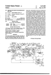
adverse condition detector 18 is located in each of the rooms
of the facility 10 and the detectors 18 are interconnected by
a pair of common conductors 20. The plurality of adverse
alarm, the three LEDs are selected from the colors orange,
yelloW and red, such that the LEDs can simulate the appear
condition detectors 18 can communicate With each other
through the common conductors 20.
ance of a ?ickering ?ame.
The microprocessor control unit of the adverse condition
detector includes a stored operational sequence that de?nes
the sequence of operation of the visual indicators.
Preferably, the operational sequence alloWs the control unit
to operate only one visual indicator at a time in order to
conserve the poWer supply for the detector.
10
The operational sequence stored in the microprocessor
control unit includes directions to ?ash each of the visual
indicators on for only an activation period. After the expi
ration of the activation period, another of the visual indica
tors is ?ashed on for another activation period. Preferably,
the activation period is short in duration and numerous
detector (e.g., ioniZation, photo-electric) for detecting
smoke indicating the presence of a ?re. Other detectors
could include but are not limited to carbon monoxide
15
detectors, aerosol detectors, gas detectors including
combustible, toxic and pollution gas detectors, heat detec
tors and the like.
In the embodiment of the invention to be described, the
adverse condition detector 18 is a combination smoke and
sequential activation periods de?ne the visual alarm signal.
The operational sequence is selected to ?ash the visual
indicators on and off to create a “random” appearance to the
carbon monoxide detector, although the features of the
visual alarm signal.
present invention could be utiliZed in many of the other
detectors currently available or yet to be developed that
In one embodiment of the invention, the visual alarm
signal is generated only during the off period betWeen pulses
of the audible alarm signal. Each off period of the audible
alarm signal is divided into multiple time slots each having
the duration of the activation period such that the visual
indicators can be operated according to the operational
sequence during the off period of the alarm signal.
The generation of the visual alarm signal by the micro
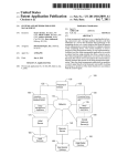
In FIG. 1, each of the adverse condition detectors 18 is
con?gured to detect a dangerous condition that may exist in
the room in Which it is positioned. Generally speaking, the
adverse condition detector 18 may include any type of
device for detecting an adverse condition for the given
environment. For example, the detector 18 could be a smoke
provide an indication to a user that an adverse condition
25
processor control unit alloWs a user to visually examine the
exists.
Referring noW to FIG. 2, thereshoWn is a block diagram
of the adverse condition detector 18 of the present invention.
As described, the adverse condition detector 18 of the
present invention is a combination smoke and CO detector.
The adverse condition detector 18 includes a central
signal and quickly determine the type of adverse condition
being detected. The generation of the visual alarm signal in
microprocessor 22 that controls the operation of the adverse
condition detector 18. In the preferred embodiment of the
invention, the microprocessor 22 is available from Micro
accordance With the present invention does not require the
chip as Model No. PIC16LF73, although other micropro
adverse condition detector during the generation of an alarm
user to have any knoWledge of the audible alarm patterns or 35 cessors could be utiliZed While operating Within the scope of
speak a speci?c language in order to determine the type of
adverse condition being detected.
Various other features, objects and advantages of the
invention Will be made apparent from the folloWing descrip
tion taken together With the draWings.
the present invention. The block diagram of FIG. 2 is shoWn
on an overall schematic scale only, since the actual circuit
components for the individual blocks of the diagram are Well
knoWn to those skilled in the art and form no part of the
40
The draWings illustrate the best mode presently contem
plated of carrying out the invention.
In the draWings:
includes an alarm indicator or transducer 24 for alerting a
user that an adverse condition has been detected. Such an
alarm indicator or transducer 24 could include but is not
45
FIG. 1 is a general vieW of a plurality of remote adverse
condition detectors that are interconnected With a pair of
common conductors;
FIG. 2 is a block diagram of an adverse condition detector
the invention illustrated in FIG. 2, the transducer 24 com
prises a pieZoelectric resonant horn, Which is a highly
ef?cient device capable of producing an extremely loud (85
dB) alarm When driven by a relatively small drive signal.
FIG. 3 is an illustration of the alarm signal produced by
the adverse condition detector of the present invention;
The microprocessor 22 is coupled to the transducer 24
FIG. 4 is an illustration of the sequence of operation of the
?rst smoke LED by the control unit;
55
second smoke LED by the control unit;
As illustrated in FIG. 2, an AC poWer input circuit 28 is
coupled to the line poWer Within the facility. The AC poWer
input circuit 28 converts the AC poWer to an approximately
9 volt DC poWer supply, as indicated by block 30 and
third smoke LED by the control unit; and
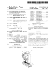
FIG. 7 is a partial section vieW illustrating the mounting
of the smoke LEDs to a printed circuit board and utiliZation
of a light pipe to direct the generated light for vieWing from
referred to as VCC. The adverse condition detector 18
a slot in the detector housing.
FIG. 1 illustrates a facility 10 having multiple levels 12,
14 and 16 With rooms on each level. As illustrated, an
through a driver 26. The driver 26 may be any suitable
circuit or circuit combination that is capable of operably
driving the transducer 24 to generate an alarm signal When
the detector detects an adverse condition. The driver 26 is
actuated by an output signal from the microprocessor 22.
FIG. 6 is an illustration of the sequence of operation of the
DETAILED DESCRIPTION OF THE
INVENTION
limited to a horn, a buZZer, siren, ?ashing lights or any other
type of audible or visual indicator that Would alert a user of
the presence of an adverse condition. In the embodiment of
apparatus of the present invention;
FIG. 5 is an illustration of the sequence of operation of the
present invention.
As illustrated in FIG. 2, the adverse condition detector 18
BRIEF DESCRIPTION OF THE DRAWINGS
includes a green AC LED 34 that is lit to alloW the user to
quickly determine that proper AC poWer is being supplied to
65
the adverse condition detector 18.
The adverse condition detector 18 further includes an AC
test circuit 36 that provides an input 38 to the microproces
US 6,914,534 B2
5
6
sor 22 such that the microprocessor 22 can monitor for the
detection level Within the smoke detector ASIC 54 for a
proper application of AC poWer to the AC poWer input
selected period of time such that the smoke detector ASIC 54
circuit 28. If AC poWer is not available, as determined
Will moderately change the sensitivity of the alarm-sensing
through the AC test circuit 36, the microprocessor 22 can
threshold for the hush period. The use of the hush circuit 58
is Well knoWn and is described in Us. Pat. Nos. 4,792,797
sWitch to a loW-poWer mode of operation to conserve energy
and RE33,920, incorporated herein by reference.
and extend the life of the battery 40.
The adverse condition detector 18 includes a voltage
regulator 42 that is coupled to the 9 volt VCC 30 and
generates a 3.3 volt supply VDD as available at block 44. The
At the same time the microprocessor 22 generates the
smoke alarm signal to the transducer 24, the microprocessor
22 activates a plurality of LEDs 63, 64 and 65 to provide a
voltage supply VDD is applied to the microprocessor 22
through the input line 32, While the poWer supply VCC
operates many of the detector-based components as is
knoWn.
In the embodiment of the invention illustrated in FIG. 2,
the adverse condition detector 18 is a combination smoke
and carbon monoxide detector. The detector 18 includes a
carbon monoxide sensor circuit 46 coupled to the micro
visual indication to a user that the microprocessor 22 is
generating a smoke alarm signal. The speci?cs of the
operation of the LEDs 63, 64 and 65 by the microprocessor
15
alarm is being generated by the microprocessor 22. The
detector 18 further includes a loW-battery LED 66.
When the microprocessor 22 receives the smoke signal on
processor 22 by input line 48. In the preferred embodiment
of the invention, the CO sensor circuit 46 includes a carbon
monoxide sensor that generates a carbon monoxide signal on
line 56, the microprocessor 22 generates an interconnect
input line 48. Upon receiving the carbon monoxide signal on
line 48, the microprocessor 22 determines When the sensed
level of carbon monoxide has exceeded one of many dif
ferent combinations of concentration and exposure time
(time-Weighted average) and activates the transducer 24
25
through the driver 26 as Well as turning on the carbon
monoxide LED 50. In the preferred embodiment of the
invention, the carbon monoxide LED 50 is blue in color,
although other variations for the carbon monoxide LED are
contemplated as being Within the scope of the present
invention.
In the preferred embodiment of the invention, the micro
processor 22 generates a carbon monoxide alarm signal to
the transducer 24 that is distinct from the alarm signal
generated upon detection of smoke. The speci?c audible
pattern of the carbon monoxide alarm signal is an industry
each other and sent into an alarm condition upon detection
of an adverse condition in any of the adverse condition
detectors 18.
Referring back to FIG. 2, the adverse condition detector
18 includes both a digital interconnect interface 74 and a
35
legacy interconnect interface 76 such that the microproces
sor 22 can both send and receive tWo different types of
signals through the I/O port 72. The digital interconnect
40
coupled to the microprocessor through a smoke detector
ASIC 54. The smoke sensor 52 can be either a photoelectric
or ioniZation smoke sensor that detects the presence of
smoke Within the area in Which the adverse condition
detector 18 is located. In the embodiment of the invention
illustrated, the smoke detector ASIC 54 is available from
signal through the I/O port 72. In the preferred embodiment
of the invention, the interconnect signal is delayed after the
beginning of the alarm signal generated to activate the
transducer 24. HoWever, the interconnect signal could be
simultaneously generated With the alarm signal While oper
ating Within the scope of the present invention. The I/O port
72 is coupled to the common conduit 20 (FIG. 1) such that
multiple adverse condition detectors 18 can be joined to
standard and is thus Well knoWn to those skilled in the art.
In addition to the carbon monoxide sensor circuit 46, the
adverse condition detector 18 includes a smoke sensor 52
control unit 22 Will be described in much greater detail
beloW. Thus, the smoke LEDs 63, 64 and 65 and the carbon
monoxide LED 50, in addition to the different audible alarm
signal patterns, alloW the user to determine Which type of
interface 74 is utiliZed With a microprocessor-based adverse
condition detector 18 and alloWs the microprocessor 22 to
communicate digital information to other adverse condition
detectors through the digital interconnect interface 74 and
the I/O port 72.
As an enhancement to the adverse condition detector 18
illustrated in FIG. 2, the legacy interconnect interface 76
45
alloWs the microprocessor 22 to communicate to so-called
“legacy alarm” devices. The prior art legacy alarm devices
issue a continuous DC voltage along the interconnect com
Allegro as Model No. A5368CA and has been used as a
smoke detector ASIC for numerous years.
When the smoke sensor 52 senses a level of smoke that
mon conduit 20 to any interconnected remote device. In the
event that a microprocessor-based detector 18 is utiliZed in
exceeds a selected value, the smoke detector ASIC 54
the same system With a prior art legacy device, the legacy
generates a smoke signal along line 56 that is received
Within the central microprocessor 22. Upon receiving the
interconnect interface 76 alloWs the tWo devices to commu
nicate over the IO port 72.
smoke signal, the microprocessor 22 generates an alarm
signal to the transducer 24 through the driver 26. The alarm
microprocessor 22 through the input line 80. The test
signal generated by the microprocessor 22 has a pattern of
alarm pulses folloWed by quiet periods to create a pulsed
A test equipment interface 78 is shoWn connected to the
55
the microprocessor and to possibly modify the operating
alarm signal as is standard in the smoke alarm industry. The
details of the generated alarm signal Will be discussed in
much greater detail beloW.
As illustrated in FIG. 2, the adverse condition detector 18
includes a hush circuit 58 that quiets the alarm being
instructions contained Within the microprocessor 22.
An oscillator 82 is connected to the microprocessor 22 to
control the internal clock Within the microprocessor 22, as is
conventional.
generated by modifying the operation of the smoke detector
During normal operating conditions, the adverse condi
ASIC 54 upon activation of the test sWitch 60. If the test
sWitch 60 is activated during the generation of the alarm
signal due to smoke detection by the smoke sensor 52, the
microprocessor 22 Will output a signal on line 62 to activate
the hush circuit 58. The hush circuit 58 adjusts the smoke
equipment interface 78 alloWs test equipment to be con
nected to the microprocessor 22 to test various operations of
65
tion detector 18 includes a push-to-test system 60 that alloWs
the user to test the operation of the adverse condition
detector 18. The push-to-test sWitch 60 is coupled to the
microprocessor 22 through input line 84. When the push
to-test sWitch 60 is activated, the voltage VDD is applied to
US 6,914,534 B2
7
8
the microprocessor 22. Upon receiving the push-to-test
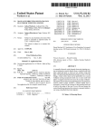
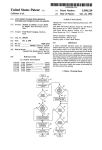
Referring back to FIG. 3, in accordance With the embodi
ment of the present invention, the visual alarm signal is
sWitch signal, the microprocessor generates a test signal on
line 86 to the smoke sensor via chamber push-to-test circuit
generated only during the off periods 97 of the audible alarm
88. The push-to-test signal also generates appropriate sig
nals along line 48 to test the CO sensor and circuit 46.
5
The chamber push-to-test circuit 88 modi?es the output of
are activated one at a time based on an operational sequence
the smoke sensor such that the smoke detector ASIC 54
generates a smoke signal 56 if the smoke sensor 52 is
operating correctly, as is conventional. If the smoke sensor
52 is operating correctly, the microprocessor 22 Will receive
the smoke signal on line 56 and generate a smoke alarm
signal on line 90 to the transducer 24. As discussed
15
stored in the microprocessor control unit 22. The smoke
LEDs 63—65 Were selected to be off during the alarm pulses
92, 94 and 96 to maintain the audibility of the horn trans
ducer 24 by avoiding additional current drain from the LEDs
during the simultaneous operation of the LEDs and the horn
24.
As described previously, the off periods 97 of the audible
alarm signal 89 in the embodiment of the invention illus
20
trated have a duration of approximately 500 ms ?tted
betWeen the alarm pulses having the same 500 ms duration.
In accordance With the invention, the inventor has deter
mined that the activation period for each of the smoke LEDs
63—65 Will be 10 ms, although other durations are clearly
10
previously, upon depression of the push-to-test sWitch 60,
the transducer 24 generates an audible alarm signal.
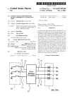
Referring noW to FIG. 3, thereshoWn is the standard
format for an audible smoke alarm signal 89 generated by
the adverse condition detector 18. As illustrated, the smoke
alarm signal 89 has an alarm period 90 that includes three
alarm pulses 92, 94 and 96 each having a pulse duration of
0.5 seconds separated by an off period 97 of 0.5 seconds.
After the third alarm pulse 96 is generated, the temporal
signal has an off period 99 of approximately 1.5 seconds
such that the overall period 90 is 4.0 seconds. After comple
tion of the ?rst alarm period 90, the period is continuously
repeated as long as an adverse condition exists.
25
In addition to generation of the audible alarm signal 89
shoWn in FIG. 3, the adverse condition detector 18 of the
present invention also generates a visual alarm signal to
indicate to the user that smoke has been sensed by the smoke
sensor 52. In accordance With the present invention, the
visual alarm signal is generated to provide a visual indica
tion to the user that visually simulates the actual type of
signal 89. Thus, the smoke LEDs 63—65 are all deactivated
When the audible horn is on during the alarm pulses 92, 94
and 96. During the off periods 97, the smoke LEDs 63—65
possible. Thus, ?fty 10 ms time slots or activation periods
can occur during each 500 ms off period 97. During each of
the ?fty time slots or activation periods, the microprocessor
control unit 22 activates only one of the smoke LEDs 63—65.
Thus, the operational sequence and pattern stored Within the
microprocessor control unit 22 requires 450 locations of
memory. These 450 locations of memory are allocated to the
three smoke LEDs, each having ?fty time slots of operation
during each off period, multiplied by the three off periods
30
that occur during each cycle of the audible alarm signal. A
small sample of the visual alarm operational sequence is set
forth beloW in Table 1.
adverse condition being detected. Speci?cally, in the
embodiment of the invention illustrated, the detector 18
creates a visual alarm signal that simulates the appearance of
a ?ickering ?ame When the smoke sensor 52 is sensing
smoke and the smoke detector ASIC 56 is generating a
TABLE 1
35
smoke detection signal.
In the embodiment of the invention illustrated in FIG. 2,
the detector 18 is able to generate a visual alarm signal that
40
simulates a ?ickering ?ame by sequentially activating and
deactivating a plurality of visual indicators, such as the
smoke LEDs 63, 64 and 65, in a “random” pattern. In the
embodiment of the invention illustrated in FIG. 2, the ?rst
smoke LED 63 is a red LED, the second smoke LED 64 is
Time
Horn
LED 1
LED 2
LED 3
0—0.500
0.510
0.520
0.530
0.540
0.550
0.560
0.570
0.580
ON
OFF
OFF
OFF
OFF
OFF
OFF
OFF
OFF
OFF
ON
OFF
OFF
OFF
ON
OFF
ON
OFF
OFF
OFF
ON
OFF
ON
OFF
OFF
OFF
ON
OFF
OFF
OFF
ON
OFF
OFF
ON
OFF
OFF
OFF
ON
OFF
OFF
OFF
OFF
OFF
OFF
45
an orange LED and the third smoke LED 65 is a yelloW
0.990
1.000—1.5
LED. By sequentially operating the LEDs 63—65, the micro
processor control unit 22 can give the visual appearance of
a ?ickering ?ame When vieWed from beloW the adverse
as an operation sequence such that the LEDs 63—65 can be
As illustrated in Table 1, the horn is operated for the ?rst
500 ms, as illustrated by the alarm pulse 92 in FIG. 3. The
horn is then quiet for the next 500 ms, Which corresponds to
operated to simulate the appearance of a ?ame. It is impor
the ?rst off period 97. During the ?rst off period, the LEDs
condition detector 18. The pattern of operation of the smoke
LEDs 63—65 is stored in the microprocessor control unit 22
50
63—65 are operated as shoWn in Table 1.
tant to note that any actual operational sequence can be
utiliZed While operating Within the scope of the present
invention as long as the operational sequence operates the
55
LEDs 63—65 in a manner that simulates a ?ame.
In the embodiment of the invention illustrated in FIG. 2,
the adverse condition detector 18 can at times be operated by
only the battery 40. Since the detector 18 includes three
separate smoke LEDs 63, 64 and 65, the simultaneous
60
Only a portion of the ?fty time slots are set forth in Table
1, since the actual sequence of operation can be changed
While operating Within the scope of the present invention. It
should be understood that the operational sequence for the
three smoke LEDs 63—65 of the present invention is shoWn
for illustrative purposes only, and should form no part of the
present invention. Instead, it should be understood that a
activation of all three LEDs Would result in excessive LED
“pseudo-random” pattern of operating the three smoke
currents, Which Would cause a reduction in the life of the
LEDs 63—65 is the focus of the sequence and other
sequences can be utiliZed While operating Within the scope
of the present invention.
battery 40. Therefore, in accordance With the present
invention, only one of the smoke LEDs 63—65 Will be
illuminated at a time to minimiZe the amount of LED current
utiliZed to generate the visual alarm signal.
65
As described previously, the microprocessor control unit
22 shoWn in FIG. 2 includes 450 locations of memory
US 6,914,534 B2
10
visible color spectrum by appropriate energiZation of its
allocated to the LED operational sequence. The 450 memory
locations are dictated by the requirements of the audible
alarm signal 89 shoWn in FIG. 3. Presently, smoke alarms
elements. If each of the smoke LEDs 63—65 Were replaced
by a bi-color or tri-color device, the microprocessor control
produced for use in the Canadian market include a different
unit 22 Would be con?gured to “randomly” generate the
type of audible alarm signal that has a four second overall
time period With four horn modulations per second, for a
total of siXteen modulations per cycle. If the visual alarm
multiple colors to create a ?ickering ?ame effect. To do this,
different memory locations Would be allocated in the micro
processor control unit 22 such that the microprocessor
control unit 22 could control the operation of the LEDs
signal is generated only during off periods of the Canadian
accordingly.
alarm signal, there are 16 off periods available, each having
a possibility of eight 10 ms time slots for each of the three
10
separate smoke LEDs 63, 64 and 65. Thus, if the adverse
condition detector is utiliZed in the Canadian market, the
microprocessor control unit 22 requires 384 locations of
memory to create the LED ?ickering effect. It should be
understood that the number of memory locations allocated
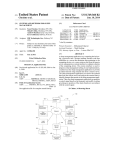
Referring noW to FIG. 7, thereshoWn is a preferred
implementation of the plurality of smoke LEDs 63, 64 and
65 in the detector. As illustrated, each of the LEDs 63—65 is
mounted to a printed circuit board 110 in a side-by-side
relationship. Preferably, the LEDs 63—65 are mounted in a
15
straight line, although other mountings on the circuit board
Within the microprocessor control unit 22 is dependent upon
110 are contemplated as being Within the scope of the
the type of audible alarm signal 89 being generated by the
microprocessor control unit 22.
present invention.
As illustrated, each of the LEDs is positioned betWeen a
Referring noW to FIGS. 4—6, thereshoWn is a portion of
leg 112 of a light pipe 114. The light pipe 114 is a plastic
the visual alarm signal including the sequence of operation
component that is used to direct light from the LEDs to a
of the LEDs 63, 64 and 65 set forth in Table 1 during the ?rst
off period 97 of the audible alarm signal 89 illustrated in
FIG. 3. As illustrated in FIGS. 4—6, the ?rst smoke LED 63
remote location. As illustrated in FIG. 7, the light pipe 114
includes a main body 116 having an outlet end 118 posi
tioned beloW a slot 120 formed in the plastic housing 122 of
the adverse condition detector of the present invention. The
single light pipe 114 directs the light from each of the three
is activated for the ?rst 10 ms activation periods, as illus
trated by pulse 100. While the ?rst smoke LED is being
25
operated, the remaining LEDs 64 and 65 are off, as illus
trated in FIGS. 5 and 6.
After the end of the ?rst activation period, the pulse 100
terminates and the second LED 64 is activated, as illustrated
LEDs 63, 64 and 65 to the common slot 120 such that the
light emitted by the LEDs can be vieWed from the eXterior
by pulse 102. During the second activation period, only the
of the housing 122. The actual physical con?guration of the
light pipe 114 forms no part of the present invention eXcept
that the light pipe 114 alloWs the light from the three LEDs
second smoke LED 64 is activated While the smoke LEDs 63
63, 64 and 65 to be vieWed through the same slot 120.
and 65 are off.
During the neXt activation period, the third LED 64 is
activated, as illustrated by pulse 104, While the ?rst and
second smoke LEDs 63 and 64 are turned off. This process
Although the preferred embodiment of the invention is
described as having a light pipe 114 that can be vieWed
35
is repeated for each activation period until the expiration of
the off period 97 of the audible alarm signal 89. During the
neXt off period, another stored operational sequence is
initiated to create the ?ickering pattern to simulate a ?ame.
As can be understood in FIGS. 4—6, only one of the smoke
40
While operating Within the scope of the present invention.
Further, if the poWer supply is able to generate an adequate
amount of current, the visual alarm signal could be gener
ated during the entire duration of the audible alarm signal
89, not just the off period 97 as described in the present
invention.
In the embodiment of the invention illustrated in FIG. 2,
the smoke LEDs 63—65 each have a different color, prefer
the housing could have a transparent, translucent or thin
section that alloWs the light from the visual indicators to be
seen from beneath the detector. Alternatively, it is contem
plated that the light generated by the visual indicators could
be projected onto the ceiling and vieWed from beloW by the
user. In any event, the visual alarm signal being generated by
LEDs 63—65 is activated at any time during the generation
of the visual alarm signal. Although the requirement that
only one of the smoke LEDs 63—65 be activated at a given
time to conserve battery poWer, it should be understood that
if poWer consumption is not an issue, more than one of the
smoke LEDs 63—64 could be activated at the same time
through a slot 120 formed in the housing 122, it should be
understood that the speci?c manner in Which the light
generated by the visual indicators is vieWed forms no part of
the present invention. For eXample, it is contemplated that
45
the detector must be vieWable by the user such that the user
can visually correlate the alarm signal With a type of adverse
condition being detected.
In the present invention, the colors of the smoke LEDs
63—65 are selected such that When the LEDs 63—65 are
operated by the microprocessor control unit 22, the smoke
LEDs 63—65 Will simulate the appearance of a ?ame. Thus,
the home occupant Will be able to simply look at the adverse
55
condition detector and see the ?ickering “?ame” created by
the smoke LEDs 63—65 and immediately be informed of the
type of adverse condition being detected.
ably red, orange and yelloW. HoWever, it is contemplated by
Although the present invention is particularly suited for
the inventor that each of the smoke LEDs 63—65 could be
replaced by a bi-color or tri-color LED that is capable of
generating more than one color of light. A bi-color device
can produce tWo single colors and multiple shades of color
betWeen the tWo main colors, for instance a red/green LED
use With a smoke detector, it is contemplated that the smoke
LEDs 63—65 could be replaced by other types of visual
indicators, such as an LCD color screen or other visual
can produce yelloW light if both LED elements are energiZed
simultaneously. By appropriately modulating the currents in
each element, the spectrum of color can range smoothly
from red, through orange, to yelloW, through yelloW-green,
and ?nally to green, including an near-in?nite number of
intermediate shades. A tri-color LED can emulate the entire
65
device While operating Within the scope of the present
invention. It is important that the microprocessor control
unit 22 be able to generate a visual alarm signal that alloWs
the home occupant to quickly determine the type of adverse
condition being detected Without having to recall the mean
ing of the speci?c audible pattern of the audible alarm
signal. Additionally, the adverse condition detector of the
present invention alloWs the user to identify the visual alarm
US 6,914,534 B2
11
12
signal With the type of adverse condition being detected
12. A method of operating an adverse condition detection
Without having to understand a spoken command from the
apparatus to generate a visual alarm signal that visually
stimulates the type of adverse condition detected by the
apparatus, the method comprising the steps of:
detector, as Was the case in prior art detectors.
Various alternatives and embodiments are contemplated
as being Within the scope of the folloWing claims particu
larly pointing out and distinctly claiming the subject matter
providing an adverse condition sensor operable to gener
ate a detection signal upon sensing the presence of the
regarded as the invention.
I claim:
1. An adverse condition detection apparatus operable to
receiving the detection signal in a control unit of the
detect an adverse condition and generate a visual alarm
signal to indicate the presence of the adverse condition, the
adverse condition;
apparatus;
10
apparatus comprising:
an adverse condition sensor operable to detect the adverse
selectively activating and deactivating the visual indica
condition and generate a detection signal;
tors in a simulation pattern to create the visual alarm
a control unit coupled to the adverse condition sensor for
signal, Wherein the simulation pattern visually simu
lates the type of adverse condition being detected.
receiving the detection signal, the control unit being
operable to control the generation of both the visual
alarm signal and an audible alarm signal during the
13. The method of claim 12 Wherein the adverse condition
generation of the detection signal;
sensor is a smoke sensor.
14. The method of claim 13 Wherein the visual indicators
comprise a red LED, an orange LED, and a yelloW LED.
an audible indicator coupled to the control unit, Wherein
the control unit activates the audible indicator to gen
erate an audible alarm signal upon detection of the
15. The method of claim 12 further comprising the step of
storing an operational sequence in the control unit, the
adverse condition; and
operational sequence de?ning the sequence of operation of
a visual indicator coupled to the control unit, the visual
indicator being operable to generate the visual alarm
signal upon detection of the adverse condition, Wherein
providing at least tWo visual indicators coupled to the
control unit, the combination of visual indicators being
selectively operable to emit light of at least tWo differ
ent colors;
25
the visual indicators by the control unit.
16. The method of claim 15 Wherein the control unit
the visual indicator includes at least tWo LED’s that
activates only one of the visual indicators at a time.
each emit light of a different color, the LED’s being
17. The method of claim 16 Wherein each of the visual
indicators is activated for an activation period, Wherein the
selectively operated such that the visual alarm signal
visually simulates the type of adverse condition being
visual alarm signal includes a plurality of sequential acti
vation periods during Which only one of the visual indicators
is activated.
18. The method of claim 13 Wherein the operational
sequence controls the operation of the visual indicators to
detected.
2. The apparatus of claim 1 wherein the visual indicator
is a color LCD screen.
3. The apparatus of claim 1 Wherein each of the LED’s is
a multi-color LED.
35
4. The apparatus of claim 1 Wherein only one of the visual
indicators is operated at a time by the control unit.
5. The apparatus of claim 4 Wherein each of the visual
indicators are selectively operated by the control unit for
individual activation periods, Wherein the visual alarm sig
nal includes a plurality of sequential activation periods
during Which only one of the visual indicators is operated at
40
condition;
45
are selectively operated by the control unit in a pattern to
visually simulate the appearance of a ?ame.
8. The apparatus of claim 1 Wherein the audible alarm
20. The method of claim 19 further comprising the step of
storing an operational sequence in the control unit, the
an off period, Wherein the control unit operates the visual
indicator only during the off periods of the alarm signal.
operational sequence de?ning the sequence of operation of
55
period betWeen the alarm pulses of the alarm signal such that
multiple activation periods occur during each off period of
the audible alarm signal.
10. The apparatus of claim 1 Wherein the control unit
includes a stored operational sequence for the activation of
the visual indicators, Wherein the visual indicators are selec
tively activated based upon the stored operational sequence.
11. The apparatus of claim 1 Wherein the adverse condi
tion detection apparatus includes a housing for enclosing the
adverse condition sensor, the control unit and the visual 65
indicators, Wherein the visual indicators can be seen from
the exterior of the housing.
alarm signal upon receipt of the detection signal by the
control unit; and
selectively activating and deactivating at least tWo visual
indicators in a pattern that visually simulates the type of
adverse condition being sensed, Wherein the combina
tion of the visual indicators are operable to generate at
least tWo different colors of light.
signal includes a plurality of alarm pulses each separated by
9. The apparatus of claim 8 Wherein each of the visual
indicators is operated by the control unit for an activation
period, Wherein the activation period is shorter than the off
19. A method of operating an adverse condition detection
apparatus having an adverse condition sensor operable to
detect an adverse condition, the method comprising the steps
of:
providing a control unit coupled to the sensor to receive
a detection signal upon the sensor detecting the adverse
activating an audible indicator to generate an audible
a time.
6. The apparatus of claim 1 Wherein the visual indicators
comprise a yelloW LED, an orange LED and a red LED.
7. The apparatus of claim 6 Wherein the visual indicators
simulate the appearance of a ?ame.
the visual indicators by the control unit.
21. The method of claim 19 Wherein each of the visual
indicators is operable by the control unit for an activation
period, Wherein the operational sequence includes a stored
sequence of activation periods.
22. The method of claim 20 Wherein only one of the visual
indicators is operable at a time by the control unit.
23. The method of claim 2 Wherein the audible alarm
signal includes a series of alarm pulses each separated by an
off period, Wherein the visual indicators are activated by the
control unit only during the off period of the audible alarm
signal.