1
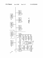
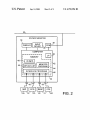
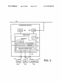
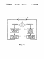
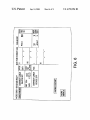
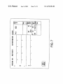
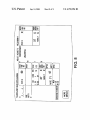
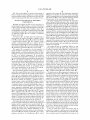
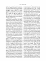
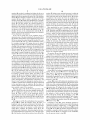
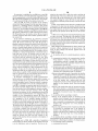
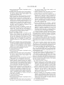
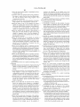
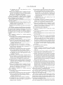
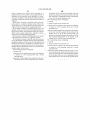
US006792396B2
(12) United States Patent
(10) Patent N0.:
Inda et al.
(54)
(75)
US 6,792,396 B2
(45) Date of Patent:
INTERFACE DEVICE AND METHOD FOR A
W0
WO 00/25284 A2
MONITORING NETWORK
W0
WO 00/42911
7/2000
W0
WO 01/43631 A1
6/2001
W0
W0 02/064032 A2
8/2002
Inventors: Allan G. Inda, Milwaukee, WI (US);
Daniel J. NOWicki, Cedarburg, WI
(US); Michael .I. Horvath, Port
_
Ryzin, PeWaukee, WI (Us)
_
_
Vargas, Home—l3ased Momtormg of Cardiac Patents, Jun.
1998, IEEE Article, vol.: 4793, pp. 133—136.*
Sukuvaara et al., “Intelligent Patient Monitor— Its Function
and User Interface”, Jul. 1992, IEEE Article, vol.:2485, pag
(73) AssigneeZ GE Medical Systems Information
Technologies, Inc» M?Waukee> WI
Notice:
5/2000
OTHER PUBLICATIONS
Washington, WI (US); Patrick A. Van
( >l< )
Sep. 14, 2004
(US)
s 373—376.*
Subject to any disclaimer, the term of this
“OctanetTM
patent is extended or adjusted under 35
(81—page product manual); 418264—003, Revision B; GE
U_S_C_ 154(k)) by 69 days_
Marquette Medical Systems, Inc. (Jan. 14, 2000).
“Octacomm Connectivity Device Operator/Service
Manual”, (155—page product manual); SoftWare Versions 1
(21) Appl, N()_j 10/109,542
_
Connectivity
Device
Service' ' Manual”;
and 2; 418264—001, Revision C; GE Marquette Medical
(22) Flled:
Mar‘ 28’ 2002
Systems, Inc. (Jan. 8, 1999).
(65)
Prior Publication Data
Search Report, GB 03064771, Jul. 10, 2003.
US 2003/0187618 A1 Oct. 2, 2003
_
_
* cited by eXammer
(51)
Int. Cl.7 ............................................... .. G06F 11/00
52
US. Cl. ......................... .. 702/188; 702/19; 702/32;
( )
702/121; 702/188; 340/539.22,
340/870.06;
_
_
(58)
Field of Search ............................ .. 702/19, 21, 32,
.
.
pmlmy Ex”m"7e’—Ma.rC 5" Hoff
Assistant Examzner—El1as Desta
375/220’ 600/301’ 455/557
(74) Attorne A em or Firm—Audrus Sceales Starke &
SaWaH
702/33, 121, 122, 182, 183, 186, 187, 188,
FOR 103, 104, 115, 119, 134, 135, 170,
171; 340/870.06, 870.27, 573.3, 539.22;
y’
g
(57)
455/657; 375/220; 600/305, 301; 128/846
’
’
’
ABSTRACT
An interface device receives data from a plurality of sensors
and transmits the data over a communication network to one
(56)
References Cited
or more of a plurality of monitors. The interface device is
capable of operating in both a peripheral mode of operation
US. PATENT DOCUMENTS
5 465 082 A
and a stand-alone mode of operation for the plurality of
* 11/1995 Chaco ~~~~~~~~~~~~~~ " 340/8255,‘
monitors. In another embodiment, a monitor is connected to
5:867:821 A *
2/1999 Ballantyne et aL __________ __ 705/2
a plurality of interface devices by Way of a communication
6,440,071 B1
8/2002 slayton et a1_
netWork. A separate visible physical communication link or
1/2003 Dalal ........................ .. 607/32
6/2003 Nielsen et a1. ............ .. 600/513
other identi?cation link is used to visually identify Which of
the interface devices is serving as a peripheral device for the
2003/0003127 A1 *
2003/0120164 A1 *
monitor.
FOREIGN PATENT DOCUMENTS
W0
WO 92/04806 A1
3/1992
36 Claims, 8 Drawing Sheets
1
1O
\
2B
'
l 24
INTERFACE
DEVICE
|
CENTRAL
MONITOR
I
l
:
26
PATIENT
26
“'1 MONITOR
PATIENT
MONITOR
I
I_____.-__|__l
l
20\
12
1s
25
22
INTERFACE
PATIENT
DEVICE
1B3
27
[ DEVICE
148
/
2a
14
NSF
14b
15
14c
18b
RESP
18c
14d
UROMETER
18
14
INTERFACE
MONITOR
CO2
INTERFACE
DEVICE
2s
INTERFACE
DEVICE
:5
U.S. Patent
Sep. 14, 2004
Sheet 3 of 8
US 6,792,396 B2
201
INTERFACE DEVICE
LEDs ~64
66-
COM
COMPUTER
'- ______ __-‘
I
MEMORY
.L
76’|
p L
l
‘1
—----1
IDINFO
PHD
|
PROGRAM
78x2 DEVICE LIST
|
MEMORY \bqz
I
:
68
|
SENSOR INTERFACES
l
l “74
___....__.r.__2,_._.__
(
62
T__I
18
“ r’
SPO2
18a )
|_
F1
?sokLj
VENT
Y18b
UROMETER
z184:
18
/
FIG 3
-
U.S. Patent
Sep. 14, 2004
Sheet 4 of 8
US 6,792,396 B2
91
,_J
+ ACQUIRE DATA p
PERIPHERAL
MODE
TRANSMIT DATA 32
TO SELECTED
MONITOR
STAND-ALONE
94w TRANSMIT
DATA TO
MULTIPLE
l
MONITORS
II
DISPLAY DATA f9?)
AT SELECTED
MONITOR
________l
95.\ DISPLAY DATA
AT MULTIPLE
MONITORS
l_____.v
FIG. 4
U.S. Patent
Sep. 14, 2004
Sheet 5 of 8
US 6,792,396 B2
1,
100
J1o2
INTERFACE DEVICE
REQUESTS TO
ASSOCIATE
COM LINK
PRESENT 7
/
NO
_,1os
MONITOR VALIDATES
PACKET AND SENDS ACK
TO INTERFACE DEvICE
r110
SET LED TO
PACKET VALID ?
FLASHING YELLOW
SET LED TO SOLID YELLOW “1 12
114
MONITOR ON
NETWORK '2
N0
_,116
SET LED To
SOLID GREEN
'
INTERFACE DEVICE
" SLEEPS TWO SECONDS
“
11s
FlG- 5
U.S. Patent
Sep. 14, 2004
Sheet 7 of 8
US 6,792,396 B2
US 6,792,396 B2
1
2
INTERFACE DEVICE AND METHOD FOR A
MONITORING NETWORK
interface, a microprocessor, and a memory. The communi
cation interface is adapted to connect the interface device to
a communication netWork to transmit data acquired by the
interface device using a plurality of sensors over the com
FIELD OF THE INVENTION
munication netWork. The memory is programmed to provide
the interface device With a peripheral mode of operation and
a stand-alone mode of operation. In the peripheral mode of
operation, the interface device operates as a peripheral
This invention relates to monitoring systems and, in
particular, relates to interface devices and methods used in
a monitoring netWork to acquire data from a system under
test.
10
BACKGROUND OF THE INVENTION
alone device for multiple ones of the plurality of monitors.
In particular, in the stand-alone mode of operation, the
Monitoring netWorks and devices are knoWn for moni
interface device operates as a stand-alone device available to
transmit the data from the sensors to multiple ones of the
toring systems under test. For example, in medical
applications, patient monitors are knoWn for monitoring
patients. A typical patient monitor includes a display, one or
more operator input devices, one or more input ports for
connecting the monitor to sensors that acquire data from the
patient, and a microprocessor or other signal processor for
15
tem comprises a communication netWork, a sensor, an
A large variety of sensors exist that may be used for data
acquisition. For example, in medical applications, it may be
the plurality of monitors is coupled to the communication
desirable to receive data from sensors such as a carbon
dioxide (CO2) sensor, a ventilator sensor, a urometer sensor,
a pulse oximetry (SPO2) sensor, an ECG sensor, a respira
netWork. The interface device has a peripheral mode of
operation and a stand-alone mode of operation. The interface
25 device operates as a peripheral device for a selected one of
the plurality of monitors in the peripheral mode of operation,
and operates as a stand-alone device available to transmit the
types, a Wide range of speci?c sensors exist that are avail
data to each of the plurality of monitors in the stand-alone
able from different manufacturers, and it is desirable to be
able to provide health care facilities With the option of
connecting patient monitors to a variety of different sensors
mode of operation.
According to another preferred aspect, a monitoring sys
available from different sensor manufacturers.
Interface devices are sometimes used to increase the
number and/or variety of sensors that can be used to acquire
data for a monitoring device. Often, one or more such 35
interface devices are connected to a communication netWork
along With one or more monitoring devices. Aneed exists for
an interface device that can operate in a variety of modes of
operation. For example, in some situations, it is desirable to
have an interface device that operates in a stand-alone mode
40
of operation, e.g., by transmitting data over a communica
tion netWork to a variety of monitoring devices. This alloWs
tem comprises a communication netWork, a plurality of
sensors, a monitor, a plurality of interface devices, and an
identi?cation link. The plurality of sensors are capable of
acquiring data from a plurality of systems under test. The
monitor has a display and is coupled to the communication
netWork. The plurality of interface devices are coupled to
respective ones of the plurality of sensors to receive the data
from the systems under test. The plurality of interface
devices are also coupled to the communication netWork. A
selected one of the plurality of interface devices operates as
a peripheral device for the monitor. The identi?cation link
provides a separate physical connection betWeen the monitor
the data from the sensors to be made available at any
monitoring device that Wishes to vieW the data. In other
instances, it is desirable to have an interface device that
plurality of monitors by Way of the communication netWork.
According to another preferred aspect, a monitoring sys
interface device, and a plurality of monitors. The sensor is
capable of acquiring data from a system under test. The
interface device is coupled to the sensor to receive the data
from the system under test. The interface device and each of
processing the data acquired from the patient.
tion sensor, an invasive or non-invasive blood pressure
sensor, and so on. Within each of these different sensor
device for one of a plurality of monitors. In the stand-alone
mode of operation, the interface device operates as a stand
45
serves as a peripheral device for a monitoring device. For
example, it may be desirable for the interface device to
operate from an operator’s perspective as if the interface
device is directly connected to the monitoring device, or in
some other manner Which results in the operator perceiving
the monitoring device as being more closely associated With
the particular interface device than With other interface
and the selected one of the plurality of interface devices to
thereby provide a visual indication Which one of the plural
ity of interface devices is operating as the peripheral device
for the monitor.
BRIEF DESCRIPTION OF THE DRAWINGS
FIG. 1 is a block diagram of a patient monitoring system
according to a preferred embodiment;
FIG. 2 is a block diagram shoWing a patient monitor of the
system of FIG. 1 in greater detail;
devices on the communication netWork.
FIG. 3 is a block diagram shoWing an interface device of
Additionally, such interface devices and monitoring
device are often connected to a communication netWork 55
along With other interface devices and monitoring devices.
the system of FIG. 1 in greater detail;
FIG. 4 is a ?oWchart shoWing the operation of the system
When establishing a netWork connection betWeen a particu
of FIG. 1 in either a stand-alone mode of operation or a
lar patient monitoring device and a particular interface
peripheral mode of operation;
device, a need exists for a Way to ensure that the correct tWo
FIG. 5 is another ?oWchart shoWing operation of an
devices are connected together and to make connecting the
tWo devices together as easy for the operator as possible.
interface device to associate With a monitor in the system of
FIG. 1;
A monitoring system and method that meets one or more
of these needs Would be highly desirable.
BRIEF SUMMARY OF THE INVENTION
According to a ?rst preferred embodiment, an interface
device for a monitoring system comprises a communication
65
FIG. 6 is a screen display of a monitor in the system of
FIG. 1 in Which the monitor displays data from an interface
device alongside the monitor’s oWn data;
FIG. 7 is a screen display of a monitor in the system of
FIG. 1 in Which the monitor displays data from an interface
device merged along With its oWn data; and
US 6,792,396 B2
4
3
operation of the monitor 12. The identi?cation information
48 includes an identi?er by Which the monitor 12 is iden
FIG. 8 is a screen display of a monitor in the system of
FIG. 1 in Which the monitor displays its oWn data alongside
data from another monitor, and With the data from the other
monitor being merged With data from an interface device.
DETAILED DESCRIPTION OF PREFERRED
EMBODIMENTS
Referring noW initially to FIGS. 1—3, an overvieW of a
monitoring system 10 according to a preferred embodiment
is shoWn. The monitoring system 10 comprises a monitor 12,
10
a ?rst plurality of sensors 14, an interface device 16, a
second plurality of sensors 18, a communication netWork 20,
an identi?cation adapter 22, a central monitor 24, a plurality
of additional monitors 26, and a plurality of additional
interface devices 28.
As shoWn in FIG. 2, Which shoWs the monitor 12 in
15
ti?ed for communication on the communication netWork 20.
The device list 50 is a list of devices (monitors, interface
devices) active on the communication netWork 20.
The interface device 16 is connected to the second plu
rality of sensors 18. With reference to FIG. 3, Which shoWs
the interface device 16 in greater detail, the interface device
16 includes a plurality of input ports 60, a computer 62, a
plurality of indicators 64 such as LEDs, and a communica
tion interface 66. The input ports 60 are connected to the
sensors 18 and receive the data acquired by the sensors from
the patient 29. The communication interface 66 connects the
interface device to the communication netWork 20 to trans
mit the data from the sensors 18 over the communication
netWork 20. The computer further includes a microprocessor
68 and a memory 70. The memory 70 includes memory that
greater detail, the monitor 12 includes a plurality of input
ports 30, a computer 32, a display 34, an input device 36 and
stores programs executed by the microprocessor 68 for
operation of the interface device, such as program memory
a communication interface 38. The computer further
includes a microprocessor 40 and a memory 42. The
memory 42 is programmed and stores such things as one or
72 and sensor interface memory 74, as Well as memory that
stores other information such as identi?cation information
76 and a device list 78.
The sensors 18 may be completely different or may
more monitor programs 44, one or more interface programs
46, identi?cation information 48, and a device list 50.
The monitor 12 is connected to the ?rst plurality of
sensors 14. These connections may be made by analog or
overlap With the sensors 14. Again, these connections may
25
be made by analog or digital (parallel or serial) communi
hardWired or Wireless connection of the sensor to the moni
cation links, by direct connection of the sensor to the
interface device 16, or by another arrangement. The sensors
18 are preferably connected to the interface device 16 by
tor 12, or by another arrangement. In the preferred
Way of identical input ports 60 (e.g., RS-232 ports) disposed
embodiment, the sensors 14 are connected to the monitor 12
on the interface device 16, Which provide a standard com
munication interface for connecting sensors from various
manufacturers to the interface device 16. The sensors 18
may include a variety of different types of sensors that
acquire different types of data as described above in con
digital (parallel or serial) communication links, by direct
by Way of input ports 30. In one embodiment, the input ports
30 are each uniquely con?gured for a particular type of
sensor, such that a given input port 30 may only be used With
a particular type of sensor. Alternatively, the input ports may
be identical ports, such as RS-232 ports, to provide a
standard communication interface for connecting sensors
from various manufacturers to the monitor 12. A combina
tion of these tWo approaches may also be used.
The sensors 14 may include a variety of different types of
sensors that acquire different types of data. In the preferred
embodiment, the monitor 12 is a portable patient monitor
35
embodiment, the sensors 18 are used by the interface device
16 to acquire physiological data from the patient 29. In FIG.
1, the sensors 18 are shoWn as including an SPO2 sensor
18a, a ventilator sensor 18b, and a urometer sensor 18c.
40
The interface device 16 is programmed to support each of
the different types of sensors 18 to Which it is connected. To
and is used to continuously monitor parameters from a
patient 29. In this embodiment, the sensors 14 are used by
this end, the interface device includes the interface programs
74 Which are useable to interpret and process the data
acquired by the sensors 18. The sensors 18 each include
the monitor 12 to acquire physiological data from the patient
29 and may include, for example, a ventilator sensor, a
urometer sensor, a pulse oximetry (SPO2) sensor, a carbon
junction With the sensors 14. In the patient monitoring
45
memory (not shoWn) that stores identi?cation information
(e.g., device type) for the sensor 18. When one of the sensors
dioxide (CO2) sensor, an electrocardiograph (ECG) sensor,
18 is initially connected to the interface device 16, this
a respiration sensor, an invasive blood pressure sensor, a
information is transmitted to the interface device 16 so that
the interface device 16 can determine the type of sensor to
Which it is connected. Based on this information, the inter
face device 16 uses a particular interface program 74 to
non-invasive blood pressure (NBP) sensor, cardiac output
sensor, impedance cardiography sensor, electroencephalo
graph (EEG) sensor and so on. In FIG. 1, the sensors 14 are
shoWn as including an NBP sensor 14a, and ECG sensor
14b, a respiration sensor 14c and a CO2 sensor 14d. The
monitor 12 is programmed to support each of the different
types of sensors 14 to Which it is connected. To this end, the
interpret and process the data from the particular sensor 18.
In this regard, it may be noted that the interface device 16
may be used to serve as a universal interface device for a
55
monitor 12 includes the interface programs 46 Which are
variety of different types of sensors. In other Words, When a
decision is made to support a neW type of sensor, interface
softWare for the neW type of sensor is developed and
useable to interpret and process the data acquired the dif
ferent sensors Which are supported by the monitor 12.
The display 34 and the input device 36 of the monitor 12
provide an operator interface by Which operator inputs are
acquired and data acquired by the sensors 14 and 18 is
displayed to the operator. The communication interface 38
connects the monitor 12 to the communication netWork 20,
alloWing the monitor 12 to transmit information to and
programmed into the interface device 16. Any type of
monitor or other device that is connected to the communi
cation netWork 20 then has access to the data acquired by the
neW type of sensor by Way of the interface device 16. There
is no need to develop interface softWare for each of these
different types of monitors individually.
It may be noted that in some cases sensors may be
tion netWork 20. The monitor program 44 is one or more
connected to a monitor or interface device only indirectly
and a certain amount of preprocessing may occur before data
programs executed by the microprocessor 40 to control
from a particular sensor is transmitted to the monitor or the
receive information from other devices on the communica
65
US 6,792,396 B2
5
6
interface device. For example, in connection With the ven
tilator sensor 18b, this sensor is likely to be provided as part
of or attached to a ventilator system having its oWn computer
system and an output port. The output port of the ventilator
system may be connected to an input port 60 of the interface
device 16, and data may be transferred to the interface
device 16 via the connection made betWeen these tWo ports.
The interface device 16 is therefore connected to the sensor
there is little opportunity for confusion on the operator’s part
as to Which tWo devices are connected together. This avoids
a situation in Which the operator is under a mistaken
impression that the monitor 12 is con?gured to receive data
for one patient from one interface device, When in fact the
monitor 12 is actually con?gured to receive data for a
different patient from a different interface device. Of course,
it Would also be possible to transmit the data acquired by the
18b by Way of the ventilator computer system, and the data
from the ventilator sensor 18b is made available to the
1O
interface device 16 by the ventilator computer system, as
opposed to by the sensor 18b itself directly. Similar arrange
ments may be used for other devices such as respirators. In
other cases, particular sensors may be directly connected to
the monitors and interface devices.
The communication netWork 20 connects the patient
The identi?cation adapter 22 includes memory (not
shoWn) that stores device type information that is transmit
ted to the interface device 16 and that is used by the interface
device 16 to distinguish the identi?cation adapter 22 from
15 some other type of device, such as a sensor. This is akin to
the device type information stored and transmitted by the
monitor 12, the interface device 16, the central monitor 24,
the patient monitors 26 and the interface devices 28. The
sensors 18. This alloWs the interface device 16 to recogniZe
that it is connected to an identi?cation adapter (and thus, by
communication netWork 20 may be a hardWired or Wireless
netWork and may be a local area netWork, metropolitan area
netWork, or Wide area netWork such as the Internet. In the
Way of the identi?cation adapter, to a patient monitor) as
opposed to some other type of device, such as a sensor.
Referring noW also to FIG. 4, an overvieW of the opera
embodiment of FIG. 1, the communication netWork is a
hospital monitoring netWork or other patient monitoring
netWork. The patient monitors 12, 26 and interface devices
16, 28 may be located throughout different rooms of the
sensors 18 by Way of the dedicated communication link 25
instead of by Way of the communication netWork 20.
25
healthcare facility. The monitors 26 may be the same or
tion of the system 10 is illustrated. The interface device 16
has tWo modes of operation, namely, a peripheral mode of
operation and a stand-alone mode of operation.
In the peripheral mode of operation, the interface device
similar in construction and operation to the monitor 12, and
16 operates as a peripheral device for one of the monitors 12,
the interface devices 28 may be the same or similar in
26. By Way of eXample, it is assumed herein that the
construction and operation to the interface device 16. The
interface device 16 is con?gured to operate as a peripheral
patient monitors 26 and the interface devices 28 are con
for the monitor 12, although the interface device 16 could
nected to additional sensors that acquire physiological data
just as easily be con?gured at other times to operate as a
peripheral for one of the other patient monitors 26. In FIG.
from other patients. For simplicity, the additional sensors
4, at step 91, data is acquired from the patient 29 using the
and additional patients are not shoWn in FIG. 1. Other types
sensors 18 connected to the interface device 16. Assuming
of monitors or interface devices may also be used. For
eXample, one of the monitors 26 may be a clinical informa 35 the interface device 16 is operating as a peripheral device for
the monitor 12, then the data is transmitted from the inter
tion system, Which is in essence a device that monitors and
face device 16 to the monitor 12 at step 92. At step 93, the
stores data transmitted on the communication netWork 20.
Other non-monitoring, non-data acquiring devices may also
be connected to the netWork 20, although these devices are
not shoWn in FIG. 1.
40
The identi?cation adapter 22 is disposed betWeen the
monitor 12 and the interface device 16. Preferably, the
identi?cation adapter 22 is embedded in an electrical cable
27 Which forms a dedicated communication link 25 betWeen
the monitor 12 and the interface device 16. The dedicated
data is displayed by the monitor 12.
In one embodiment, in the peripheral mode of operation,
the data acquired by the interface device 16 is available to
remaining ones of the plurality of monitors 26 only through
the monitor 12. Thus, the system 10 may be con?gured such
that data acquired by any of the monitors 12 and 26 may be
displayed at any of the other monitors 12 and 26. This alloWs
data acquired from one patient to be vieWed by a physician
Without the physician necessarily having to be at the
patient’s bedside. In the peripheral mode of operation, the
data acquired by the interface device 16 is available to the
monitors 26 along With the data from the monitor 12.
HoWever, the monitors 26 are not permitted to directly
access the data acquired by the interface device 16; rather,
communication link 25 is separate from the communication
netWork 20 and provides a direct connection betWeen the
monitor 12 and the interface device 16. In the preferred
embodiment, the cable 27 connects to the monitor 12 by Way
of an open one of the input ports 30 used to connect the
monitor 12 to the sensors 14, and connects to the interface
device 16 by Way of an open one of the input ports 60 used
access to the data acquired by the interface device 16 is
to connect the interface device 16 to the sensors 18. The
granted through the monitor 12. Thus, When the interface
cable 27 is preferably bi-directional, so that either end may
be coupled to either the monitor 12 or the interface device
16.
55
device 16 is in the peripheral mode of operation, access to
the data acquired by the interface device 16 is obtained in a
manner Which is substantially the same as the manner in
Which access is obtained to the data acquired by the monitor
In one embodiment, data acquired by the interface device
16 using the sensors 18 is transmitted to the monitor 12 by
12. Data acquired by the interface device 16 using the
sensors 18 is merged With data acquired by the monitor 12
using the sensors 14. From an operator interface perspective,
Way of the communication netWork 20 and not the dedicated
communication link 25. Alternatively, if the communication
link 25 has suf?cient bandWidth, data may be transmitted by
Way of the communication link 25. In this embodiment, the
data from the interface device 16 is vieWed at one of the
monitors 26 by vieWing the data acquired by the monitor 12,
purpose of the cable 27 is limited to providing a reliable Way
and little or no differentiation exists betWeen data acquired
of determining Which tWo devices (i.e., Which interface
device and Which patient monitor) are connected together.
by the interface device 16 and data acquired by the monitor
Because the operator can see a physical, hardWired connec
12. Of course, other con?gurations are also possible.
Additionally, the monitors 26 each maintain a list 50 of
tion betWeen the monitor 12 and the interface device 16,
interface devices 28 on the communication netWork 20. The
65
US 6,792,396 B2
7
8
monitors 26 can then be con?gured to display this list to an
monitor 12 initiate an auto-association process in Which the
interface device 16 and the monitor 12 establish communi
cation With each other and the interface device 16 becomes
a peripheral of the monitor 12. From the standpoint of a
operator (in response to the reception of appropriate operator
inputs), such that an operator may select one of the interface
devices 28. For example, an operator at one of the operator
monitors 26 may Wish to select a particular one of the
interface devices 28, adjust alarm thresholds for a particular
one of the parameters monitored by the selected interface
device 28, and then monitor the selected parameter to
thereby be alerted When the parameter exceeds the alarm
threshold. In the preferred embodiment, When the interface
device 16 is in the peripheral mode of operation, and When
human operator, the operator connects the interface device
16 and the monitor 12 With the cable 27, and this initiates an
auto-detect sequence Wherein the interface device 16 and the
monitor 12 detect the presence of the cable 27 and the
interface device 16 enters the peripheral mode of operation.
10
an operator of one of the monitors 26 displays a list of the
interface devices on the communication netWork 20, the
interface device 16 is not included among the list of interface
devices displayed to the operator.
It may also be noted that, in the peripheral mode of
operation, some of the data transmitted to the monitor 12 by
the interface device 16 may not be displayed by the monitor
or 26. Preferably, step 102 is implemented by the interface
15
For example, intravenous (IV) pump data may be passed
through the monitor 12 to a clinical information system for
charting. Other parameters unknoWn to the monitor 12 may
be passed through as Well. For example, if a particular sensor
25
interface device 16, the data from the particular sensor 18
may simply be passed through the monitor 12 to the other
monitors 26 on the rest of the communication netWork 20.
number of the interface device 16. This is advantageous in
that the unit name and bed number of the monitor 12 can be
nication netWork 20, depending on Which monitors 12, 26
are con?gured to receive such data. As previously noted, in
35
40
At step 104, if the dedicated communication link 25 is not
present, then the process 100 returns to step 102. On the
other hand, if the dedicated communication link 25 is
present at step 104, then the identi?cation information is
successfully transmitted by Way of the dedicated commu
monitors 12, 26 may be con?gured to display data from the
interface device 16 and to silence alarms, adjust alarm
threshold values, initiate graph generating functions, change
patient demographic and identi?cation information, and
automatically con?gured to match that of a location Within
the facility by Way of the data sent from the interface device
16 via the dedicated communication link 25. In this
example, the unit name and bed number of the interface
device 16 pre-con?gured such that it matches the physical
location of the interface device 16 With the facility, such as
a room number and bed location.
the peripheral mode of operation. When the interface device
16 is in the stand-alone mode of operation, the interface
device 16 appears on this list for each of the monitors 12, 26.
In response to suitable operator inputs, any subset of the
the interface device 16 is available to enter the peripheral
mode of operation. The identi?cation information may
include the unit name, bed number and IP address of the
interface device 16. Sending the unit name and bed number
is advantageous if the monitor 12 is a portable monitor
Which is susceptible to being moved from location to
location Within a facility. The monitor 12 may then further
prompt the operator to con?rm the unit name of the interface
device 16, to provide further assurance that the correct tWo
devices are connected together.
The monitor 12 may also change its oWn unit name and
bed number to be similar to that of the unit name and bed
In the stand-alone mode of operation, the interface device
16 operates as a stand-alone device for the monitors 12, 26.
The interface device 16 is available to transmit data directly
to any or all of the monitors 12, 26 by Way of the commu
one embodiment, each of the monitors 12, 26 maintains a list
of interface devices 16, 28 Which are present on the com
munication netWork 20 and Which are available to operate in
device 16 Which attempts to transmit identi?cation informa
tion (or a “packet”) on the dedicated communication link 25
at periodic intervals. This transmission provides an indica
tion to any listening device (particularly, the monitor 12) that
12 but may instead be passed through the monitor 12 to one
of the monitors 26, such as a clinical information system.
18 is not supported by the monitor 12 but is supported by the
More speci?cally, by Way of example, at step 102, the
interface device 16 requests to associate With a monitor 12
nication link 25 to the monitor 12. The process 100 then
others. It may be noted that although the interface device is
proceeds to step 106.
At step 106, monitor 12 validates the identi?cation infor
available to transmit data to multiple ones of the monitors 12
mation and sends an acknoWledgment to the interface device
in the stand-alone mode of operation, 26, the subset of
16 by Way of the communication link 25. The acknoWledg
ment transmitted by the monitor 12 includes identi?cation
45
monitors Which are con?gured to receive the data may some
information (e.g., IP address) for the monitor 12. At step
108, the interface device 16 performs a checksum operation
times actually consist of Zero monitors.
Referring again to FIG. 4, FIG. 4 shoWs operation of the
to con?rm that the identi?cation information from the moni
tor 12 is valid. If the checksum operation is not successful,
this indicates a faulty connection betWeen the interface
interface device 16 in the case Where multiple monitors 12,
26 are con?gured to receive the data from the interface
device 16. Thus, in FIG. 4, in the stand-alone mode of
operation, the data from the interface device 16 is transmit
ted to multiple ones of the monitors 12, 26 at step 94. At step
95, the data is displayed by the multiple ones of the monitors
12, 26.
Referring noW to FIG. 5, an embodiment of an association
process 100 in Which the interface device 16 enters a
peripheral mode of operation is illustrated. By default, the
interface device 16 is in the stand-alone mode of operation
unless action is taken by an operator to Which causes the
system 10 to con?gure the interface device 16 in the
peripheral mode of operation. Upon detecting that the inter
face adapter 22 has been connected to one of the input ports
60 of the interface device 16, the interface device 16 and the
55
device 16 and the monitor 12. Accordingly, at step 110,
operator feedback is provided indicating the faulty connec
tion on the dedicated communication link 25 (e.g., a ?ashing
yelloW LED 64 on the interface device 16), and the process
100 returns to step 102.
Conversely, at step 112, if the checksum operation is
successful, then operator feedback is provided indicating an
“association pending” condition (e.g., a solid yelloW LED
64 on the interface device 16), and the process 100 proceeds
to step 114. At step 114, the interface device 16 attempts to
65 establish a connection With the monitor 12 on the commu
nication netWork 20. If no connection can be established,
then the process returns to step 102.
US 6,792,396 B2
9
10
operator feedback is provided indicating successful associa
played at the monitor 12 in a split vieW mode, such that the
right-hand side of the screen shoWs the data acquired using
tion (communication on both the netWork 20 and the link
the sensors 14 and the left-hand side of the screen shoWs
25). The operator feedback may take the form, for example,
data acquired using the sensors 18. The left and right are
potentially tWo different patients, but they could be the same
If connection is established at step 114 then, at step 116,
of a solid green LED 64 on the interface device 16.
After step 116, the mode of operation of the interface
device 16 is thereby changed from the stand-alone mode of
operation to a peripheral mode of operation. The process
then proceeds to step 118, Waits for a predetermined amount
of time (e.g., tWo seconds), and then returns to step 102. By
virtue of regularly returning to step 102, the interface device
16 regularly con?rms that it is still connected to the monitor
12. During this time, the interface device 16 may transmit
real time Waveform data and/or numeric parameter data to
the monitor 12.
patient.
In FIG. 7, the interface device 16 is in a peripheral mode
of operation. The data from the interface device 16 in FIG.
6 is displayed by the monitor 12, except that the monitor 12
has merged this data in With its oWn local data. It appears
that data from the interface device 16 is local to the monitor
12.
In FIG. 8, one of the patient monitors 26 is displaying data
15
In the preferred embodiment, the cable 27 is provided
is a remote vieW of the data acquired by the monitor 12. The
data from the monitor 12 contains a combination of data that
Which forms a communication link 25 betWeen the interface
device 16 and the monitor 12. The cable 27 provides a
is locally acquired by the monitor 12 and data acquired by
physical connection betWeen the interface device 16 and the
monitor 12 Which is visible to the operator, and therefore
the interface device 16.
Many changes and modi?cations may also be made to the
serves to visually identify Which tWo devices are connected
invention Without departing from the spirit thereof. The
scope of these changes Will become apparent from the
together. Other types of physical connections may be used to
implement a visual identi?cation link. For example, a device
as simple as a string With mechanical or electronic keys at
both ends may be used. If electronic keys are used, for
example, the electronic keys may take the form of connec
in a split vieW mode. The right side of the display is locally
acquired data for the monitor 26. The left side of the display
appended claims.
25
What is claimed is:
1. An interface device for a monitoring system, compris
ing:
tors Which each pin selectively tied high or loW. Each
connector then represents a stored N-bit number (With N
corresponding to the number of pins) Which is read by the
a communication interface, the communication interface
being adapted to connect the interface device to a
communication netWork to transmit data acquired by
monitor 12 at one end and the interface device 16 at the other
the interface device using a plurality of sensors over the
end. The monitor 12 and interface device 16 then locate each
communication netWork; and
other on the communication netWork 20 by locating the
device With the matching key. Other arrangements are also
a microprocessor and a programmed memory coupled to
possible. It may also be noted that the use of a visual
the microprocessor, the memory being programmed to
identi?cation link may be employed not only With interface
provide the interface device With a peripheral mode of
operation and a stand-alone mode of operation;
35
devices that are capable of both a peripheral and stand-alone
mode of operation, but also With interface devices that are
Wherein, in the peripheral mode of operation, the interface
device operates as a peripheral device for a ?rst one of
only capable of a peripheral mode of operation.
In alternative embodiments, no visible communication
link is used (e.g., no identi?cation adapter 22, no commu
a plurality of monitors, the ?rst monitor con?gured to
40
nication link 25, and so on), and the interface device 16
enters the peripheral mode of operation entirely in response
to requests transmitted by Way of the communication net
Work 20. For example, an operator input may be received at
the monitor 12 Which indicates that the operator Wishes to
have the interface device 16 con?gured to operate as periph
eral for the monitor 12. Each interface device 16, 28
receive and process data from sensors that are coupled
to the ?rst monitor and a system under test, and
con?gured to execute a monitor program related to data
acquired by the interface device from the plurality
sensors;
45
Wherein, in the stand-alone mode of operation, the inter
face device operates as a stand-alone device available
to transmit the data from the sensors to multiple ones of
the plurality of monitors by Way of the communication
broadcasts its presence on the communication netWork 20
and each monitor 12, 26 maintains a list of interface devices
available on the communication netWork 20. When the
operator Wishes to select an interface device to be con?gured
as a peripheral, a list of available interface devices is
netWork.
2. An interface device according to claim 1,
Wherein, in the peripheral mode of operation,
the
interface device transmits the data acquired by the
displayed to the operator at the monitor 12. Operator inputs
sensor to the one of the plurality of monitors, (ii) the
are then received Which indicate the operator’s selection of
data is accessible by remaining ones of the plurality of
monitors only through the one of the plurality of
a particular interface device 16, 28 to serve as a peripheral. 55
monitors; and
The interface device 16 changes from the stand-alone mode
of operation to the peripheral mode of operation in response
Wherein, in the stand-alone mode of operation, the data
is accessible by remaining ones of the plurality of
monitors only through the one of the plurality of
to receiving a request from the monitor 12 to enter the
peripheral mode of operation. To provide safe assurance that
the correct tWo devices are associated, a device name may
monitors, and (ii) the data is displayed by the respective
be made visible on the housing of the interface device 16,
Which the operator may then read and compare to the
number of the interface device presented on the display of
the monitor 12.
Referring noW to FIGS. 6—8, a plurality of exemplary
screen displays are shoWn. In FIG. 6, the interface device 16
is in the stand-alone mode of operation. The data is dis
displays of the more than one of the plurality of
monitors.
3. An interface device according to claim 1, Wherein the
data transmitted by the interface device is physiological data
65
pertaining to a physiological condition of a human patient.
4. A monitoring system comprising:
a communication netWork;
US 6,792,396 B2
11
12
test, and the interface device being coupled to the
communication netWork; and
a plurality of monitors, each of the plurality of monitors
a sensor, the sensor being capable of acquiring data from
a system under test;
an interface device, the interface device being coupled to
the sensor to receive the data from the system under
test, and the interface device being coupled to the
being coupled to the communication netWork;
Wherein the interface device has a peripheral mode of
operation and a stand-alone mode of operation, the
interface device operating as a peripheral device for a
selected one of the plurality of monitors in the periph
eral mode of operation, and the interface device oper
communication netWork; and
a plurality of monitors, each of the plurality of monitors
being coupled to the communication netWork; and
Wherein the interface device has a peripheral mode of
operation and a stand-alone mode of operation, the
interface device operating as a peripheral device for a
selected ?rst one of the plurality of monitors in the
10
peripheral mode of operation, and the interface device
operating as a stand-alone device available to transmit
the data to each of the plurality of monitors in the
stand-alone mode of operation; and
Wherein, the ?rst monitor is con?gured to receive and
15
plurality of monitors communicate by Way of the
process data from sensors that are coupled to the ?rst
monitor and a system under test, and con?gured to
execute a monitor program related to data acquired by
the interface device from the plurality sensors.
5. A system according to claim 4,
Wherein, in the peripheral mode of operation,
the
interface device transmits the data acquired by the
sensor to the selected one of the plurality of monitors,
25
(ii) the data is displayed by the selected one of the
plurality of monitors, and (iii) the data is accessible by
remaining ones of the plurality of monitors only
dedicated communication link to verify an identity of
the interface device operating as the peripheral device
for the selected one of the, plurality of monitors.
8. A system according to claim 4, Wherein the interface
device sWitches from the stand-alone mode of operation to
the peripheral mode of operation in response to receiving a
request from the selected one of the plurality of monitors to
enter the peripheral mode of operation.
9. A system according to claim 4, Wherein the interface
device sWitches from the stand-alone mode of operation to
the peripheral mode of operation in response to an operator
input received at the selected one of the plurality of moni
through the selected one of the plurality of monitors;
and
tors.
Wherein, in the stand-alone mode of operation, the inter
face device is available to transmit the data individually
to each of the plurality of monitors, and the plurality of
10. A system according to claim 4, Wherein the monitor
ing system is a patient monitoring system, Wherein the
system under test is a human patient, and Wherein the data
monitors are each con?gurable to receive the data
acquired by the sensor directly from the interface
device by Way of the communication netWork.
ating as a stand-alone device available to transmit the
data to each of the plurality of monitors in the stand
alone mode of operation; and
Wherein the identi?cation link comprises a dedicated
communication link, Wherein the system further com
prises a plurality of additional interface devices, and
Wherein the interface device and the selected one of the
35
acquired from the human patient is physiological data.
11. Asystem according to claim 10, Wherein the sensor is
one of an electrocardiograph sensor, a pulse oXimetry
6. A monitoring system comprising:
sensor, a blood pressure sensor, and a carbon dioxide sensor,
a communication netWork;
cardiac output sensor, impedance cardiography sensor, elec
a sensor, the sensor being capable of acquiring data from
a system under test;
an interface device, the interface device being coupled to
the sensor to receive the data from the system under
test, and the interface device being coupled to the
communication netWork;
a plurality of monitors, each of the plurality of monitors
being coupled to the communication netWork; and
40
45
12. A system according to claim 10, Wherein the patient
monitoring system is located in a healthcare facility.
13. A system according to claim 10, Wherein the interface
device stores information identifying at least one of a unit
name and a bed number With Which the interface device is
associated, and Wherein the interface device transmits the at
least one of the unit name and bed number to the selected
one of the plurality of monitors.
an identi?cation link, the identi?cation link providing a
14. A system according to claim 4,
separate physical connection betWeen the interface
device and the selected one of the plurality of monitors
to thereby provide a visual indication that the interface
device is operating as operating as the peripheral device
for the selected one of the plurality of monitors
Wherein the interface device has a peripheral mode of
operation and a stand-alone mode of operation, the
interface device operating as a peripheral device for a
selected one of the plurality of monitors in the periph
eral mode of operation, and the interface device oper
troencephalograph sensor.
Wherein the sensor is one of a ?rst plurality of sensors
capable of acquiring data from the system under test,
Wherein the system further comprises a second plurality
of sensors, the second plurality of sensors being
capable of acquiring data from the system under test;
55
Wherein the interface device includes a ?rst plurality of
input ports, the ?rst plurality of input ports being
coupled to respective ones of the ?rst plurality of
sensors to receive data at the interface device from the
ating as a stand-alone device available to transmit the
?rst plurality of sensors; and
Wherein the selected one of the plurality of monitors
includes a second plurality of input ports, the second
data to each of the plurality of monitors in the stand
alone mode of operation.
7. A monitoring system comprising:
plurality of input ports being coupled to respective ones
a communication netWork;
of the second plurality of sensors to receive data at the
selected one of the plurality of monitors from the
second plurality of sensors.
a sensor, the sensor being capable of acquiring data from
a system under test;
an interface device, the interface device being coupled to
the sensor to receive the data from the system under
65
15. A monitoring system comprising:
a communication netWork;
US 6,792,396 B2
14
13
monitors, the utiliZation by the multiple ones of the
plurality of monitors comprising, for each monitor, at
a sensor, the sensor being capable of acquiring data from
a system under test;
an interface device, the interface device being coupled to
the sensor to receive the data from the system under
test, and the interface device being coupled to the
least one of (a) displaying the data from the sensors and
(b) storing the data from the sensors in an electronic
patient chart.
17. Apatient monitoring system for a healthcare facility,
communication netWork;
the patient monitoring system comprising:
a plurality of monitors, each of the plurality of monitors
being coupled to the communication netWork; and
Wherein the sensor is one of a ?rst plurality of sensors
capable of acquiring data from the system under test,
Wherein the system further comprises a second plurality
10
human patient, the ?rst set of data pertaining to physi
ological measurements from the human patient;
a second plurality of sensors, the second plurality of
of sensors, the second plurality of sensors being
capable of acquiring data from the system under test;
Wherein the interface device includes a ?rst plurality of
a communication netWork;
a ?rst plurality of sensors, the ?rst plurality of sensors
being capable of acquiring a ?rst set of data from a
15
input ports, the ?rst plurality of input ports being
coupled to respective ones of the ?rst plurality of
sensors being capable of acquiring a second set of data
from the human patient, the second set of data pertain
ing to additional physiological measurements from the
human patient;
sensors to receive data at the interface device from the
a plurality of monitors, the plurality of monitors each
being coupled to the communication netWork and each
?rst plurality of sensors;
Wherein the selected one of the plurality of monitors
includes a second plurality of input ports, the second
including a respective display, the plurality of monitors
plurality of input ports being coupled to respective ones
including a ?rst monitor, the ?rst monitor having a ?rst
of the second plurality of sensors to receive data at the
selected one of the plurality of monitors from the
plurality of input ports, the ?rst monitor being coupled
second plurality of sensors; and
to the ?rst plurality of sensors by Way of the ?rst
25
an interface device, the interface device being coupled to
the communication netWork, the interface device hav
ing a second plurality of input ports, the interface
device being coupled to the second plurality of sensors
Wherein, in the peripheral mode of operation, the data
acquired by the ?rst plurality of sensors is displayed at
the selected one of the plurality of monitors in a manner
that is substantially indistinguishable from a manner in
by Way of the second plurality of input ports;
Which the data acquired by the second plurality of
sensors is displayed; and
Wherein, in the stand-alone mode of operation, the data
acquired by the ?rst plurality of sensors is displayed at
the selected one of the plurality of monitors in a manner
that is readily distinguishable from a manner in Which
35
Wherein, in a ?rst mode of operation, the interface device
operates as a peripheral device for the ?rst monitor,
such that
the interface device transmits the second
set of data to the ?rst monitor, (ii) at least some of the
second set of data is displayed by the ?rst monitor, and
(iii) the second set of data is accessible by remaining
ones of the plurality of monitors only through the ?rst
the data acquired by the second plurality of sensors is
displayed.
monitor; and
16. An interface device for a patient monitoring system,
comprising:
a plurality of input ports, the plurality of input ports being
capable of being connected to a respective plurality of
plurality of input ports;
Wherein, in a second mode of operation, the interface
40
device operates as a stand-alone device, such that the
interface device transmits the second set of data by Way
sensors to receive data acquired by the sensors from a
of the communication netWork to more than one of the
patient;
plurality of monitors, and (ii) at least some of the
a communication interface, the communication interface
being adapted to connect the interface device to a
communication netWork to transmit the data from the
plurality of sensors over the communication netWork;
a microprocessor and a programmed memory coupled to
second set of data is displayed by the more than one of
45
the plurality of monitors.
18. A method of operation for a patient monitoring
netWork, comprising:
(A) acquiring data from a patient using sensors connected
to an interface device;
the microprocessor, the memory being programmed to
provide the interface device With ?rst and second
(B) operating the monitoring netWork With the interface
modes of operation,
Wherein, in the ?rst mode of operation of the interface
device in a stand-alone mode operation, including
(1) transmitting the data from the interface device to a
device, the interface device operates as a peripheral
device for a selected ?rst one of a plurality of monitors,
such that the interface device transmits the data from
the patient to the ?rst monitor, the ?rst monitor con
?gured to receive and process data from sensors that
are coupled to the ?rst monitor and a system under test,
55
device from the stand-alone mode of operation to a
peripheral mode of operation; and
(D) operating the monitoring netWork With the interface
device in the peripheral mode operation, including
and con?gured to eXecute a monitor program related to
data acquired by the interface device from the plurality
(1) transmitting the data from the interface device to a
selected ?rst one of the plurality of monitors, the ?rst
monitor con?gured to receive and process data from
sensors; and
Wherein, in the second mode of operation of the interface
device, the interface device is available to transmit the
data from the sensors to multiple ones of the plurality
of monitors by Way of the communication netWork for
utiliZation by the multiple ones of the plurality of
plurality of monitors, and
(2) displaying the data at the plurality of monitors;
(C) changing the mode of operation of the interface
sensors that are coupled to the ?rst monitor and a
65
system under test, and con?gured to eXecute a moni
tor program related to data acquired by the interface
device from the plurality sensors, and
US 6,792,396 B2
15
16
(D) operating the monitoring netWork With the interface
device in the peripheral mode operation, including
(2) displaying the data at the selected one of the
plurality of monitors,
Wherein, in the peripheral mode of operation, the data
acquired by the interface device is available to remain
ing ones of the plurality of monitors only through the
(1) transmitting the data from the interface device to a
selected ?rst one of the plurality of monitors, the
interface device and the selected one of the plurality
of monitors being connected by a dedicated commu
selected one of the plurality of monitors.
19. A method according to claim 18, further comprising
repetitively broadcasting a message from the interface
nication link, and
(2) displaying the data at the selected one of the
device indicating that the interface device is available to
enter the peripheral mode of operation.
20. Amethod according to claim 18, Wherein the changing
10
interface device and the selected one of the plurality of
monitors over the dedicated communication link;
step further comprises
(1) transmitting a request from the selected one of the
plurality monitors to the interface device to enter a
peripheral mode of operation, and
(2) receiving and responding to the request at the interface
15
Wherein, in the peripheral mode of operation, the data
acquired by the interface device is available to remain
ing ones of the plurality of monitors only through the
selected one of the plurality of monitors.
device.
21. Amethod according to claim 18, Wherein the interface
24. A monitoring system comprising:
device is one of a plurality of interface devices, and Wherein
the method further comprises maintaining a list of the
plurality of interface device that are available to operate in
?rst means for acquiring a ?rst set of data from a system
under test;
second means for acquiring a second set of data from the
the peripheral mode of operation, the list being maintained
system under test;
in memory devices of at least some of the plurality of
monitors.
22. A method of operation for a patient monitoring
netWork, comprising:
plurality of monitors, and
(E) exchanging identi?cation information betWeen the
25
means for displaying the ?rst set of data and the second
set of data; and
means for receiving the ?rst set of data and transmitting
(A) acquiring data from a patient using sensors connected
the ?rst set of data on a communication netWork,
to an interface device, the interface device being one of
Wherein, in a ?rst mode of operation, the means for
a plurality of interface devices;
receiving transmits the ?rst set of data exclusively to
the means for displaying and, in a second mode of
operation, the means for receiving broadcasts the ?rst
(B) operating the monitoring netWork With the interface
device in a stand-alone mode operation, including
(1) transmitting the data from the interface device to a
set of data on the communication netWork for reception
by a plurality of devices capable of displaying the ?rst
plurality of monitors, and
(2) displaying the data at the plurality of monitors;
set of data.
25. A monitoring system comprising:
(C) changing the mode of operation of the interface
device from the stand-alone mode of operation to a
35
peripheral mode of operation;
(D) operating the monitoring netWork With the interface
device in the peripheral mode operation, including
(1) transmitting the data from the interface device to a
selected ?rst one of the plurality of monitors, and
(2) displaying the data at the selected one of the
40
being coupled to the communication netWork;
plurality of monitors,
operation, the list being maintained in memory devices
ity of sensors to receive the data from the systems under
45
plurality of interface devices operating as a peripheral
device for the monitor; and
an identi?cation link, the identi?cation link providing a
separate physical connection betWeen the monitor and
the selected one of the plurality of interface devices to
thereby provide a visual indication Which one of the
plurality of interface devices is operating as the periph
eral device for the monitor.
26. A system according to claim 25, Wherein the identi
?cation link comprises a communication link.
27. A system according to claim 26, Wherein the interface
device and the monitor communicate by Way of the dedi
cated communication link to verify an identity of the
(F) displaying the list to a human operator, and receiving
an operator selection indicating Which of the plurality
of interface devices is available to serve in the periph
eral mode of operation;
Wherein, in the peripheral mode of operation, the data
acquired by the interface device is available to remain
ing ones of the plurality of monitors only through the
selected one of the plurality of monitors.
23. A method of operation for a patient monitoring
netWork, comprising:
(A) acquiring data from a patient using sensors connected
to an interface device;
(B) operating the monitoring netWork With the interface
selected one of the interface devices.
device in a stand-alone mode operation, including
(1) transmitting the data from the interface device to a
device from the stand-alone mode of operation to a
peripheral mode of operation;
test, the plurality of interface devices being coupled to
the communication netWork, and a selected one of the
of at least some of the plurality of monitors; and
plurality of monitors, and
(2) displaying the data at the plurality of monitors;
(C) changing the mode of operation of the interface
capable of acquiring data from a plurality of systems
under test;
a monitor, the monitor having a display, and the monitor
a plurality of interface devices, the plurality of interface
devices being coupled to respective ones of the plural
(E) maintaining a list of the plurality of interface device
that are available to operate in the peripheral mode of
a communication netWork;
a plurality of sensors, the plurality of sensors being
28. A system according to claim 26, Wherein the interface
device and the monitor each have an IP address on the
65
communication netWork, and Wherein the interface device
and the monitor exchange IP address information by Way of
the dedicated communication link.
29. A system according to claim 25, Wherein the interface
device has a peripheral mode of operation and a stand-alone
US 6,792,396 B2
17
18
the interface device is in the ?rst operating mode, and
handles data acquired by the interface device as if it had
been acquired by an independent device if the interface
device is in the second operating mode.
mode of operation, the interface device operating as a
peripheral device for the monitor in the peripheral mode of
operation, and the interface device operating as a stand
alone device available to transmit the data to the monitor and
a plurality of additional monitors in the stand-alone mode of
35. A monitoring system, comprising;
operation.
a netWork;
30. A system according to claim 25, Wherein the moni
toring system is a patient monitoring system, Wherein the
system under test is a human patient, and Wherein the data
acquired from the human patient is physiological data.
10
a monitor coupled to the netWork; and
an interface device coupled to the netWork and con?gured
to operate in a ?rst operating mode and a second
operating mode;
31. A system according to claim 25, Wherein one of the
plurality of sensors is one of an electrocardiograph sensor, a
Wherein the system handles data acquired by the interface
pulse oXimetry sensor, a blood pressure sensor, and a carbon
device as if it had been acquired by the monitor if the
interface device is in the ?rst operating mode, and
handles data acquired by the interface device as if it had
dioxide sensor, cardiac output sensor, impedance cardiog
raphy sensor, electroencephalograph sensor.
32. A system according to claim 25, Wherein the patient
monitoring system is located in a healthcare facility.
33. A system according to claim 25, Wherein the selected
15
been acquired independently of the monitor if the
interface device is in the second operating mode.
one of the plurality of interface devices stores information
36. A monitoring system, comprising;
identifying at least one of a unit name and a bed number With
a netWork;
Which the selected one of the plurality of interface devices
is associated, and Wherein selected one of the plurality of
a monitor coupled to the netWork; and
an interface device coupled to the netWork and con?gured
to operate in a ?rst operating mode and a second
interface devices transmits the at least one of the unit name
and bed number to the monitor.
34. A monitoring system, comprising:
a monitor; and
25
operating mode;
Wherein the system handles the interface device as if it
Were a portion of the monitor if the interface device is
an interface device coupled to the monitor and con?gured
in the ?rst operating mode, and handles data acquired
to operate in a ?rst operating mode and a second
by the interface device as if it is an independent device
if the interface device is in the second operating mode.
operating mode;
Wherein the monitor handles data acquired by the inter
face device as if it had been acquired by the monitor if
*
*
*
*
*