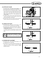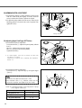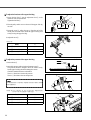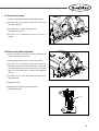
1
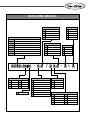
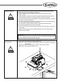
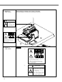
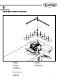
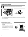
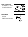
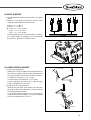
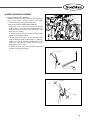
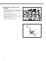
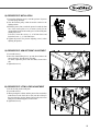
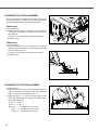
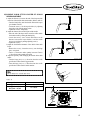
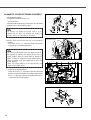
R
USER S MANUAL
SC9200 SERIES
SC9300 SERIES
High-Speed Overlock
Sewing Machine
lity
a
u
tQ
Besst Pricevice
Be st Ser
Be
1. Thank you for purchasing our product. Based on the rich expertise and
experience accumulated in industrial sewing machine production, SUNSTAR
will manufacture industrial sewing machines, which deliver more diverse
functions, high performance, powerful operation, enhanced durability, and
more sophisticated design to meet a number of user’s needs.
2. Please read this user’s manual thoroughly before using the machine. Make
sure to properly use the machine to enjoy its full performance.
3. The specifications of the machine are subject to change, aimed to enhance
product performance, without prior notice.
4. This product is designed, manufactured, and sold as an industrial sewing
machine. It should not be used for other than industrial purpose.
R
SunStar CO., LTD.
MACHINE MODEL
Fabric Weight
Series Code
SC92
Over-Edge Width
1
Extra Light ~ Light
3
3mm
2
Light ~ Medium
4
4mm
3
Medium ~ Heavy
5
5mm
4
Heavy ~ Extra Heavy
6
6mm
5
Very Heavy
7
7mm
Over-edge
SCC92 Over-edge + Condensed Stitch
SC93
Pitch of Feed Dog Teeth
Safety Stitch
SCT92 Over-edge + Variable Top Feed
SCT93 Safety Stitch + Variable Top Feed
SC94
Over-edge + Cylinder Bed
SCT94 Over-edge + Cylinder Bed + Variable Top Feed
SC95
Double Chain Stitch
1
1mm
Needle Space
2
1.25mm
0
1-Needle
3
1.6mm
2
2mm
4
2mm
3
3mm
5
2.5mm
5
5mm
SC92 04 N - 0 4 / 2 3 3 - 3 × 5
Stitch Type
Lift
Operation
41
#401
12
#512
0
Plain Seaming
2
Standard
03
#503
14
#514
1
Blind Stitch Hemming
3
High
04
#504
15
#515
2
Serging
4
Extra-high
05
#505
16
#516
3
Turn Up Down Hemming
5
Ultra-high
4
Shirring
5
Attaching Tape
8
Back Tacking
9
Versatile
1
1-Row Standard
2
2-Rows Standard 7
2-Rows Special
3
3-Rows Standard 8
3-Rows Special
4
4-Rows Standard 9
4-Rows Special
5
5-Rows Standard 0
5-Rows Special
N
Wrinkle-Free
Rows of Feed Dogs
6
1-Row Special
Table of Contents
1. SAFETY RULES ------------------------------------------------------------------------------------- 6
1) MACHINE DELIVERY-----------------------------------------------------------------------------------2) MACHINE INSTALLATION----------------------------------------------------------------------------3) MACHINE REPAIR ---------------------------------------------------------------------------------------4) MACHINE OPERATION---------------------------------------------------------------------------------5) SAFETY DEVICE------------------------------------------------------------------------------------------6) PLACEMENT OF CAUTION STICKERS------------------------------------------------------------7) CONTENTS OF CAUTION STICKERS ---------------------------------------------------------------
6
6
6
7
7
8
8
2. ENTIRE STRUCTURE ----------------------------------------------------------------------------- 9
3. SPECIFICATIONS ----------------------------------------------------------------------------------- 10
4. INSTALLATION--------------------------------------------------------------------------------------- 11
1) ADJUSTING BELT TENSION--------------------------------------------------------------------------- 11
2) BELT COVER INSTALLATION ------------------------------------------------------------------------ 11
3) TREADLE CONNECTION ------------------------------------------------------------------------------- 11
5. DIRECTION OF PULLEY ROTATION--------------------------------------------------------- 12
6. LUBRICATION---------------------------------------------------------------------------------------- 12
1) OIL ------------------------------------------------------------------------------------------------------------2) LUBLICATING OIL---------------------------------------------------------------------------------------3) OIL GAUGE / OIL WINDOW---------------------------------------------------------------------------4) MANUAL LUBRICATION------------------------------------------------------------------------------5) SILICONE OIL OF HR DEVICE------------------------------------------------------------------------6) LUBLICATING OIL CHANGE-------------------------------------------------------------------------7) OIL FILTER CHANGE ------------------------------------------------------------------------------------
12
13
13
13
14
14
14
7. STANDARD ADJUSTMENTS ------------------------------------------------------------------- 15
1) NEEDLE -----------------------------------------------------------------------------------------------------2) NEEDLE REPLACEMENT------------------------------------------------------------------------------3) THREAD TENSION ADJUSTMENT------------------------------------------------------------------4) PRESSER FOOT PLACEMENT / REMOVAL ------------------------------------------------------5) PRESSER FOOT PRESSURE ADJUSTMENT -----------------------------------------------------6) PRESSER FOOT STITCH WIDTH ADJUSTMENT -----------------------------------------------7) DIFFERENTIAL FEED RATIO ADJUSTMENT----------------------------------------------------8) MAX./MIN. DIFFERENTIAL FEED RATIO (feeding volume of the main feed dog)--------------------9) FEED DOG CHANGE ------------------------------------------------------------------------------------10) HEIGHT OF FEED DOG--------------------------------------------------------------------------------11) GRADIENT OF FEED DOG ADJUSTMENT ------------------------------------------------------12) HEIGHT OF SUB FEED DOG--------------------------------------------------------------------------
4
15
15
16
16
16
17
18
18
19
19
20
20
13) HEIGHT OF NEEDLE-----------------------------------------------------------------------------------14) LOEWR LOOPER ADJUSTMENT-------------------------------------------------------------------15) UPPER LOOPER ADJUSTMENT --------------------------------------------------------------------16) NEEDLE GUIDANCE ADJUSTMENT--------------------------------------------------------------17) DOUBLE CHAIN STITCH NEEDLE GUIDANCE ADJUSTMENT --------------------------18) PRESSER FOOT INSTALLATION-------------------------------------------------------------------19) PRESSER FOOT ARM LEFT/RIGHT ADJUSTMENT ------------------------------------------20) PRESSER FOOT LIFTING LEVER ADJUSTMENT ---------------------------------------------21) PRESSER FOOT LIFTING ADJUSTMENT --------------------------------------------------------22) PRESSER FOOT STOPPER ADJUSTMENT-------------------------------------------------------23) DOUBLE CHAIN STITCH LOOPER OF SC9300 SERIES ADJUSTMENT ----------------24) QUANTITY OF SUPPLIED THREAD ADJUSTMENT -----------------------------------------25) UPPER BLADE CHANGE -----------------------------------------------------------------------------26) LOWER BLADE CHANGE----------------------------------------------------------------------------27) OVEREDGE WIDTH ADJUSTMENT---------------------------------------------------------------28) HEMMING WIDTH ADJUSTMENT ----------------------------------------------------------------29) ADJUSTING UPPER FEED DOGS (SCT SERIES) -----------------------------------------------30) ADJUSTING OF UP/DOWN POSITION AND OPERATING RANGE ----------------------31) PRESSURE FOOT CHANGE--------------------------------------------------------------------------32) PRESSURE FOOT POSITION ADJUSTMENT----------------------------------------------------33) LEFT/RIGHT POSITION OF THE UPPER FEED DOG ADJUSTMENT --------------------34) ADJUSTING THE LIFT TIMING OF THE UPPER FEED DOG AND PRESSURE FOOT ----------35) ADJUSTING OF THE LIFTING QUANTITY BETWEEN THE PRESSURE FOOT AND THE UPPER FEED DOG-----
21
21
22
23
24
25
25
25
26
26
27
28
29
29
29
30
30
31
33
33
34
34
35
5
1
SAFETY RULES
The following set of safety rules categorized as Danger, Warning and Caution indicates possibilities of physical or property
damages if not fully observed.
DANGER : These safety instructions must be observed to be safe from danger when installing, delivering, or maintaining the
machine.
WARNING : These safety instructions must be observed to be safe from machine injuries.
CAUTION : These safety instructions must be observed to prevent machine errors.
1) Machine Delivery
Only qualified technicians who are familiar with the safety instructions should carry the
machine. Make sure to fully observe the following instructions when carrying the machine.
ⓐ The machine should be carried out by two or more people.
ⓑ Clean the oil to prevent accidents when delivering.
Danger
2) Machine Installation
Warning
3) Machine Repair
Caution
6
Installation environment may incur machine malfunction or breakdown. Make sure to meet
the following conditions.
ⓐ Undo a package from the top in order. Beware nails in wooden box.
ⓑ Dust and humidity can cause pollution and corrosion of the machine. Air conditioner
should be equipped and cleaned regularly.
ⓒ Do not expose the machine directly to the sun.
ⓓ Allow at least 50cm of space on each side of the machine for convenient maintenance.
ⓔ Explosion hazard
Do not operate machine in explosive atmospheres, where aerosol spray is used in large
quantity or oxygen is controlled.
ⓕ The lighting is not offered because of the nature of the machine, the lighting should be
install in the workspace by users.
[Reference] details of the machine installation are illustrated in 4. INSTALLAION.
Only SUNSTAR MACHINERY Co.,Ltd-trained and selected repair engineers should go repair
work.
ⓐ Turn off the power before cleaning or repairing the machine. Wait for 4 minutes so the machine
electricity is completely discharged.
ⓑ Do not change the specifications or any parts on the machine without confirmation from
SUNSTAR MACHINERY Co.,Ltd. Such change may cause safety accidents.
ⓒ Use only SUNSTAR MACHINERY Co.,Ltd parts when repairing machine.
ⓓ Put all safety cover on after repairing.
4) Machine Operation
Warning
SC 9200, SC 9300 Series is designed for applying sewing to knitwear and other similar
materials. Read thoroughly the following instructions.
ⓐ Read thoroughly and fully understand the manual before operating the machine.
ⓑ Dress for safety.
ⓒ Keep your hands or head away from the moving parts of the machine such as needle,
looper, spreader, take-up lever, and pulley when the machine is in operation.
ⓓ Do not remove the safety valve and all kinds of covers when the machine is in operation.
ⓔ Be sure to connect the ground wire
ⓕ Be sure the main power is turned off and the power switch is set to OFF before opening
the cover of any electrical component or control box.
ⓖ Turn the machine off when threading needles or inspecting the finished sewing.
ⓗ Do not press the pedals when you turn on the power.
ⓘ Do not drive when the cooling fan is blocked with dust. Clean the air filter in control box
once a week.
ⓙ Install the machine away from strong electromagnetic wave such as high frequency
welder as far as possible.
[WARNING]
When you operate machine, you should put the cover on to prevent physical injury by the
belt. Turn off the power before inspecting or adjusting.
5) Saeety Device
ⓐ Safety Label : Note directions for sewing machine use
ⓑ Belt Cover : Device to prevent physical injury by the motor or clothes from being stuck
in the machine
ⓒ Ginger Guard : Device to prevent finger to come in contact with the needle.
ⓓ Safety Valve : Device to protect worker’s eyes.
Caution
ⓐ
ⓑ
ⓓ
ⓒ
ⓐ
7
6) Placement of
Caution Stickers
Caution Stickers is attached on the machine for the safety.
Read thoroughly the manual before operating the machine.
CAUTION
Do not operate without finger guard
and safety devices. Before cleaning
and changing thread, needle and etc.
tum off main switch.
손가락 보호대와 안전장치 없이 작동하지
마십시오. 실과 바늘 교환시나 청소전에는
반드시 주전원의 스위치를 꺼주십시오.
Do not operate without a finger guard and a safety
protection device.
Turn off the combination switch before threading, lever
change, needle selection and cleaning.
손가락싸개 및 안전보호장치 없이 작업하지 마십시오.
실 꿰기, 레버 변경, 바늘 선택 및 청소 전에는, 통합스위
치를 off 상태로 바꾸십시오.
7) Contents of
Caution Stickers
Caution
(1)
Do not operate without a finger guard and a safety
protection device.
Turn off the combination switch before threading, lever
change, needle selection and cleaning.
손가락싸개 및 안전보호장치 없이 작업하지 마십시오.
실 꿰기, 레버 변경, 바늘 선택 및 청소 전에는, 통합스위
치를 off 상태로 바꾸십시오.
(2)
CAUTION
Do not operate without finger guard
and safety devices. Before cleaning
and changing thread, needle and etc.
tum off main switch.
손가락 보호대와 안전장치 없이 작동하지
마십시오. 실과 바늘 교환시나 청소전에는
반드시 주전원의 스위치를 꺼주십시오.
8
2
ENTIRE STRUCTURES
⑩
④
③
⑥
⑤
②
⑫
①
⑪
⑦
⑧
⑨
① FRAME
② Face plate
③ Top cover
④ Oil window
⑤ Hand pulley
⑥ Thread adjuster
⑦ Oil gauge
⑧ Presser foot
⑨ Power switch
⑩ Spool thread stand
Protective devices
⑪ Finger guard
⑫ Safety valve
9
3
SPECIFICATIONS
Model
SC(T) 9200 Series
Explanation
High-speed Over-edge Overlock sewing machine
Stitch form
ISO 504, 514
Use
Sewing speed
Stitch width
Needle
General sewing (knitwear)
max. 6000~8500 s.p.m (depend on the sewing material)
1.4~3.6mm
max. 3.8mm, 5mm (depend on the sewing material)
Organ DCx27 Nm 65
Needle distance
2 needle 4 stitching : 2mm
Presser foot lift
max. 5~5.5mm (depend on the sewing material)
Feeding volume adjustment system
Differential feed ratio
Differential feed ratio adjustment system
Lubrication system
Used oil
Button system
0.7~2 (depend on the sewing material)
Adjust screw and adjust lever
Automatic lubrication by oil pump
General sewing machine oil ISO VG 22
Model
SC(T) 9300 Series
Explanation
High-speed Thick Stuff Safety Stitch Overlock sewing machine
Stitch form
ISO 516, 401 + 514
Use
Sewing speed
Stitch width
Needle
Thick Stuff sewing (knitwear type)
max. 6000~7500 s.p.m (depend on the sewing material)
1.4~4.5mm
max. 5.5mm, 7mm (depend on the sewing material)
Organ DCx27 Nm 7~130
Needle distance
3, 5mm
Presser foot lift
max. 5~7mm (depend on the sewing material)
Feeding volume adjustment system
Button system
Differential feed ratio
0.7~2, 0.8~1.5
Differential feed ratio adjustment system
Lubrication system
Used oil
10
Adjust screw and adjust lever
Automatic lubrication by oil pump
General sewing machine oil ISO VG 22
4
INSTALLATIONS
1) ADJUSTING BELT TENSION
Caution
Check the OFF-status condition of a
power switch before adjusting tension on
the belt.
2cm
1) Put the sewing machine on the table, install the belt on the
sewing pulley, connect the belt to the motor pulley, and adjust
the belt tension.
2) adjust the length of deflection around 2cm when pressing the
center of the belt.
[Figure 1]
2) BELT COVER INSTALLATION
Install the belt cover① with the screw②
②
Install the belt cover for the safety
Caution
①
[Figure 2]
3) TREADLE CONNECTION
Connect the presser lever① to the treadle② by using the chain
③. Adjust the length of the chain③ to make the treadle② easier
to operate.
①
③
②
[Figure 3]
11
5
DIRECTION OF PULLEY ROTATION
The sewing pulley is turned clockwise when seeing from the end
of the pulley.
Caution
We recommend that you operate the
sewing machine at the rate of 4,000
s.p.m for 200hours (about a month) for
the durability.
The direction of the main shaft pulley①
and the motor pulley② rotation is
clockwise.
①
②
[Figure 4]
6
LUBRICATION
Check the OFF-status condition of a power switch before lubricating.
Warning
1) OIL
Mobil Velocite Oil No. 10(ISO Viscosity Grade 22)
Caution
12
Do not put foreign substances into the lubricating oil to prevent oil from aging of and breaking
down.
2) LUBICATING OIL
②
③
①
[Figure 5]
[Figure 6]
This sewing machine is shipped without oil. To use the machine without breakdown, open the rubber stopper① on the top cover and
lubricate oil to the top limit of the oil gauge③.
Caution
Small quantity of lubricating oil cause the machine breakdown and large quantity of lubricating oil
cause the quality deterioration because of the spattering of the oil.
3) OIL GAUGE/OIL WINDOW
Check the oil gauge③ before operating the sewing machine. Lubricate oil when the oil surface is under the 2 lines. Check the
spattering of the oil through the oil window② when operating the sewing machine.
4) MANUAL LUBRICATION
Lubricate about 2~3 drops of oil into the oil hole④, the needle
bar⑤, the upper looper holder⑥ when you use the sewing
machine first time or do not use it quite a while.
④
⑥
Caution
Lubricate oil part ④,⑤, and ⑥ to
prevent jamming during a trial run of the
machine at a high speed.
⑤
[Figure 7]
13
5) SILICONE OIL OF HR DEVICE
Put the silicone oil into the silicone oil tank①, ②.
Fill up the lack of oil before shrinking to prevent needle thread
and textile from damaging.
①
②
[Figure 8]
6) LUBRICATION OIL CHANGE
Change the oil after the first month and then change it every six
months. If not, the life of the sewing machine is going down.
1) Discharge the lubricating oil by loosening the oil outlet screw
①.
2) After discharging, fix the oil outlet screw① firmly.
①
[Figure 9]
7) OIL FILTER CHANGE
1) Remove the cover③ by loosening the screw②. Clean(oil) or change the oil filter① after checking it. (Replacement cycle: 6
months)
2) After insert the oil filter, install the cover③ and the screw②.
③
②
①
①
③
②
[Figure 10]
Make sure not to leak the remained oil from the oil filter when removing it.
Caution
14
7
STANDARD ADJUSTMENTS
1) NEEDLE
This sewing machine uses the DC×27 sized needle
Select the proper needle according to the thickness and type of
the sewing materials because of the various size of needle.
Japanese size
9
10
11
12
13
14
21
Metric size
65
70
75
80
85
90
130
2) NEEDLE REPLACEMENT
Warning
Check the OFF-status condition of a
power switch before setting the needle.
Loosen the screw① like figure12 and figure13 to change the
needle.
Check that the indentation(Scart) of the needle is turned to the
back of the sewing machine and insert the needle then tighten
the screw①.
①
[Figure 11]
× ○ ×
○ ×
[Figure 12]
[Figure 13]
Do not remove the needle set screw① completely when changing the needle.
Caution
15
3) THREAD TENSION ADJUSTMENT
To fasten the thread (to increase the thread tension), turn the
thread tension cap clockwise. To loosen the thread (to decrease
the thread tension), turn each thread tension cap
counterclockwise. Each thread tension should be set light as
possible but adjust the tension to form the beautiful stitches.
Strong
Reference
Adjust the thread tension according to
the sewing materials and the thread.
Weak
[Figure 14]
4) PRESSER FOOT PLACEMENT/REMOVAL
To remove the presser foot,
1) Turn the hand pulley to the highest point.
2) lower the presser lifting lever① and then rotate the presser
foot arm② toward the side.
①
To change the presser foot,
1) Turn the hand pulley to the highest point.
2) lower the presser lifting lever① and then reach the presser
foot arm② in good condition.
②
[Figure 15]
5) PRESSER FOOT PRESSURE ADJUSTMENT
The presser foot pressure should be set light but transfer the
sewing material precisely and adjust the pressure to form regular
stitches.
1) Loosen the adjusting nut① to adjust the presser foot pressure
and tighten the adjusting screw② as much as you need.
2) Fix the adjusting nut① by tightening after adjusting.
Weak
② Strong
①
[Figure 16]
16
6) PRESSER FOOT STITCH WIDTH ADJUSTMENT
⑤
Manual pulley
[Figure 17]
[Figure 18]
1) Turn the manual pulley pressing the button⑤ weakly then it will be pressed more deeply.
2) To increase the stitch width in the state of pressed button, turn the hand pulley to the (+) direction. Turn the manual pulley to the (-)
direction to decrease the stitch.
Note.
The relationship between the stamp of the hand pulley and the feed is noted in the table. The relationship
between the stamp of the hand pulley and the feed is changed according to the used textile and the differential
ratio. Adjust the stitch width according to the table 1.
Table1) Stitch width setting
SC9204-01/233-4
SC9204-02H/233-3
SC9214-03/333-2X3
SC(T)9214-03/333-2X4
SC9212-02/333-2X5
SC9316-03/233-3X5
SC(T)9316-03/333-5X5
SC9316H-A05/535-5X5
SC(T)9316-A04/435-5X5
SC9344-A04/435-5X3X4
1
0.6
0.6
0.6
0.6
0.6
0.6
0.6
0.8
0.8
0.8
2
1.13
1.13
1.13
1.13
1.13
1.13
1.13
1.5
1.5
1.5
3
1.66
1.66
1.66
1.66
1.66
1.66
1.66
2.2
2.2
2.2
4
2.19
2.19
2.19
2.19
2.19
2.19
2.19
2.9
2.9
2.9
5
2.72
2.72
2.72
2.72
2.72
2.72
2.72
3.6
3.6
3.6
6
3.25
3.25
3.25
3.25
3.25
3.25
3.25
4.3
4.3
4.3
7
3.8
3.8
3.8
3.8
3.8
3.8
3.8
5.0
5.0
5.0
17
7) DIFFERENTIAL FEED RATIO ADJUSTMENT
Check the OFF-status condition of a power switch before adjusting the differential feed.
Warning
②
③
①
[Figure 19]
[Figure 20]
1) To get the large differential feed ratio, loosen the nut① and turn the screw②, then lower the lever③. The end of the sewing
machine is shrinking. To get the small differentia feed ratio, turn the screw to (-) direction and raise the lever③.
2) After adjusting, tighten the nut①.
8) MAX./MIN. DIFFERENTIAL FEED RATIO
(FEEDING VOLUME OF THE MAIN FEED DOG)
1) Loosen the screw④, remove the cover⑤ from the back of the
sewing machine.
2) Loosen the nut⑥ and move up/down the link⑦. To increase
the differential feed ratio, move the link toward (+) direction.
To decrease the differential feed ratio, move the link⑦ toward
(-) direction.
3) After adjusting, place the cover⑤ on the back of the sewing
machine and tighten it with the screw④.
④
⑦
⑤
⑦
⑥
※ The adjustment of the differential feed ratio can be possible
but the stitch width is changed together.
[Figure 21]
18
9) FEED DOG CHANGE
①
1) Differential feed dog
Loosen the screw④, remove the differential feed dog③.
Install a new differential feed dog and tighten the screw④.
2) Main feed dog
Loosen the screw①, remove the main feed dog②. Install a
new differential feed dog and tighten the screw①.
②
④
③
[Figure 22]
10) HEIGHT OF FEED DOG
1) Turn the hand pulley until the main feed dog② reaches the
highest point.
2) According to the type of sewing machine, adjust the distance
(a) between the front face of the needle plate and the end of
the 2 or 3 feed dogs from the end of the main feed dog
backside. (Table 2)
To do this, loosen the screw①, move up/down main feed dog
as much as required.
3) Raise the feed dog by turning the hand pulley. When the end
of the main feed dog② is aligned with the front face of the
needle plate, the end of the differential feed dog③ should be
aligned with the front face of the needle plate. Tighten the
screw④.
a
②
③
[Figure 23]
Table 2)
Model
SC(T)9300, SC(T)9200 Series
SC(T)9316 - 04/435
SC9344 - 04/435
SC9316H - 05/535
a
0.7~0.9mm
b
0.5mm
1.0~1.12mm
0.3mm
1.1~1.3mm
0.3mm
19
11) GRADIENT OF FEED DOG ADJUSTMENT
1) When the main/differential feed dogs are raised from the
lowest position to the front face of the needle plate, the feed
dogs should be aligned with the front face of the needle plate.
2) To do this adjustment, open the side cover⑤ and loosen the
screw⑥. After adjusting the feed dog, turn the screw⑦.
⑥
⑤
⑦
[Figure 24]
12) HEIGHT OF SUB FEED DOG
Adjust the distance between the end of the main feed dos and the
end of the sub one in advance according to the type of the
sewing machine. (Table 2)
This distance is widening for the thick stuff and become narrow
for the thin stuff.
Loosen the screw⑧, fix the sub feed dog⑨ by adjusting it
up/down.
d
⑨
⑧
[Figure 25]
20
13) HEIGHT OF NEEDLE
SC 9300 Series
SC 9200 Series
1) Turn the hand pulley until the needle reaches to the highest
position.
2) Adjust the vertical height (a) between the front face of the
needle plate and the end of the needle as follows.
SC(T)92◇◇-◇◇/◆◇◇
SC(T)93◇◇-◇◇/◆◇◇
◆ - 2,3 type : (a) → 10.4~10.6mm
- 4 type : (a) → 11.8~12mm
- 5 type : (a) → 14.4~14.6mm
a
a
To do this adjustment, remove the rubber stopper② on the top
cover. Set the height by loosening the screw① and adjusting
the needle bar③ up/down. Fix it with the screw①.
[Figure 26]
①
②
③
[Figure 27]
14) LOWER LOOPER ADJUSTMENT
1) Lower looper setting distance
When the lower looper is farthest from the left (the bottom of
the needle bar), adjust the distance (b) between the end of the
lower looper and the center-line of the needle bar as follows.
0.03~0.05mm
SC(T)9200, SC(T)9300 series : b (3.7~3.9mm)
SC(T)9316-04/435, SC9344-04/435 : b (4.1~4.3mm)
To do this adjustment, loosen the screw⑤, adjust the looper
holder⑦ left/right then fix it by screw⑤.
2) Front/rear of lower looper adjustment
When the end of the lower looper reaches to the center-line,
the needle should be lain aslant about 0~0.03mm from the
lower looper toward the operator.
To do this adjustment, loosen the screw⑤ and adjust the
looper holder⑦ back/forth slightly by turning the adjusting
screw⑥ back/forth then fix it by screw⑤.
b
⑦
⑤
⑥
[Figure 28]
21
15) UPPER LOOPER ADJUSTMENT
1) When the upper looper is farthest from the left, adjust the
setting distance (b) between the end of the lower looper and
the center-line of the overlock needle depending on the
model. (Table 3)
(In case of 512 stitch, the distance (a) is between the center of
the looper eye and the center-line of the overlock needle.)
After this adjustment, tighten the screw② temporarily. When
the end of the upper looper is across the backside of the lower
looper, set the distance (c) about 0.5mm and the distance (d)
about 0.2mm. Then tighten the screw②.
2) When the upper looper is farthest from the left, adjust the
mentioned setting distance(b) between the end of the lower
looper and the center-line of the overlock needle then tighten
the screw②.
②
a
①
b
[Figure 29]
Table 3)
Model
SC(T)9300, SC(T)9204 Series
SC(T)9214 - 03/333
SC(T)9344 - 04/435
SC(T)9316H - 05/535
SC9212 - 02/333
SC9316 - A05/435
a
4.4~4.7mm
5.4~5.7mm
5.4~5.7mm
4.9~5.2mm
1~1.3mm
4.4~4.7mm
b
10.8mm
10.5mm
11.8m
12.8mm
10.5mm
12mm
ⓐ 0.2mm
ⓑ 0.5mm
[Figure 30]
22
16) NEEDLE GUIDANCE ADJUSTMENT
1) Overlock needle guidance adjustment
When the end of the lower looper reaches to the center-line of
the overlock needle, check the needle is lain aslant
0~0.03mm from the lower looper toward operator.
(Refer to 14) LOWER LOOPER ADJUSTMENT)
•Under the above condition to adjust the needle
guidance(after)①, adjust the needle guidance(after)① to
make the needle on a aslant by the guidance①. The
distance (a) is 0~0.05mm.
To do this, loosen the screw② and move the rear needle
guidance① back/forth as required.
•The end of the lower looper is on the center-line of the
needle to adjust the needle guidance(before) ①. When the
needle is on a slant by the needle guidance(after)①, the
distance(b) between the needle and the needle
guidance(after) is 0.1~0.2mm.
To do this, loosen the screw④ and move the front needle
guidance③ back/forth as required.
Front
Back
Front
①
Back
③
②
④
[Figure 31]
0.03~0.05mm
[Figure 32]
0~0.05mm
②
0.1~0.2mm
①
[Figure 33]
23
17) DOUBLE CHAIN STITCH NEEDLE GUIDANCE
ADJUSTMENT
1) When the double chain stitch needle is on the lowest point to
adjust the needle guidance(after)⑤, the distance(c) between
the double chain stitch needle and the needle guidance(after)
⑤ should be 0~0.05mm.
To do this, loosen the screw⑥ and move the needle
guidance(after)⑤ back/forth as required.
2) To adjust the needle guidance⑦, arrange the distance(d)
between the double chain stitch needle and the needle
guidance⑦ to 0.05~0.1mm.
To do this, loosen the screw⑧ and move the needle
guidance(before)⑦ back/forth as required.
⑧
⑦
Back Front
Front
Back
④
③
[Figure 34]
(c)
0~0.05mm
③
(d)
0.05~0.1mm
①
[Figure 35]
24
18) PRESSER FOOT INSTALLATION
1) Loosen the adjusting screw⑤ until the pressure of presser
foot arm spring decreased.
2) Turn the manual pulley when the needle reaches to the
highest position.
3) Install the presser foot to make the presser foot and the front
face of the needle plate to be in contact exactly for the
correspondence between the needle groove of the needle plate
and the presser foot.
To do this, loosen the screw①,② of SC9300 Series and
loosen the screws ③, ④ of SC9200 Series
4) Tighten the presser foot pressure adjusting screw⑤ when
adjusting the pressure.
②
③
④
①
[Figure 36]
19) PRESSER FOOT ARM LEFT/RIGHT ADJUSTMENT
1) Loosen the screw⑥.
2) Move the manual lifting lever⑦ up and down. Remove the
presser foot bar⑧ from the arm⑨ smoothly.
To do this, adjust the presser foot arm shaft⑩ from side to
side.
3) Tighten the screw⑥.
⑤
⑦
⑥
⑨
⑩
⑧
[Figure 37]
20) PRESSER FOOT LIFTING LEVER ADJUSTMENT
1) Fix the feed dog on the needle plate.
2) Loosen the screw⑪.
3) When pressing the collar⑫ and the presser foot arm shaft⑬
(make them not rock from side to side), turn the collar⑫ to
the arrow direction. Set the distance between the presser foot
lifting lever⑭ and the stopper⑮ to about 1mm.
4) Tighten the screw⑪.
⑮
⑫
⑪
⑬
⑭
1mm
[Figure 38]
25
21) PRESSER FOOT LIFTING ADJUSTMENT
Presser foot lifting is depending on the type of the sewing
machine. Identify the type of the sewing machine and select the
proper lifting quantity of the presser foot from the table 7.
SC9300 Series
1) Loosen the nut②.
2) When lowering the presser foot lifting lever①, the backside
of the presser foot should be at the edge of the front face of
the needle plate.
To do this, move the stopper bolt③ up/down as required.
3) Tighten the nut②.
①
③
②
SC9200 Series
1) Loosen the nut②
2) When lowering the presser foot lifting lever①, adjust the
distance(a) between the front face of the needle plate and the
back face of the presser foot.
To do this, move the stopper bolt⑪ up/down as required.
3) Tighten the nut②.
[Figure 39]
a
[Figure 40]
22) PRESSER FOOT STOPPER ADJUSTMENT
1) Loosen the nut⑥.
2) When lifting the presser foot, set the distance(b) between the
stopper④ and the presser foot arm⑤ at the 0mm. Adjust the
stopper④ up/down by loosening the screws ⑥, ⑦.
3) Tighten the nuts⑥, ⑦. Adjust the lifting quantity of the
presser foot on the bottom face of presser foot which is at the
center of the needle plate.
SC92◇◇-◇◇/◆◇◇
SC93◇◇-◇◇/◆◇◇
◆ - 2 type : ⓐ → height of presser foot 5mm
- 3 type : ⓐ → height of presser foot 5.5mm
- 4,5 type : ⓐ → height of presser foot 7mm
⑥
④
⑤
b
a
⑦
[Figure 41]
26
23) DOUBLE CHAIN STITCH LOOPER OF SC9300
SERIES ADUSTMENT
1) Adjust the distance (a) between the end of the looper and the
center-line of the double chain stitch needle. (Refer to table 4)
•Turn the hand pulley until the double chain stitch looper
goes farthest from left.
•Loosen the screw①, fix the looper holder③ by adjusting
from side to side with the setting values.
•Tighten the screw② temporarily.
2) Adjust the distance between the looper and the needle.
•Move the end of the looper to the center-line of the double
chain stitch needle by turning the hand pulley.
•Loosen the screw①, move it back and forth to set the
distance between the looper holder③ and the needle
groove at 0~0.05mm by turning adjusting screw②.
•Tighten the screw①.
3) Adjust the back/forth momentum of the double chain stitch
looper
•Remove the cover④, loosen the screw⑤, turn the hinge
pin⑥ as required.
•Turn to (-) direction to make quantity increased. Turn to
(+) direction to make quantity decreased.
4) Adjust the quantity when changing the double chain stitch
needle.
•Turn the hinge pin⑥ to (+) direction when the needle
specification is altered to the bigger number.
•Turn the hinge pin⑥ to (-) direction when the needle
specification is altered to the smaller number.
a
[Figure 42]
0~0.05mm
a
[Figure 43]
③
Note.
Do not loosen the screw⑤ too much.
①
②
Table 4)
Model
SC(T)9300 Series
SC(T)9316 - 04/435
SC(T)9344 - 04/435
a
1.4~1.6mm
[Figure 44]
1.6~1.8mm
④
⑥
⑤
[Figure 45]
27
24) QUANTITY OF SUPPLIES THREAD ADJUSTMENT
SC(T)9300 Series
③
1) Needle threads guidance
To adjust this, loosen the screws ①~⑥.
- SC(T)9300 Series
When the needle drops the loop of the looper, move the thread
guidance to the ⓐdirection like the figure.
①
④
Note.
To increase the quantity of threads, move it to (+)
direction like the figure. To decrease the quantity of
threads, move it to (-) direction like the figure.
2) Double chain stitch looper take-up lever and thread
guidance
Loosen the screw①~④, adjust the double chain stitch
looper take-up lever and thread guidance.
a
b
[Figure 46]
SC(T)9200 Series
⑥
Note.
The quantity of the double chain stitch looper thread can
be changed by adjusting the looper take-up lever or
thread guidance. When the needle drops the loop of the
looper, it causes the tangled thread and skipped stitches.
Adjust the double chain stitch looper take-up lever and
thread guidance.
Adjust the thread guidance to increase/decrease the
quantity of the looper thread.
⑤
[Figure 47]
⑤
3) Looper take-up threads guidance
Loosen the screw①~⑤, adjust the looper take-up threads
guidance to balance the quantity of top/bottom looper thread
(move to ⓐdirection to decrease the quantity and move to
ⓑ direction to increase the quantity).
①
a
④
b
③
②
[Figure 48]
①
②
④
③
[Figure 49]
28
25) UPPER BLADE CHANGE
1) Loosen the screw①. Move the fixed blade holder② to the
left to the utmost limit. Tighten the screw① temporarily.
2) Then remove the screw③ and movable blade④. To install
new movable blade, turn the hand pulley until movable blade
holder reaches to the lowest position within the movement
range. (Figure A) The cutting section of movable and fixed
blade is overlapped about 0.5~1.0mm depending on the
overedge width.
3) Overlap the cutting section of the movable/fixed blade to
cross the center point of the upper blade(A) and the center
point of the fixed blade⑥ like Figure B.
4) Put the thread between the movable and the fixed blade.
Check the cutting motion by turning the manual pulley.
⑧
⑦
③
④
②
⑤
①
⑥
[Figure 50]
FigureA
④
0.5mm~1.0mm
26) LOWER BLADE CHANGE
1) Loosen the screw①. Move the fixed blade holder② to the
left to the utmost limit. Tighten the screw① temporarily.
2) Loosen the screw⑤, remove the fixed blade⑥. Install new
fixed blade depending on the order 3), 4) above mentioned (1
UPPER BLADE CHANGE).
CAUTION The edge of the fixed blade is located 0~0.3mm
below the front face of the needle plate to install new fixed
blade.
⑥
[Figure 51]
FigureB
④
Caution
A
The edge of the fixed blade is located
0~0.3mm below the front face of the
needle plate to install new fixed blade.
⑥
27) OVEREDGE WIDTH ADUSTMENT
1) Loosen the screw①. Move the fixed blade holder② to the
left. Tighten the screw① temporarily.
2) Loosen the screw⑦, move the movable blade clamp⑧ from
side to side as required. Install the movable/fixed blade
depending on the order 3), 4) above mentioned (1 UPPER
BLADE CHANGE).
[Figure 52]
0~0.3mm
⑥
[Figure 53]
29
28) HEMMING WIDTH ADJUSTMENT
1) The hemming guidance③ bottom should be contact on the
front face of the needle plate slightly. To do this, loosen the
screw④ and move the bracket⑤ up/down as required.
2) To adjust the cutting width, loosen the screw④ and move the
hemming guidance③ from the side to side as required. Then
tighten the screw④.
④
right
②
left
③
①
cutting widht
[Figure 54]
29) Adjusting Upper Feed Dogs (SCT Series)
1) Forward/backward Feed Adjustment
Loosen the bar lifter①. Adjust the required quantity with the
lever②.
Move to (+) direction to increase the quantity.
Move to (-) direction to decrease the quantity.
Tighten the bar lifter①.
②
①
※ To adjust slightly, loosen the bar lifter① and then turn
bar lifter③ as required.
Tighten the bar lifter① after completing this adjustment.
[Figure 55]
③
[Figure 55]
2) Forward/backward Feed Adjustment
Loosen the screw①. Adjust the range by moving the stopper
② and ③.
②
Note.
The feed of the upper feed dog scale is 1mm.
The maximum value is 12. However, please do not
exceed the maximum value (table 6) for each model.
Table 6) Forward/backward Feed Adjustment Range
of the Upper Feed Dog
Model
30
③
②
①
Feed
SC(T)9214-03/333
SC(T)9316-03/233
1~6
1~6
SC(T)9316-A04/435K
1~6
[Figure 56]
30) Adjusting of Up/Down Position and Operating Range
1) Turn the pulley until the upper feed dog is in the highest
position.
Remove the upper cap①.
①
2) Loosen the bar lifter®È and set the upper feed adjustment
lever on the scale 2.
Then tighten the bar lifter③.
3) To adjust the up/down position,
3-1) loosen the screw④. Put the screw④ in the center of the
upper feed dog.
Then tighten the screw④.
3-2) turn the pulley until the upper feed dog is in the lowest
position.
3-3) loosen the screw⑤. Set the gap between the upper feed dog
and the differential feed dog to 0.2mm by moving the upper
feed dog.
3-4) Tighten the bar lifter③.
[Figure 57]
Reading(2)
③
4) To adjust up/down operating range of the upper feed dog
4-1) loosen the screw⑥. To set the operating range(a) of the
upper feed dog by the link⑦ as required, turn the pulley
until the upper feed dog is in the highest position and
measure the height of the upper feed dog.
4-2) Tighten the screw⑥.
[Figure 58]
Central line
Table 7)
Model
SC(T)9214-03/333
SC(T)9316-03/233
Height of the upper feed dog(a)
4.5
3.5
SC(T)9316-A04/435K
④
Upper feed dog
5.5
Differential feed dog
[Figure 59]
⑤
⑥
⑦
Top feed dog
Top feed dog track
⑧
[Figure 60]
[Figure 61]
31
① To adjust the front/rear of the upper feed dog
②
1) loosen the bar lifter①. Set the adjustment lever② to the
maximum value on the indicator.
Tighten the bar lifter①.
①
2) Turn the pulley until it moves to the end of the upper feed dog
rear side.
3) loosen the screw③. Adjust the gap (a) from the end of the
needle plate front side to the end of the upper feed dog front
side by moving the upper feed dog.
[Figure 62]
4) Adjust the screw③.
Table 8)
Model
③
a
SC(T)9214-03/333
SC(T)9316-03/233
23.5
18
SC(T)9316-A04/435K
18.5
[Figure 63]
② To adjust the pressure of the upper feed dog
1) loosen the nut①.
2) control the pressure with using the adjustment screw②.
The pressure should be enough to move the texture exactly
but the upper feed dog should not damage the texture.
Check the standard measures on the table 9.
Turn to (+) direction to increase the pressure.
Turn to (-) direction to decrease the pressure.
[Figure 64]
②
①
Note.
If the pressure is too low, irregular feed and noise could
be happened.
Table 9) The Height of the Pressure Adjustment
Screw for the Upper Feed Dog
Model
[Figure 65]
a
SC(T)9214-03/333
SC(T)9316-03/233
25.5
24
SC(T)9316-A04/435K
23.5
②
①
[Figure 66]
32
31) Pressure foot change
1) Turn the pulley until the needle is on the highest position.
①
2) Press the lever① and rotate the pressure foot arm② to the
side of the cloth plate.
3) Loosen the screw③. Change the pressure foot.
Then tighten the screw③.
③
4) Press the lever① and then the pressure foot arm② is
returned.
②
[Figure 67]
32) Pressure foot position adjustment
⑤
1) Loosen the nut④. Loosen the screw⑤ to eliminate the
pressure of the pressure foot arm②.
④
2) Turn the pulley until the needle is on the lowest position
3) Loosen the screw③. Match the part that the needle passes
through of the pressure foot and the needle hole on the needle
plate. Adjust the pressure foot to make the pressure foot and
upper side of the needle plate in parallel. Then tighten the
screw③.
4) Loosen the screw⑥. Move the pressure foot arm② for the
slight adjustment.
③
⑥
②
[Figure 68]
5) tighten the screw⑥.
6) Tighten the screw⑤ during pressure adjustment.
Then tighten the nut④.
needle
[Figure 69]
33
33) Left/right position of the upper feed dog adjustment
1) As mentioned in 32) Pressure foot position adjustment, adjust
the pressure foot position.
⑤
③
①
2) Loosen the screw① and ②. Adjust the upper feed dog③
position by moving upward feed guide⑤ and ⑥.
②
⑥
④
3) To make the upward feed bar④ move smoothly, check the
upward feed guide ⑤ and ⑥ position by turning the pulley.
4) Tighten the screw① and ②.
③
Note.
If the upward feed guide⑤ and ⑥ contacts to the
upward feed bar closely, problems can be caused.
[Figure 70]
34) Adjusting the lift timing of the upper feed dog and
pressure foot
⑨
⑩
1) Turn the pulley until the needle is on the lowest position.
2) Adjust the lift timing of the pressure foot
2-1) Press the pedal lifting lever
Maintain the gapⒶ by using the gauge. (Table 10)
2-2) Loosen the screw⑬. To contact the lever⑩, press collar⑨
to the arrow direction and match the pressure foot arm⑫ at
the same time.
Tighten the screw③.
⑬
⑧
⑦
⑫
Ⓐ
3) Adjust the lift timing of the upper feed dog
3-1) Press the pedal lifting lever⑦.
Maintain the gapⒶ by using the gauge. (Table 10)
3-2) Loosen the screw⑭. To contact the lever⑩, press collar⑪
to the arrow direction and match the pressure foot arm⑫ at
the same time.
Tighten the screw⑭.
[Figure 71]
⑭
⑪
⑩
Table 10) the lifting timing gap between the pressure
foot and the upper feed dog
SCT9200
SCT9300
Pressure foot
2mm
8mm
Upper feed dog
6mm
1mm
⑧
⑦
⑫
Ⓐ
[Figure 72]
34
35) Adjusting of the lifting quantity between the
pressure foot and the upper feed dog
SCT9300 Series
1) Turn the pulley until the bottom of the feed dog is below the
upper side of needle plate.
2) Confirm that the bottom side of the small pressure foot is
close to the upper side of needle plate. If not, follow the next
steps.
3) Loosen the nut②.
4) Pull down the pressure foot lifting lever③ until it is close to
the screw①.
To make the bottom side of the small pressure foot contact the
upper side of needle plate, adjust the height of the small
pressure foot by turning the screw① as required.
5) Return the pressure foot lifting lever③ and tighten the nut②
to fix the screw① safely.
6) Lift the pressure foot. Loosen the screw④.
7) Adjust the pressure foot lifting range(a) by the stopper⑤.
(Table 11)
8) Tighten the screw④.
SCT9200 Series
1) Turn the pulley until the bottom of the feed dog is below the
upper side of needle plate.
2) Loosen the nut②.
3) Pull down the pressure foot lifting lever③ until it is close to
the screw①.
Adjust the pressure foot lifting range(a) by turning the screw
① as required. (Table 11)
4) Return the pressure foot lifting lever③ and tighten the nut②.
5) Lift the pressure foot. Loosen the screw④.
Adjust the stopper⑤ to make it contact the pressure foot arm
⑥. Tighten the screw④.
③
①
②
[Figure 73]
⑥
④
⑤
[Figure 74]
Table 11) Lifting quantity between the pressure foot
and the upper feed dog
Model
Height of the upper feed dog
SC(T)9214-03/333
SC(T)9316-03/233
5.5
5
SC(T)9316-A04/435K
7
35