1
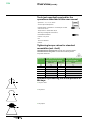
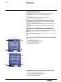
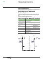
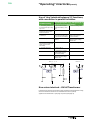
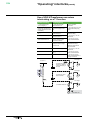
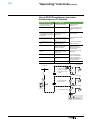
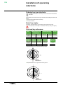
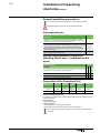
Medium Voltage Distribution
FBX
Mechanical key-type interlocking
Assembly - Operation
Instructions
www.schneider-electric.com
FBX
Content
■■ Introduction��������������������������������������������������������������������������������������������������������� 4
□□ Our Service Unit: our specialists, and suitably adapted services...��������������� 4
■■ Overview�������������������������������������������������������������������������������������������������������������� 5
□□ Eco-design concept and revalorization of the materials used����������������������� 5
□□ Responsibilities ��������������������������������������������������������������������������������������������� 5
□□ Particular instructions for operations and interventions on energized equipment�� 5
□□ Other technical notices to be consulted��������������������������������������������������������� 5
□□ Symbols & conventions���������������������������������������������������������������������������������� 5
□□ Tools (not supplied) required for the operations described in this user
manual��������������������������������������������������������������������������������������������������������������� 6
□□ Tightening torque values for standard assemblies (nut + bolt)���������������������� 6
□□ Symbols representing the actual position of the keys����������������������������������� 6
■■ General���������������������������������������������������������������������������������������������������������������� 7
□□ Interlocking by locks��������������������������������������������������������������������������������������� 7
□□ Operations and exploitation instructions�������������������������������������������������������� 7
□□ Changes or modification to installations�������������������������������������������������������� 7
□□ Locations of key-locks on the control panel��������������������������������������������������� 7
□□ Installation of key-type interlocks on site������������������������������������������������������� 7
■■ ”Operating” interlocks��������������������������������������������������������������������������������������� 8
□□ Role and applications������������������������������������������������������������������������������������� 8
□□ Interlocking the 'ring' between two Functional Units�������������������������������������� 8
□□ Use of 'ring' interlock between 2 C functions������������������������������������������������� 8
□□ Use of 'ring' interlock between 2 C functions, with connection in parallel forbidden���������������������������������������������������������������������������������������������������������������� 9
□□ Non-return interlock – HV/LV/Transformer����������������������������������������������������� 9
□□ Use of HV/LV/Transformer non-return interlocking on a T1 function����������� 10
□□ Use of HV/LV/Transformer non-return interlocking on a T2 function����������� 11
■■ Installation of operating interlocks����������������������������������������������������������������� 12
□□ Ordering key-type interlocks������������������������������������������������������������������������ 12
□□ Spare key supply����������������������������������������������������������������������������������������� 12
□□ Lock and key references������������������������������������������������������������������������������ 12
□□ General installation precautions������������������������������������������������������������������� 13
□□ Intervention levels���������������������������������������������������������������������������������������� 13
□□ Interlocking assemblies using locks (Earthing switch open – load break
switch open)����������������������������������������������������������������������������������������������������� 13
□□ Preparation of the Functional Unit��������������������������������������������������������������� 13
■■ Preparation of an earthing switch key-type interlock sub-assembly��������� 15
□□ Context��������������������������������������������������������������������������������������������������������� 15
□□ Precautions�������������������������������������������������������������������������������������������������� 15
□□ Fitting of two Ronis Nogapi locks����������������������������������������������������������������� 15
■■ Fitting an earthing switch key-type interlocking assembly������������������������� 19
□□ General�������������������������������������������������������������������������������������������������������� 19
□□ Supply (interlock kit)������������������������������������������������������������������������������������� 19
□□ Identification and locking out of the Functional Unit to be equipped with an
interlocking device������������������������������������������������������������������������������������������� 19
□□ Fitting of an earthing switch key-type interlock assembly to a C function��� 19
□□ Preparation of the front plate����������������������������������������������������������������������� 21
□□ Operating tests��������������������������������������������������������������������������������������������� 22
■■ Preparation of a load-break switch key-type interlock sub-assembly�������� 23
□□ Context��������������������������������������������������������������������������������������������������������� 23
□□ Precautions�������������������������������������������������������������������������������������������������� 23
□□ Fitting a Profalux Nogapi lock���������������������������������������������������������������������� 23
• Fitting a barrel on to the support���������������������������������������������������������������� 23
• Equipment for the support�������������������������������������������������������������������������� 24
□□ Assembly of two Ronis Nogapi locks����������������������������������������������������������� 26
2
AMTNoT153-02
FBX
Content (contd.)
• Equipment for the support�������������������������������������������������������������������������� 27
□□ Locks with micro-switches��������������������������������������������������������������������������� 27
■■ Fitting a load-break switch key-type interlocking assembly����������������������� 28
□□ General�������������������������������������������������������������������������������������������������������� 28
□□ Supply (interlock kit)������������������������������������������������������������������������������������� 28
□□ Identification and locking out of the Functional Unit to be equipped with an
interlocking device������������������������������������������������������������������������������������������� 28
□□ Location of the assembly����������������������������������������������������������������������������� 29
□□ Removal of the interlocking device�������������������������������������������������������������� 29
□□ Extraction of the mechanical control mechanism���������������������������������������� 29
□□ Installation of the interlocking device of the load-break switch�������������������� 31
• Fitting the interlocking device end stop������������������������������������������������������ 32
□□ Preparation of the front plate����������������������������������������������������������������������� 33
□□ Mechanical operation tests�������������������������������������������������������������������������� 33
■■ Notes������������������������������������������������������������������������������������������������������������������ 34
AMTNoT153-02
3
FBX
Introduction
Operations and maintenance may only be carried out by personnel who have
received suitable authorisation for the operations and manoeuvres they are
responsible for performing.
If this is not the case, please refer to our Service Unit or Training Centre.
All locking-out operations must be performed according to the "General Safety
Instructions booklet for Electrical Applications" UTE C 18 510 (or its equivalent
outside FRANCE).
Our Service Unit: our specialists, and
suitably adapted services...
■■ Guarantee extension contracts in relation to the selling of new equipment.
■■ Supervision of HVA switchgear installations.
■■ Technical advice, diagnoses of the facilities, expertise.
■■ Maintenance contracts adapted to operational constraints.
■■ Systematic or conditional preventive maintenance.
■■ Corrective maintenance in case of partial or complete failure.
■■ Supply of spare parts.
■■ Overhauling of equipment and requalification of installations in order to benefit
from new technologies and extend the life of your switchgear by limited investments.
Contact the Schneider Electric Service Unit for diagnoses and advice:
Working hours
33 (0)3 85 29 35 00
33 (0)3 85 29 36 30
or 33 (0)3 85 29 36 43
4
7 days per week/ 24 hours per day
Free phone No: 0 800 40 27 62
AMTNoT153-02
FBX
Overview
© - Schneider Electric - 2010. Schneider Electric , Schneider Electric logo and their
figurative forms are Schneider Electric registered trademarks.
The other brand names mentioned within this document, whether they be copyright
or not, belong to their respective holders.
Eco-design concept and revalorization of the
materials used
The design and life cycle of the equipment and switchgear manufactured by
Schneider Electric take environmental requirements into account (see page 10).
The design and manufacture of our packaging are both in conformity with the French
government decree N° 98-638 of 20 July 1998, concerning the account that is taken
of environmental requirements.
Responsibilities
Our devices are quality controlled and tested at the factory in accordance with the
standards and the regulations currently in force.
Apparatus efficiency and apparatus life depend on the compliance with the
installation, commissioning and operation instructions described in this user manual.
Non respect of these instructions is likely to invalidate any guarantee.
Local requirements especially about safety and which are in accordance with the
indications given in this document, must be observed.
Schneider Electric declines any responsibility for the consequences:
■■ due to the non respect of the recommendations in this manual which make
reference to the international regulations in force,
■■ due to the non respect of the instructions by the suppliers of cables and
connection accessories during installation and fitting operations,
■■ of any possible aggressive climatic conditions (humidity, pollution, etc.) acting in
the immediate environment of the materials that are neither suitably adapted nor
protected for these effects.
This user manual does not list the locking-out procedures that must be applied. The
interventions described are carried out on de-energized equipment (in the course of
being installed) or locked out (non operational).
Particular instructions for operations and
interventions on energized equipment
When commissioning and operating the equipment under normal conditions, the
General safety instructions for electrical applications must be respected, (protective
gloves, insulating stool, etc.), in addition to standard operating instructions.
All manipulations must be completed once started.
The durations (for completing the operations mentioned) given in the maintenance
tables are purely an indication and depend on on-site conditions.
Other technical notices to be consulted
■■ AMTNoT131
FBX (IS)
Installation - Commissioning
■■ AMTNoT132
FBX(IS)
Operations - Maintenance
■■ AMTNoT146
FBX (C13100)
Operations - Maintenance
Symbols & conventions
Code for a product recommended and marketed by Schneider-Electric
Tightening torque value Example: 1.6 daN.m
Mark corresponding to a key
CAUTION! Remain vigilant!
Precautions to be taken in order to avoid accidents or injury
FORBIDDEN! Do not do it!
Compliance with this indication is compulsory, non compliance with
this stipulation may damage the equipment.
IINFORMATION - ADVICE
Your attention is drawn to a specific point or operation
AMTNoT153-02
5
FBX
Overview (contd.)
Tools (not supplied) required for the
operations described in this user manual
Spanners: 7 ; 10 ; 13 ; 16 ; 26 mm
40 R.16 open-ended spanner
Ratchet handle + 2 extensions + universal joint + socket
sizes 10 and 13 mm
Torque wrench + socket sizes 16, 26
Allen key for hexagonal screw size 3, 4
Flat headed screwdriver
Hammer + Pin punch
File
Torx 2.5 screwdriver
Reamer
Tightening torque values for standard
assemblies (nut + bolt)
Threaded fasteners without grease: assembly with ungreased washers.
Threaded fasteners with grease: mounted with the washer greased.
Use grease referenced:
Diameter Zinc plated steel fasteners Stainless steel fasteners
without grease (daN.m)
with grease (daN.m)
Class 6.8
Class 8.8
A2-70
M6
0.7
0.9
0.7
M8
1.6
2.1
1.6
M 10
3.2
4.3
3.2
M 12
5
6.6
5
M 14
8.7
11.6
8.7
M 16
13.4
17.9
13.4
M 20
26.2
35
26.2
Symbols representing the actual position of
the keys
■■ Key free - fitted.
■■ Key absent.
■■ Key captive.
6
AMTNoT153-02
FBX
General
Interlocking by locks
Interlocking using key-locks is a necessary requirement to: Guarantee certain
operational functions,
■■ have the switchgear controlled by a line isolator or earthing switch,
■■ block access.
This manual deals with the two types of key-lock-type locking:
■■ locking a function, Operational interlocking
Operations and exploitation instructions
The information given in this manual is required for the elaboration of operating
instructions and use of the equipment.
These procedures are specific to each individual installation and are produced by the
customer.
The instructions for operational use must be displayed on the Functional units
concerned.
Changes or modification to installations
Any changes or modifications to the installations must trigger an update of the
padlock interlock orders and the associated documents.
A general interlock plan must be systematically drawn up and updated as and
when the installation is changed.
Locations of key-locks on the control panel
Function C
Key
2
1
2
3
4
5
1
4
Lock load-break switch "open"
Additional lock Load-break switch "Open"
Key-lock - Earthing switch “Open”
Key-lock - Earthing switch “Closed”
Lock load-break switch "Open"
3
Functions T1 and T1c
5
4
3
Installation of key-type interlocks on site
The installation of key-type interlocks requires:
■■ Purchase of the components and elements required,
■■ The use of suitable tools, (See page 6),
■■ Fitting instructions (see page15 & 19).
AMTNoT153-02
7
FBX
”Operating” interlocks
Role and applications
Operational interlocks are used to control the sequences of operational manoeuvres
and lockout operations under normal service and safety conditions.
Interlocking the 'ring' between two
Functional Units
Conditions the closing of the earthing switch on a Functional Unit in relation to the
opening either of a load-break switch or the line isolator on the second Functional
Unit.
Only applies to C functions (see page 8).
There is no 'ring' interlock between the 2 T2 functions.
Use of 'ring' interlock between 2 C functions
Commissioning
De-energizing
■■ The earthing switches are
locked ”open” using keys 1 &
2.
■■ Open load-break switch
C2 and lock with key 2.
■■ Close the earthing switch.
■■ Keys 1 and 2 should be
present in the locks of ”open”
load-break switches.
■■ Recover Key 2.
■■ Return to C2.
■■ Unlock then close the
switches.
■■ Go to C1.
■■ Introduce Key 1 into the
earthing switch lock and
unlock immediately.
■■ Open load-break switch
and lock with key 1.
■■ Verify that there is no
voltage across the voltage
indicator units.
■■ Recover Key 1.
■■ Close the earthing switch.
■■ Introduce Key 2 into the
earthing switch lock and
unlock it immediately.
■■ Check that there is no
voltage across the voltage
indicator units.
FBX 1: C -...
FBX 2: C -...
1
2
C1
2
8
&
1
AMTNoT153-02
FBX
”Operating” interlocks (contd.)
Use of 'ring' interlock between 2 C functions,
with connection in parallel forbidden
Commissioning
De-energising the 'ring', with passage of
the second "incoming feeder"
■■ The earthing switches C2
& C3 are locked ”open” using
keys 1 & 2.
■■ Open load-break switch
C2 and lock with key 1, then
key 3.
■■ Close the earthing switch.
■■ Keys 1 and 2 should be
present in the locks of ‘open’
load-break switches.
■■ Recover keys 1 & 3.
■■ Return to C2.
■■ Lock the load-break switch
C1 with key 3.
■■ Introduce key 3 into the
lock of the load-break switch
C1 and unlock it immediately.
■■ Introduce Key 2 into the
earthing switch lock and
unlock immediately.
■■ Recover Key 3.
■■ Close the load-break
switch C1.
■■ Verify that there is no
voltage across the voltage
indicator units.
■■ Introduce this key into the
second lock of the load-break
switch C2 and unlock it
immediately.
■■ Go to C3.
■■ Close the earthing switch.
■■ Close the load-break
switches C2 & C3.
■■ Recover Key 2.
■■ Introduce Key 1 into the
earthing switch lock and
unlock it immediately.
■■ Check that there is no
voltage across the voltage
indicator units.
FBX 1: C - C - T1
3
FBX 2: C -...
3 1
2
C1
C2
2
C3
1
Non-return interlock – HV/LV/Transformer
Prohibits access to the Functional Unit's cable compartment and transformer as long
as the Functional Unit and the LV circuit breaker are in service (closed).
Applies to Functional Unit's T1 (see page 10) and T2 (see page 10).
AMTNoT153-02
9
FBX
”Operating” interlocks (contd.)
Use of HV/LV/Transformer non-return
interlocking on a T1 function
Commissioning
De-energizing
■■ Lock earthing switch
"open" using Key 1.
■■ Open the load-break
switch of function T1.
1st case, insulated
transformer:
■■ Go to the low voltage
switchboard, introduce Key 1
into the CB lock and unlock it
immediately.
■■ Go to the LV switchboard,
open and unplug the main
CB.
□□ unlock transformer access
(or plugin terminals) using
Key 2.
■■ Plug in then close the LV
CB.
■■ Lock this CB in its ‘withdrawn’
position using Key 1.
2nd case, transformer with a
double lock fitting:
■■ Come back to function T1.
■■ Recover key 1 and go
back to function T1.
□□ introduce key 1 into the
transfer lock,
■■ Close the load-break
switch of the function T1.
■■ Introduce Key 1 into the
earthing switch lock and
unlock it immediately.
□□ recover key 3 to gain
access to the transformer
■■ Check that there is no
voltage across the voltage
indicator units.
3rd case, transformer (with
metalclad enclosure), >
2000kVA or with external
plug-in terminals:
■■ Close the earthing switch.
□□ introduce key 2 into the
transfer lock,
■■ Lock earthing switch using
Key 2.
□□ recover key 3 to gain
access to the transformer
■■ Go to the transformer.
□□ recover key 4 to gain
access to the transformer or
the plug-in terminals.
Low Voltage
2 3 4
Function T1
3
RU
1
3) Transformer (with
enclosure) > 2000kVA
or with external plug-in
terminals
4
1
Low Voltage
3
2
1
2) Transformer with a
double lock fitted
23
RU
Low Voltage
2
1
1) Insulated transformer
or
GE
10
1
Generator Unit
AMTNoT153-02
FBX
”Operating” interlocks (contd.)
Use of HV/LV/Transformer non-return
interlocking on a T2 function
Commissioning
De-energizing
■■ Earthing Switch is already
locked ‘open’ with key 1.
■■ Trip the circuit breaker.
1st case, insulated
transformer:
■■ Recover Key 1.
■■ Open the line isolator.
□□ unlock transformer access
(or plugin terminals) using
Key 2.
■■ Go to the low voltage
circuit breaker, introduce Key
1 into the CB lock and unlock
it immediately.
■■ Go to the LV switchboard,
open and unplug the master
circuit breaker.
2nd case, transformer with a
double lock fitting:
■■ Plug in then close the LV
circuit breaker.
■■ Lock this circuit breaker in
its ‘withdrawn’ position using
Key 1.
□□ unlock transformer access
with key 2,
■■ Return to the Functional
Unit.
■■ Recover key 1 and go
back to function T2.
□□ recover key 3 to unlock
the plug-in terminals.
■■ Close the line isolator.
■■ Introduce Key 1 into the
earthing switch lock and
unlock it immediately.
3rd case, transformer (with
metalclad enclosure), >
2000kVA or with external
plug-in terminals:
■■ Re-arm and trip the circuit
breaker.
■■ Check that there is no
voltage across the voltage
indicator units.
□□ introduce key 2 into the
transfer lock,
■■ Close the earthing switch.
□□ recover key 3 to gain
access to the transformer,
■■ Lock earthing switch using
Key 2.
□□ recover key 4 to gain
access to the transformer or
the plug-in terminals.
■■ Go to the transformer.
Low Voltage
2 3 4
Function T2
3
RU
1
3) Transformer (with
enclosure) > 2000kVA
or with external plug-in
terminals
4
Low Voltage
3
1
2) Transformer with a
double lock fitted
1
23
RU
2
Low Voltage
2
1
1) Insulated transformer
RU
1
GE
AMTNoT153-02
Generator Unit
11
FBX
Installation of operating
interlocks
Ordering key-type interlocks
For all interlock orders, it is necessary to enclose the material characteristics
data sheet.
Clearly identify the mechanical control type mechanism before ordering the interlock kit.
Stating:
■■ The type of lock chosen (Ronis or Profalux),
■■ The type of interlock.
Spare key supply
On request, Schneider Electric may sometimes supply spare keys to locks.
The spare keys must be kept in a dedicated, closed, key safe (not supplied).
Lock and key references
Use
FBX function + Low
Voltage (LV)
Description 1/4 turn left 1/4 turn right
Transformer (TR)
door lock
TR + LV
special lock Deadlocks
Profalux PBA90GPS3003 PBA90DPS3003 PSP1CPS3000 PSP2FPS3000 PVE11CPS3000
Ronis
Use
RBA90GEL3003 RBA90DEL3003 RSP1CEL3000 RSP2FEL3000 RVE11CEL3000
LV
GE
Description 1/4 turn right
Profalux
Ronis
key switch
transfer lock
Wrench
PBA90DPS3333 PVC11CPS3000 PST3PS3000
PCHF5
RBA90DEL3333 RVC11CEL3000
RCEL5
RST3EL3000
■■ Representative of a ¼ turn left to leave the key captive.
Ronis
Direction A
■■ Representative of a ¼ turn right to leave the key captive.
Ronis
Direction B
12
AMTNoT153-02
FBX
Installation of operating
interlocks (contd.)
General installation precautions
Prior to fitting the locks, mark the direction and location on the plate.
Respect the tightening Torques. DO NOT OVER TIGHTEN.
Intervention levels
Definition
Levels
Operations recommended in the instructions manual "installation - operation maintenance", carried out bysuitably qualified personnel having received training
allowing them to intervene whilst respecting the safety rules.
1
Complex operations, requiring specific expertise and the implementation of
support equipment in accordance with Schneider Electric procedures. These are
carried out by Schneider Electric or by a specialised technician, trained by
Schneider Electric in the implementation of procedures, and who is equipped
with specific equipment.
2
All preventive and corrective maintenance, all renovation and reconstruction
work is carried out by Schneider Electric.
3
Interlocking assemblies using locks
(Earthing switch open – load break switch
open)
Fitting of locks
Levels
Functions
1
2
3
Preparation of the locking casing of the earthing switch
-
■
■
Fitting locking operations by keylocks to the earthing switch
-
■
■
Preparation of the locking casing of the load-break switch
-
■
■
Fitting a lock-type interlock on the load-break switch
-
■
■
Preparation of the Functional Unit
Intervention Duration Busbar Cables
Load-break Earthing
switch
switch
Normal
1h
Deenergized
Deenergized
Open
Open
Possible
1h
Energized
Energized
Open
Open
Locking out the Functional Unit
All locking-out operations must be performed according to the particular rules for the
network concerned.
Tools required:
Please refer to page 6.
If wiring is present:
■■ de-energize the LV auxiliary power supplies.
■■ disconnect all of the wires connected to the control mechanism.
For all interlocking installation operations, it is necessary to remove the FBX
front plate.
AMTNoT153-02
13
FBX
Installation of operating
interlocks (contd.)
■■ Unscrew the 2 fixing screws of the panel (size 4 Allen key).
■■ Remove the panel.
14
AMTNoT153-02
FBX
Preparation of an earthing
switch key-type interlock
sub-assembly
Context
In the supply of a key-type interlock kit, this assembly is already done. Therefore, go
to page 19 directly.
Nevertheless, in certain cases, (modifications, replacement, etc.), these assemblies
may have to be removed and then re-fitted on the site.
Precautions
For fitting the locks, it is necessary to
mark their direction and their location
on the plate in accordance with page 7.
Interlocks
1/4 turn
left
1/4 turn
right
Earthing switch
Open
Closed
Fitting of two Ronis Nogapi locks
■■ Insert a ring on to each barrel of the lock.
■■ Position the barrels on the support.
■■ Fix the barrels on to the support (26 mm spanner).
■■ Tighten to the indicated torque.
1
■■ Fit the probe with a CHC M4x12 bolt + ES4 washer + Nylstop nut.
■■ Do not tighten this bolt .
AMTNoT153-02
15
FBX
Preparation of an earthing
switch key-type interlock
sub-assembly (contd.)
■■ Apply grease to the 2 faces of the slide of the probe.
■■ Place an M6 flat washer on to this stud, with a small deposit of grease.
■■ Position the probe as shown.
■■ Fix the probe using a CHC M4x6 bolt + ES4 washer + M4 washer
(Allen key size 3).
■■ Hook on the spring to the mobile blanking piece.
16
AMTNoT153-02
FBX
Preparation of an earthing
switch key-type interlock
sub-assembly (contd.)
■■ Hook on the spring to the support.
■■ Position the mobile blanking
piece as shown. Remain vigilant because in this position, the spring is taut.
■■ Insert the keys and turn them to place them in a flat position.
■■ Position the 2 shims: the narrowest part at the bottom.
■■ Position the 2 shims as shown.
■■ Position the cams as shown
■■ Screw on the nut positioned at the extremity to maintain all of the equipment on
each barrel.
AMTNoT153-02
17
FBX
Preparation of an earthing
switch key-type interlock
sub-assembly (contd.)
■■ Tighten to the indicated torque. (16mm spanner).
0.25
0.25
■■ Apply grease to the 2 faces of all of the slots of the blanking piece.
■■ Position the blanking piece in its location.
■■ Fix the blanking piece using 2 CHC M4x6 bolts + ES4 washers + M4 flat washers
(Allen key size 3).
■■ Tighten the 2 screws.
■■ Position the probe in order to operate either of the keys.
■■ Make sure that the keys turn easily and that there is no friction.
18
AMTNoT153-02
FBX
Fitting an earthing switch
key-type interlocking assembly
General
Intervention Duration Busbar Cables
Load-break Earthing
switch
switch
Normal
1 h 30
Deenergized
Deenergized
Open
Closed
Possible
1 h 30
Energized
Energized
Open
Closed
Locking out the Functional Unit
All locking-out operations must be performed according to the particular rules for the
network concerned.
Tools required:
please refer to page 6.
Parts required:
interlock kit (see Supply (interlock kit)).
Supply (interlock kit)
Key
1 Locking devices
2 Captive nut (positioned on the support waiting to be assembled on to the FBX
cross-member)
3 Assembly bolt not tightened
4 Fixing bolt
Identification and locking out of the
Functional Unit to be equipped with an
interlocking device
On the table, identify the position of the Functional Unit to be equipped (1, 2, 3 or 4).
See lock out instructions in page 13.
If necessary lock out the load-break switches and earthing switches.
Fitting of an earthing switch key-type
interlock assembly to a C function
■■ The interlocking device is equipped with (see page 15).
■■ Remove the front panel (Allen key size 4).
■■ Mark the position of the interlocking device.
AMTNoT153-02
19
FBX
Fitting an earthing switch
key-type interlocking assembly
(contd.)
■■ Recover the 2 captive nuts and slide them on to the 2 holes of the front cross
member.
■■ Insert the entire device through the inside of the compartment.
If necessary remove the locking devices of the panel in accordance with
page 29
■■ Position vertically the device on to its 2 fixing points.
■■ Check that the mobile blanking piece is in its housing.
■■ Align and fix the device using the 2 screws, without tightening them.
20
AMTNoT153-02
FBX
Fitting an earthing switch
key-type interlocking assembly
(contd.)
10 mm
■■ Functions C & T1: position a shim under the probe in order to obtain the 10 mm
dimension.
■■ Function T2: no shim.
■■ Assemble the probe and the earthing switch position indicator with the bolt
supplied (Allen key size 3 + 7 mm open-ended spanner).
■■ Check that the key turns easily, without blocking in the barrel of the lock.
■■ Displace the assembly laterally and in depth to obtain the correct operation.
■■ Tighten the 2 fixing screws.
Preparation of the front plate
■■ Mark the cut-out to be removed from the plate.
AMTNoT153-02
21
FBX
Fitting an earthing switch
key-type interlocking assembly
(contd.)
■■ Using a hammer and a large pin punch, remove the cut-out.
■■ If necessary, slightly file down the parts which are not completely flat and smooth.
■■ Re-fit the front plate on to the Functional Unit C (Allen key size 4).
Operating tests
Proceed with operating mechanical tests of the interlocking device.
22
AMTNoT153-02
FBX
Preparation of a load-break
switch key-type interlock
sub-assembly
Context
With the supply of a key-type interlock kit, this assembly is already done. Therefore,
go to chapter 9 directly.
Nevertheless, in certain cases, (modifications, replacement, etc.), these assemblies
may have to be removed and then re-fitted on the site.
Precautions
For fitting the locks, it is necessary to mark
their direction and their location on the plate
in accordance with page 7.
Locking
1/4 turn left
Load-break switch
Open
Fitting a Profalux Nogapi lock
Fitting a barrel on to the support
■■ Insert a ring on to the barrel of the lock.
■■ Position the barrel on to the support, as shown.
■■ Tighten the nut (26 mm spanner).
1
■■ Position the cam.
AMTNoT153-02
23
FBX
Preparation of a load-break
switch key-type interlock
sub-assembly (contd.)
■■ Introduce the key and turn it to place it in a flat position.
■■ Screw in and tighten the nut to the indicated torque whilst maintaining the barrel of
the lock (key 40 R.16).
0.25
Equipment for the support
■■ Grease the part above and underneath the vertical lug of the support.
■■ Grease the passage slot of the blanking off piece.
26
■■ Grease the 2 sides of the blanking off piece.
26
24
AMTNoT153-02
FBX
Preparation of a load-break
switch key-type interlock
sub-assembly (contd.)
■■ Insert the blanking off piece intothe slot of the support.
■■ At the same time, the lug of the suppport must go in to the notch of the blanking off
piece.
■■ Maintain the blanking off piece raised whilst moving it on to its drive pin.
■■ Fit a flat washer.
■■ Fit the circlips.
AMTNoT153-02
25
FBX
Preparation of a load-break
switch key-type interlock
sub-assembly (contd.)
■■ Hook on the spring in to the indicated hole, at the rear of the support.
■■ Hook the other extremity of the spring on to the drive pin.
■■ Check that the device is functioning properly whilst operating the key several
times.
Assembly of two Ronis Nogapi locks
■■ Directly fix the barrels on to the locks of the support (1).
■■ Tighten the nuts (26 mm spanner).
1
1
■■ Place the spring (2).
26
AMTNoT153-02
FBX
Preparation of a load-break
switch key-type interlock
sub-assembly (contd.)
■■ Position the 2 cams (3) as shown above.
■■ Tighten the nuts (key 40 R.16).
■■ Position the spring (4).
0.25
Equipment for the support
Proceed in exactly the same way as for chapter "Equipment for the support" in page
23.
Locks with micro-switches
■■ The micro-switch is fixed on to the rear side of the device.
■■ The micro-switch is held in place by 2 screws moderately tightened.
■■ The wiring loom is connected up by two elbowbend lugs.
AMTNoT153-02
27
FBX
Fitting a load-break switch
key-type interlocking assembly
General
Intervention Duration Busbar Cables
Load-break Earthing
switch
switch
Normal
1 h 30
Deenergized
Deenergized
Open
Closed
Possible
1 h 30
Energized
Deenergized
Open
Closed
Locking out the Functional Unit
All locking-out operations must be performed according to the particular rules for the
network concerned.
Tools required:
please refer to page 6.
Parts required:
■■ interlock kit (see page 28),
■■ shim.
Supply (interlock kit)
Key
1 Fitted support
2 Bolts
3 Self-locking washer
4 Additional self-locking washer for T1
5 End stop
6 Self-tapping screws
7 Self-locking washer
8 Flat washer
Identification and locking out of the
Functional Unit to be equipped with an
interlocking device
On the switchboard, identify the position of the function to be equipped (1, 2, 3 or 4).
See lock out instructions in page 13.
If necessary, lock out the load-break switches and earthing switches.
28
AMTNoT153-02
FBX
Fitting a load-break switch
key-type interlocking assembly
(contd.)
Location of the assembly
■■ The mechanical control mechanism is accessible.
■■ The locking operation by keylocks will be fitted in the upper part.
Removal of the interlocking device
■■ Using a marker, mark out the position of the vertical locking device on its support.
■■ Unscrew and remove the 2 fixing bolts (2 open-ended spanners size 10).
■■ Extract the vertical locking device.
Extraction of the mechanical control
mechanism
■■ Insert the earthing switch lever.
■■ Operate the earthing switch very slowly so that its blades are lifted.
AMTNoT153-02
29
FBX
Fitting a load-break switch
key-type interlocking assembly
(contd.)
■■ Position the shim on the lower rear side of the spring.
■■ Leave the earthing switch to rest again on this shim.
■■ The shim is in place.
■■ Remove the operating lever for the earthing switch.
■■ Unscrew the 4 self-locking fixing nuts (3 to the left, 1 to the right) of the control
mechanism.
1.6
1.6
1.6
1.6
■■ Use gloves to take hold of the control mechanism.
■■ Extract the control mechanism whilst pulling the 2 drive rods in the lower part.
30
AMTNoT153-02
FBX
Fitting a load-break switch
key-type interlocking assembly
(contd.)
Installation of the interlocking device of the
load-break switch (for the marks, see page 28)
■■ Place the mechanical control mechanism in a flat position.
■■ Screw in the 2 screws by two threads (2) with 1 washer each (3).
Place 2 washers under each screw for a functional interlocking T1.
■■ Grease the passage of the support.
26
■■ First of all, insert the support (1) on to the 2 bolts, between the washers and the
plate of the mechanical control mechanism.
■■ Then secondly, hook the small lug on at the front of the support, behind the back of
the plate.
AMTNoT153-02
31
FBX
Fitting a load-break switch
key-type interlocking assembly
(contd.)
■■ Then centre the support in the passage slot, which has been previously greased.
■■ Align the support in relation to the edge of the mechanical control mechanism.
■■ Check the free functioning of the interlocking device. The key must go back to the
original position.
■■ Tighten the 2 fixing screws of the support, whilst checking the free functioning of
the interlocking device.
■■ Re-fit the mechanical control mechanism on to the FBX, whilst poceeding in
reverse order as for dismantling (see page 29).
Replace the 4 self-locking nuts by new ones. Tighten to the indicated
torque.
Fitting the interlocking device end stop (for the marks, see
page 28)
■■ Very lightly bore the 2 holes of the fixing screws.
■■ Place the end stop (5). Screw in the 2 screws (6) (+ washers 7 and 8) without
tightening (Torx 2,5 screwdriver).
It is necessary to close the load-break switch to adjust the end stop.
Caution, the busbar may be energised !
32
AMTNoT153-02
FBX
Fitting a load-break switch
key-type interlocking assembly
(contd.)
■■ Slightly incline the end stop to avoid it leaving the cam when in operation.
■■ Keep a space of 1.5 to 2mm between the end stop and the cam. This space avoids
any risk of shock during the operations.
6SDFH
■■ Moderately tighten the 2 screws.
Preparation of the front plate
■■ Remove the corresponding cap of the lock.
■■ If necessary, slightly file down the parts which are not completely flat and smooth.
■■ Replace the plate.
Mechanical operation tests
Proceed with mechanical operating mechanical tests of the interlocking device.
AMTNoT153-02
33
Appendices
34
Notes
AMTNoT153-02
Appendices
AMTNoT153-02
Notes
35
© 2011 Schneider Electric - All Rights Reserved
Schneider Electric
35, rue Joseph Monier
CS 30323
92506 Rueil-Malmaison Cedex, France
RCS Nanterre 954 503 439
Capital social 896 313 776 €
www.schneider-electric.com
AMTNoT153-02
As standards, specifications and designs change over time, request confirmation of information
provided in this publication.
This document was printed
on environmentally friendly paper
Publication: Schneider Electric
Design: Schneider Electric
Printing:
12-2010