Download User Manual - RWW Engineering
Transcript
0
0
0
0
0
0
Metalclad cubicle
NEX Merlin Gerin
17.5 kV
User
Manual
2003
N
NE
NEX
Contents
General description
3
Feeder/incomer cubicle
3
Incoming/outgoing feeder without VT or with fixed VT
Front panel
Left-hand view
3
3
3
Feeder/incomer cubicle
4
Incoming/outgoing feeder with withdrawable VT
Front panel
Left-hand view
4
4
4
Busbar voltage transformer cubicle
5
Front panel
Left-hand view
5
5
Coupler/riser cubicles with withdrawable VT
6
Front panel
Left-hand view
Left-hand view
6
7
7
Cubicle identification
Front panel removable part
Earthing switch voltage presence
Withdrawable voltage transformer
Symbols
8
8
8
9
9
Basic cubicle
Removable part
9
9
Removable part extraction table
List of accessories supplied with the switchboard
Glossary of abbreviations
10
10
10
Access to interior of the cubicle
11
Access possibilities to the cubicle
Extracting the removable part
Installing the removable part
Access to the MV cable connection compartment
11
12
14
15
Cubicle without voltage transformer
Cubicle with fixed voltage transformer
Cubicle with withdrawable voltage transformer
15
15
16
Installation and operation recommendation
17
Long term switchgear performance
17
Long term switchgear performance in an MV substation depends on
3 main factors
17
Regular operation
17
Schneider Electric services centres
17
Test arrangements
18
Voltage presence on MV cables
Checking phase concordance
MV cable tests
18
18
18
Test conditions
Injecting voltage into MV cable heads
18
18
Operating instructions
20
How to plug in the removable part
How to draw out the removable part
20
21
On a basic cubicle
22
How to close the earthing switch (yellow background front plate)22
Schneider Electric
51226360F0 - REV. C0 - 1
On a basic cubicle
23
How to open the earthing switch (yellow background front plate) 23
On a basic cubicle
2 - 51226360F0 - REV. C0
24
How to plug in the voltage transformer
(blue background front plate)
24
On a basic cubicle
25
How to drawout the voltage transformer
(blue background front plate)
25
Locking and prevention by 6 to 8 mm
diameter padlocks
26
Number of padlocks on each cubicle
To prevent plugging in of the removable part
Preventing opening of the bushing shutters
Locking the earthing switch in the open or closed position
Locking operation of the withdrawable VT
26
26
26
26
26
Interlocking by locks (option)
Interlocking by electromagnet (option)
27
27
Locking the removable part in the plugged in position
27
Interlocking the earthing switch
27
Preventive maintenance
28
Trouble shooting
28
Table for drawout circuit breaker and cradle
Replacing the withdrawable VT fuses
28
29
Schneider Electric
Feeder/incomer cubicle
Incoming/outgoing feeder
without VT or with fixed VT
Front panel
200841
General description
A
MERLIN GERIN
SEPAM
W1
A: LV compartment access door
B: removable part compartment door
C: removable part inspection window
D: removable part operating and
interlocking plate
E: voltage indicators
F: earthing switch operating and
interlocking plate
G: MV cable compartment access cover
R: earthswitch viewing window
W: Sepam 1000+ UMI (option)
WI: Sepam protection control and
monitoring.
MERLIN GERIN
SEPAM
630A /
1250A
W
MERLIN GERIN
NEX
B
4
5
4
C
MERLIN GERIN
NEXNo
Ur
Up
kV
kV
Ir
Ik
Ip
A
kA/ s
kA
D
fr 50Hz/60Hz
Job Ref:
IEC 298
E
R
F
2500A
G
DE30400
Left-hand view
1: LV cable routing duct
2: low voltage compartment
3: busbar compartment
4: VT and MV cable compartment
5: removable part compartment
K: removable part (Evolis circuit breaker)
L: surge arrestors (option)
M: MV cable connection point
N: earthing switch
Q: earthing switch operating mechanism
S: fixed voltage transformer (option)
U: MV current transformers
4
5
4
4
4
5
5
4
4
4
4
5
5
4
4
1
2
3
5
K
U
N
Q
4
M
L
S
Schneider Electric
51226360F0 - REV. C0 - 3
Feeder/incomer cubicle
Incoming/outgoing feeder with
withdrawable VT
Front panel
200838
General description (cont’d)
A
MERLIN GERIN
SEPAM
W1
A: LV compartment access door
B: removable part compartment door
C: removable part inspection window
D: removable part operating and
interlocking plate
E: voltage indicators
F: earthing switch operating and
interlocking plate
G: MV cable compartment access cover
R: earthswitch viewing window
J: withdrawable VT operating plate
W: Sepam 1000+ UMI (option)
WI: Sepam protection control and
monitoring.
630A /
1250A
W
B
4
4
6
6
5
5
7
7
4
4
6
6
C
D
MERLIN GERIN
SEPAM
E
R
F
2500A
G
4
4
6
6
5
5
7
7
4
4
6
6
J
4
4
6
6
5
5
7
7
4
4
6
6
1: LV cable routing duct
2: low voltage compartment
3: busbar compartment
4: VT and MV cable compartment
5: removable part compartment
7: withdrawable VT compartment
K: removable part (EVOLIS circuit breaker)
L: surge arrestors (option)
M: MV cable connection point
N: earthing switch
Q: earthing switch operating mechanism
U: MV current transformers
DE30401
Left-hand view
1
2
3
5
K
U
N
Q
4
M
L
7
4 - 51226360F0 - REV. C0
Schneider Electric
Busbar voltage transformer
cubicle
200842
General description (cont’d)
A
Front panel
A: LV compartment access door
E: voltage indicators
F: earthing switch operating and
interlocking plate
G: MV cable compartment access cover
R: earthswitch viewing window
J: withdrawable VT operating plate
MERLIN GERIN
NEX
B
E
R
G
F
4
4
5
5
4
4
J
1: LV cable routing duct
2: low voltage compartment
3: busbar compartment
4: VT and MV cable compartment
7: withdrawable VT compartment
L: surge arrestors (option)
N: earthing switch (option)
Q: earthing switch operating mechanism
S: fixed voltage transformer (option)
200847
Left-hand view
1
2
3
Q
N
4
7
Schneider Electric
L
S
51226360F0 - REV. C0 - 5
Coupler/riser cubicles with
withdrawable VT
200843
General description (cont’d)
A
Front panel
A: LV compartment access door
B: removable part compartment door
C: removable part inspection window
D: removable part operating and
interlocking plate
G: lower busbar compartment access cover
J: withdrawable VT operating plate
X: lower busbar compartment access cover
W: Sepam 1000+ UMI (option)
W1: Sepam protector, control and
monitoring
W1
MERLIN GERIN
SEPAM
W
MERLIN GERIN
MERLIN GERIN
NEX
NEX
B
C
MERLIN GERIN
NEX-
D
No
Ur
Up
kV
kV
Ir
Ik
Ip
A
kA/ s
kA
fr 50Hz/60Hz
Job Ref:
IEC 298
X
G
6
6
7
7
6
6
200844
J
MERLIN GERIN
MERLIN GERIN
SEPAM
SEPAM
MERLIN GERIN
MERLIN GERIN
NEX-
NEXNo
No
Ur
Up
kV
kV
Ur
Up
kV
kV
Ir
Ik
Ip
A
kA/ s
kA
Ir
Ik
Ip
A
kA/ s
kA
fr 50Hz/60Hz
fr 50Hz/60Hz
Job Ref:
Job Ref:
IEC 298
IEC 298
6
1250 A
6 - 51226360F0 - REV. C0
6
6
6
7
7
7
7
6
6
6
6
2500 A
Schneider Electric
General description (cont’d)
DE30402
Left-hand view
1: LV cable routing duct
2: low voltage compartment
3: busbar compartment
5: removable part compartment
K: removable part (EVOLIS circuit breaker)
L: surge arrestors (option)
U: MV current transformers
1
2
3
5
K
U
L
1: LV cable routing duct
2: low voltage compartment
3: busbar compartment
4: withdrawable VT compartment (option)
200849
Left-hand view
1
2
3
4
Schneider Electric
51226360F0 - REV. C0 - 7
General description (cont’d)
Cubicle identification
200839
A
A: cubicle name
B: manufacturers plate
C: rating plate.
MERLIN GERIN
SEPAM
B
MERLIN GERIN
NEX-
C
MERLIN GERIN
NEXNo
Ur
Up
kV
kV
Ir
Ik
Ip
A
kA/ s
kA
fr 50Hz/60Hz
Job Ref:
Front panel removable part
A: hole for operating handle
B: removable part position indication
C: removable part selector padlocking
facility
D: removable part selector level.
200787
IEC 298
*
*
*
A
4
3
*
*
2
1
*
6
5
*
2
B
*
*
4
*
1
5
Ø 6-8
6
3
TEST
*
2
C
*
1
TEST
*
*
2
3
1
*
D
4
*
ë
E
200788
Earthing switch voltage
presence
L1
L3
4
4: earthing switch position selector
5: hole for operating handle
E: voltage indication
H: plug-in interlock
L: mechanical indication earthswitch
position
M: provision for plug-in prevention interlock
N: provision for earthing switch locks.
I
5
M
4
o
5
H
L
8 - 51226360F0 - REV. C0
L2
N
Schneider Electric
General description (cont’d)
7
200789
Withdrawable voltage
transformer
6: voltage transformer drawout position on
selector
7: hole for inserting operating handle.
6
Symbols
Basic cubicle
o
200651
200652
Earthing switch open position
Earthing switch open position mechanical
indicator
200650
200649
200648
Operating position
I
Earthing switch closed position
Earthing switch closed position mechanical
indicator
200653
Position lockable with padlock
Removable part
200823
Operating position/test position
200790
"Plugged in" position
200791
"Draw-out" position
200824
Insertion/extraction position
Schneider Electric
51226360F0 - REV. C0 - 9
Removable part extraction
table
200912
General description (cont’d)
List of accessories supplied
with the switchboard
b 1 extraction table
b 1 operating handle
b end covers
b 1 busbar earthing carriage (optional)
b 1 phase concordance device (optional).
Glossary of abbreviations
LV: low voltage
MV: medium voltage
Evolis: range of circuit breakers
VT: voltage transformer
CT: current transformer.
10 - 51226360F0 - REV. C0
Schneider Electric
Access to interior of the cubicle
DE30403
Access possibilities to the
cubicle
5
2
4
1
3
Schneider Electric
1:
Access to the cable terminations
2:
Access to the busbar chamber
3:
Access to the cable terminations
4:
Access to the removable part
5:
Access to the low-voltage compartment
51226360F0 - REV. C0 - 11
Access to interior of the cubicle
200894
Extracting the removable
part
DE30413
(cont’d)
Initial state
Removable part in test position
Unplug the LV auxiliaries lead
and park the plug under the LV
compartment.
200897
200896
Open the cubicle door by pulling
out the handle and turning anticlockwise 90°. If the MV door/
CB position interlock is fitted, the
racking selector must be in the
isolated position.
Brake
Move the ET into position as
shown.
12 - 51226360F0 - REV. C0
Lock in place by turning the two
handles on the ET. Apply the
brakes on the 2 castors of the
ET.
Schneider Electric
Access to interior of the cubicle
200899
200900
(cont’d)
Disconnect the ET by turning the
two handles to disengage the
cradle. Release the brakes on
the ET castors and withdraw the
ET.
200898
200902
You must unlock the catch on
the front rail prior to extracting
the removable part.
Extract the removable part, until
it reaches the rear stop on the
ET. Return the selector to the
service/test position (manually
defeating the interlocks if
necessary).
Close the cubicle door.
Schneider Electric
51226360F0 - REV. C0 - 13
Access to interior of the cubicle
200903
Installing the removable part
200897
(cont’d)
Brake
Brake
Unlock the CB from the
extraction table by turning
racking selector clockwise to
isolated position.
200904
200901
Move the ET into position. Lock
in place by turning the two
handles on the ET. Apply the
brakes on the 2 castors of the
ETL.
Brake
Release the LV auxiliaries cover
on the CB and fit the LV plug to
the CB.
Close the MV door and handle
and move the racking selector to
the racking position.
Rack in the removable part.
200770
Push the removable part into the
cubicle to the test position.
Remove the ET.
14 - 51226360F0 - REV. C0
Schneider Electric
Access to interior of the cubicle
(cont’d)
Access to the MV cable
connection compartment
200792
Cubicle without voltage
transformer
To carry out certain tests, access to the cable compartment is
required.
The following procedures describe this access.
L1
Close the earthswitch
(see Chapter "how to close the
earthswitch".
L2
L3
I
5
4
o
Remove the panel 8 screws.
Ir
Ik
Ip
A
kA/ s
kA
fr 50Hz/60Hz
Job Ref:
Close the earthswitch
(see Chapter "how to close the
earthswitch".
Open the switch protector and VT
secondaries.
Schneider Electric
L3
I
5
200833
o
200905
Un-plug the VT secondary low-voltage plug
connector and disconnect copper bars.
L2
4
Remove the panel (8 screws) and the front
plinth.
L1
200906
Cubicle with fixed voltage
transformer
200792
200832
IEC 298
51226360F0 - REV. C0 - 15
Access to interior of the cubicle
(cont’d)
7
200793
Cubicle with withdrawable
voltage transformer
6
Close the earthswitch (see chapter "how to
close the earthswitch").
200792
Draw out the VT (see chapter "how to draw
out the VT").
L1
L2
L3
I
5
4
Un plug the VT secondary low-voltage plug
connector.
MERLIN GERIN
NEXNo
200835
Remove the access panel to the MV cable
connection chamber (4 screws).
Ur
Up
kV
kV
Ir
Ik
Ip
A
kA/ s
kA
fr 50Hz/60Hz
Job Ref:
IEC 298
4
4
5
5
7
7
4
4
6
6
6
6
200907
Remove the VT access panel (4 screws)
and the front plinth.
200834
o
200908
Draw out the VT compartment.
16 - 51226360F0 - REV. C0
Schneider Electric
Installation and operation
recommendation
Long term switchgear
performance
Long term switchgear performance in an MV
substation depends on 3 main factors
The need of proper installation of the MV cables:
the new cold slip-on and retractable technologies offer ease of
installation. Their design enables operation in polluted
environments with harsh atmospheres.
The influence of the relative humidity factor:
the installation of heating resistors is essential in climates with high
humidity and large temperature differences.
Ventilation control:
cubicle ventilation must not be impeded. This is to ensure air
circulation within the switchboard cubicles.
Regular operation
We strongly recommended that you carry out at regular intervals (at
least every two years) a few operating cycles on the switching
devices.
Outside normal operating conditions (between -5 °C and 40 °C,
absence of dust, corrosive atmosphere, etc.) we recommended that
you contact our Schneider Electric Service Centre in order to
examine the measures to be taken to ensure proper installation and
operation.
Schneider Electric services centres
Our service centre is at your disposal at all times:
b to conduct an installation diagnosis
b to suggest the appropriate maintenance operations
b to offer you maintenance contacts
b to suggest adaptations.
Schneider Electric
51226360F0 - REV. C0 - 17
Test arrangements
No
Ur
Up
kV
kV
Ir
Ik
Ip
A
kA/ s
kA
fr 50Hz/60Hz
200794
Job Ref:
20836
Voltage presence on MV
cables
IEC 298
L1
L2
As soon as the cables are live, the lamps of
the voltage indicator should light.
MM
UF A
200795
Checking phase
concordance
L3
L1
L2
UF B
L3
L1
L2
L3
Phases are in concordance:
lamp does not light.
Phases are not in concordance:
lamp lights.
b earthing switch open
b cables connected to injector
MV cable tests
Test conditions
Outgoing cables (without VT)
L1
L2
L3
200797
200796
Injecting voltage into MV cable
heads
tools.
L1
L2
L3
I
5
Verify the absence of voltage.
The voltage indicator lamps are
off.
18 - 51226360F0 - REV. C0
4
MM
o
Close the earthing switch (see
chapter "how to close the
earthing switch").
We recommend you lock it in
this position (see chapter
"locking with padlocks).
Schneider Electric
Test arrangements (cont’d)
Ir
Ik
Ip
A
kA/ s
kA
fr 50Hz/60Hz
Job Ref:
IEC 298
200837
MV cable tests (cont’d)
200798
Remove the panel (8 screws).
Connect the voltage injector
circuit to the cable lugs.
L1
L2
L3
I
5
o
4
Open the earthing switch (see
chapter "how to open the
earthing switch") then carry out
the tests.
At the end of the tests:
b close the earthing switch
b remove the accessories.
Schneider Electric
51226360F0 - REV. C0 - 19
Operating instructions
200802
200801
200800
200799
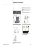
How to plug in the removable part
20 - 51226360F0 - REV. C0
Conditions:
b door closed
b earthing switch open
b the low voltage plug fixed to
the circuit breaker
b racking-in interlock unlocked
b circuit breaker open
Set the selector to the racking
position.
Insert the crank handle into hole.
Plug in the removable part by
turning the crank handle
clockwise until the position
indicator changes state.
Set the selector to the service
position.
In the case of a circuit breaker,
electrical operation is now
possible.
Schneider Electric
Conditions:
b removable part in plugged in
position.
200805
200804
200803
200634
How to draw out the removable
part
200802
Operating instructions (cont’d)
Schneider Electric
Remove all racking locks. Set
the selector to the racking
position
Insert the crank handle into hole.
Withdraw removable part by
turning the crank handle anticlockwise until the position
indicator changes state.
Set the selector to the service/
test position.
In the case of a circuit breaker,
electrical operation is now
possible.
51226360F0 - REV. C0 - 21
Operating instructions (cont’d)
On a basic cubicle
200654
How to close the earthing switch (yellow
background front plate)
200807
Initial state:
b the removable part in the isolated position or removed from the
cubicle
check that the voltage indication lamps are off
b the locks, if any, should be set to enable operation.
L1
L2
Set the selector "4" to
by
pulling it out and then turning it.
L3
I
200808
o
L1
L2
4
44
L3
I
5
4
o
Insert the crank handle into the
operation shaft "5" and turn the
handle clockwise until the
position indicator "L" changes
state. Closure is accompanied
by a distinctive sound.
200809
L
L1
L2
Set the selector "4" to I by
pulling it out and then turning it.
L3
I
4
200810
o
L1
L2
L3
I
22 - 51226360F0 - REV. C0
The earthing switch is now in the
earthed position. The MV cable
connections are now shortcircuit and earthed.
4
o
4
4
Schneider Electric
On a basic cubicle
How to open the earthing switch (yellow
background front plate)
200811
Initial state:
b the earthing switch is closed
b the locks, if any, should be set to enable operation.
L1
L2
Set the selector "4" to
by
pulling it out and then turning it.
L3
I
200812
L1
L2
4
44
o
L3
I
5
4
o
Insert the crank handle into the
operation shaft "5" and turn the
handle anti-clockwise until the
position indicator L changes
state. Closure is accompanied
by a distinctive sound.
L
200813
200660
Operating instructions (cont’d)
L1
L2
L3
I
o
Schneider Electric
4
Set the selector "4" to o by
pulling it out and then turning it.
The earthing switch is now in the
open position.
44
51226360F0 - REV. C0 - 23
Operating instructions (cont’d)
On a basic cubicle
200815
How to plug in the voltage transformer
(blue background front plate)
6
200816
Initial state:
b lower panel mounted
b selector "6" at
6
6
6
Set the selector "6" to
by pulling it out and then turning it.
200817
7
6
200818
Insert the crank handle into the operating shaft "7" and turn the
handle clockwise until the plugging in is complete. Plugging is
completed when resistance is felt.
6
66
Set the selector "6" to
24 - 51226360F0 - REV. C0
by pulling out and turning.
Schneider Electric
Operating instructions (cont’d)
On a basic cubicle
200819
How to drawout the voltage transformer
(blue background front plate)
6
200820
Initial state:
b lower panel mounted
b selector "6" at
6
66
Set the selector "6" to
by pulling it out and then turning it.
200821
7
6
6
6
200815
Insert the crank handle into the operating shaft "7" and turn the
handle anti-clockwise until the withdrawal is complete. Withdrawal
is completed when resistance is felt.
6
Set the selector "6" to
by pulling out and then turning it (this
allows the access panel to be removed).
Schneider Electric
51226360F0 - REV. C0 - 25
Operating instructions (cont’d)
Locking and prevention by 6
to 8 mm diameter padlocks
Number of padlocks on each cubicle
b 2 on the racking in prevention lever
b 3 on the earthswitch operation selector
b 3 on the VT racking in selector
b 3 on the bushing shutter mechanism.
200822
200669
To prevent plugging in of the removable part
L1
L2
L3
I
4
o
H
Pull out the lever H and fit the padlock in the oblong hole.
Preventing opening of the bushing shutters
Lock closed
On the bushing shutter mechanism when shutters are closed. The
bushing shutter mechanism is inside the cubicle on the right hand
side.
L1
L2
200826
200825
200665
Locking the earthing switch in the open or closed
position
L3
L1
L2
L3
I
4
o
Earthing switch open: fit 1 to 3
locks to the selector "4" to
prevent closing.
4
o
I
Earthing switch closed: fit 1 to 3
locks to the selector "4" to
prevent opening. This also
prevents racking in of the
withdrawable part.
200828
200827
Locking operation of the withdrawable VT
6
VT racked in: fit 1 to 3 padlocks
to the selector "6" to prevent
drawing out. This also prevents
removal of the front panel.
26 - 51226360F0 - REV. C0
6
VT racked out: fit 1 to 3 padlocks
to the selector "6" to prevent
plugging in of the VT.
Schneider Electric
Operating instructions (cont’d)
Interlocking by locks (option) b removable part in draw out position: 1 lock on the racking
mechanism front plate
b (2 O) or (2 C) or (1 O & 1 C): on the earthing switch
b disconnector truck (drawout busbar bridge)
b 1 lock in plugged in position (on earthing switch).
b removable part in drawn out position
b earthing switch.
Interlocking by
electromagnet (option)
Locking the removable part in the plugged in
position
b earthing switch closed
b busbar bridge plugged in.
The key is released only if the earthing switch is locked.
200829
200665
Interlocking the earthing
switch
L1
L2
L3
I
4
o
200830
200669
To prevent plugging in of the removable part.
L1
L2
L3
I
B
4
o
H
Pull out the level H and turn key lock at B and remove key.
Schneider Electric
51226360F0 - REV. C0 - 27
Preventive maintenance
Trouble shooting
Table for drawout circuit breaker and cradle
Symptoms
The circuit breaker on its truck was just
inserted into its cradle.
The selector is in the circuit breaker
extraction authorisation and removal
position:
The selector cannot be turned to the rack-in
authorised position.
The circuit breaker is racked-in
The truck selector is in the closing
authorised position.
The circuit breaker is CLOSED:
The selector cannot be turned to the rackout authorised position
The circuit breaker is racked-in
The truck selector is in the closing
authorised position.
The circuit breaker is OPEN:
The selector cannot be turned to the rackout authorised position.
The circuit breaker on its truck was just
racked-in.
b by using the handle (version using
propulsion)
Selector rotation to the closing authorised
position is not possible.
Faulty mechanisms
Probable causes and solutions
The low voltage plug and the upper front cover Check that the low voltage plug was
of the circuit breaker.
connected, the upper cover on the circuit
breaker is correctly closed.
The notching pins of the circuit breaker truck. Make sure that nothing blocks the notching
pins movement on the rails.
A lock on the cubicle's front door.
Make sure that any possible locks on the
cubicle's door do not act against the circuit
breaker's truck. Close the cubicle's door.
The selector and its padlocking function.
The truck selector is ready to receive a
padlock. Close the padlock hole.
The automatic opening function of the circuit Manually open the circuit breaker using the
breaker via the selector
opening pushbutton.
In the case of a cubicle that has a locked door:
electrically open the circuit breaker.
In both cases contact a Schneider Electric
service centre.
The safety function that prevents rack-in/out of One of the circuit breaker's pole has remained
the circuit breaker, if one of the circuit breaker closed despite the opening order on the circuit
poles remains closed.
breaker.
Contact a Schneider Electric service
centre.
The notching pins on the truck.
The truck notching pins are slightly blocked in
the notch holes in the rail.
Help disengage the crank notches using a
tool.
Check the correct operation by re-conducting
the manoeuvre.
The circuit breaker is not completely racked-in. b version with propulsion:
Re-insert the handle into the truck's rack-in
hole and continue to turn until rack-in has been
completed.
The propulsion handle
(if there is one).
The circuit breaker on its truck is in the test The propulsion handle
position after racking-out (selector in the
(if there is one).
rack-in authorised position):
The selector cannot be turned.
Selector rotation is impossible with the
propulsion handle inserted into the truck.
Withdraw the handle.
Selector rotation is impossible with the
propulsion handle inserted into the truck.
Withdraw the handle.
Truck with propulsion version:
Interlocking with the cubicle's earthing switch Open the earthing switch or free the lock to
The circuit breaker on its truck is in the test or locked to prevent rack-in stemming from the prevent rack-in on the cubicle.
position in the cubicle.
cubicle.
The selector can be turned to 3 positions:
The propulsion handle cannot be inserted
all the way into the truck to allow for the
circuit breaker to be racked-in.
28 - 51226360F0 - REV. C0
Schneider Electric
Preventive maintenance (cont’d)
Replacing the withdrawable VT fuses
200908
Initial position VT racked out.
Remove the lower front cover (4 screws).
200910
Replacing the withdrawable VT fuses
Removal
Remove the lower front panel.
200909
Installation
Unscrew the end caps on the VT.
Remove and replace the fuses (s).
Plug in the VT carriage.
200911
Replace the lower front panel.
Rack in the VT.
Schneider Electric
51226360F0 - REV. C0 - 29
30 - 51226360F0 - REV. C0
Schneider Electric
Schneider Electric
51226360F0 - REV. C0 - 31
32 - 51226360F0 - REV. C0
Schneider Electric
Schneider Electric Industries SAS
Address:
Department MV
F - 38050 Grenoble cedex 9
Tel : +33 (0)4 76 57 60 60
Fax : +33 (0)1 47 51 80 20
As standards, specifications and designs change from time to time, please ask for confirmation
of the information given in this publication.
This document has been printed on ecological paper.
http:/www.schneiderelectric.com
RCS: Nanterre B 954 503 439
Design: Technical documentation department Medium Voltage, Varces (38), France.
51226360F0 - REV. C0
10/2003
51226360F0 - REV- C0 © 2003 - Schneider Electric - All rights reserved.
The Schneider group service centres are at your service for:
engineering and technical assistance
commissioning
training
preventive and corrective maintenance
adaptation
spare parts.
Contact your sales representative who will put you in touch with your nearest
Schneider group service centre or call us on 33 (0)4 76 57 60 60
(Grenoble, France).


